

Abstract
Multileaf collimator (MLC) is among the radiation field shaping systems used for conformal radiotherapy and intensity modulation radiation therapy techniques. The MLC system that has been designed and fabricated in this study includes 52 leaves, 52 stepper motors, 2 DC motors, 16 programmable logic controllers (PLCs) and one human machine interface (HMI). This system can be mounted on conventional linear accelerators (linac) as an add-on accessory. The 52 leaves are mounted on two carriages that are moved independently. The leaves sequence acquired from the image processing of computed tomography images is used to arrange leaves. This sequence is saved in a text file. The leaves are arranged by HMI and labVIEW. Using HMI it is possible to test the operation of PLCs and manually enter the numerical values of the leaves edges. An executable file is developed by labVIEW program, which is graphically user interfaced between the operator and the MLC control system. The projected width of each leaf on the isocenter accelerator (usually at 100 cm from the source) is 10 mm. The positioning accuracy of each leaf is approximately 1.4 mm.
Keywords: Control, design, fabrication, multileaf collimator
INTRODUCTION
In the last few years the focus in the field of radiation therapy has been on how to improve tumor control by increasing total dose per fraction, while keeping the dose to organs at risk as low as possible.[1] Many organs such as the spinal cord, salivary glands, lungs and eyes are relatively sensitive to radiation damage therefore they must be given special consideration during radiotherapy treatment planning. Explicit field shaping of the beam is required to reduce the amount of healthy tissue irradiated, and multiple beams are used to lower the dose absorbed by tissue outside the target volume.[2]
It is achieved through high-precision and high-gradient dose irradiation techniques. Stereotactic treatment of brain metastases treated in a single session is the most significant example of this kind of approach. However, stereotactic radiation therapy is usually employed to treat lesions with a diameter smaller than 35 mm and an extremely simple shape.[3,4]
Among the shaping systems that are used to match the radiation field against the contour of target volume, can be mentioned to multileaf collimator (MLC). MLC has movable leaves, or shields, which can shield some fraction of the radiation beam; typical MLCs have 20-120 leaves, arranged in pairs. By using a computer control to position a large narrow, closely abutting leaves, an arbitrary shaped field can be generated.[2]
There are many researchers to design a computer-controlled MLC system[5,6,7] and the effects on patient dose.[8,9] Design and construction stages of our prototype MLC included the following sections: Mechanics,[10,11] image processing of CT slices[12] and control.[13] This article explains the control process of our MLC design and fabrication. The design of an alternative control section of MLC system that allows a high precision shaping of large fields is also presented in this article. In comparison with other MLC system that is controlled by the microcontroller,[14] this system is controlled precisely and easily by programmable logic controllers (PLCs) and can be improved in future studies.
MATERIALS AND METHODS
The MLC system consists of 52 leaves, 52 stepper motors,[15] 2 DC motors,[16] 16 PLCs[17] and one human machine interface (HMI).[17] Figure 1 schematically shows the flow diagrams used in MLC system designed.
Figure 1.
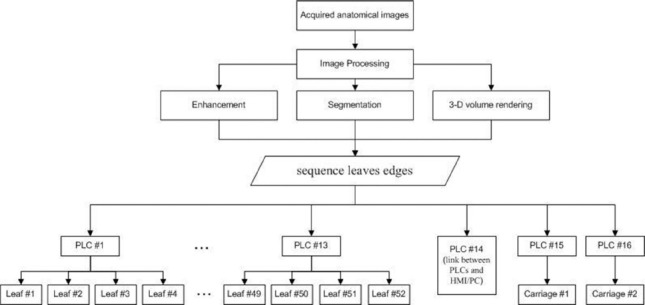
Schematic diagram of multileaf collimator system
The specifications and functions of this prototype MLC prototype be described as following:
Mechanical Part
In the research phase of this study, aluminum alloy was used for the construction of leaves as the material of choice because of its low machining cost. The collimating device is made up of two opposing banks of 26 pairs of leaves 5 cm in height, 20 cm in length and 1 cm in width. The projected width of each leaf and the maximum field size on the isocenter of a Varian linear accelerator can be 10 mm and 26 cm × 40 cm, respectively. The 52 leaves (26 per side) are mounted on two carriages that are moved independently, to extend their movements across the radiation field. The leaves ends move perpendicular to the beam's central axis and have parallel design.[12] The top view of the designed MLC is shown in Figure 2.
Figure 2.
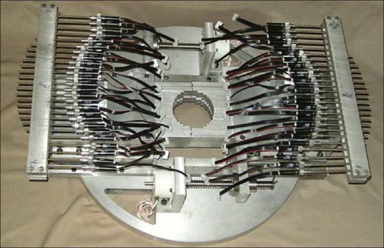
A top view of the multileaf collimator system
Dynamic Part
Each leaf is moved by a combination, including three parts: A DC motor, a gearhead and an encoder.[17] Triangular thread screws are used to convert rotation to linear motion. The pitch of the thread is 0.7 mm. Miniature slit-type flexible coupling is used between the DC motor shaft and the screw in each leaf.[16] This part is shown in Figure 3.
Figure 3.
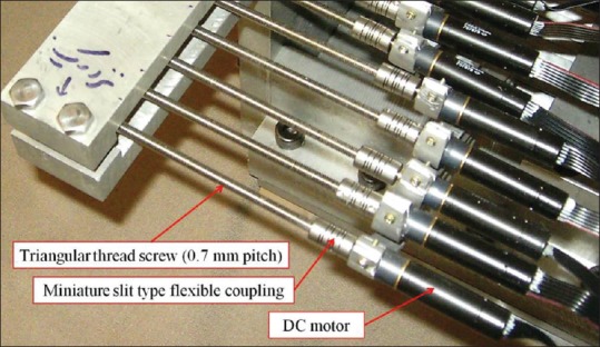
A view of the triangular thread screws, miniature slit type flexible couplings and the DC motors
This coupling is used to prevent nonaxial between the motor shaft and the triangular thread screw. This part is shown in Figure 4.
Figure 4.
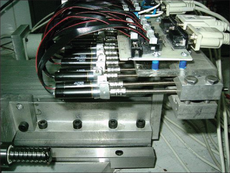
A view of the dynamical part of the multileaf collimator system
Control Part
The MLC control unit consists of 14 PLCs to control the motors and 2 PLCs to control the two carriages. One of the PLCs is the link between PLCs and HMI/PC. Each four contiguous leaves are controlled by one PLC. The connection through PLCs is done via the RS-485 port. The communication between the operator and the MLC system is done via two ways: HMI and PC. HMI and PC be communicating with one of the PLCs (mentioned above) by RS-485 port and RS-232 to RS-485 converters, respectively.[11] The two power supplies are provided 24 VDC. Changing the direction of leaf motion is done by the power relay.[11,17] This power relay is controlled by one of the PLCs. These elements (PLCs, power supplies, power relay, converter and HMI) are installed into a computer case, which is shown in Figure 5.
Figure 5.
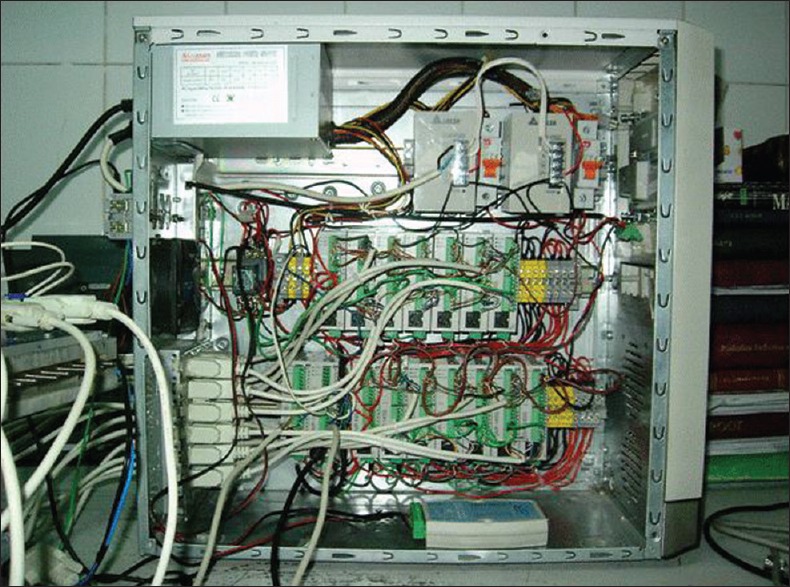
An inside view of the PC case
The feedback that is obtained from the revolution of the motor shaft is sent to the PC by the encoder and RS-232 port. The detection of the leaf position and the operation of the motor are done by this feedback.
The computer-controlled MLC system is done in the environment of labVIEW program. In this program, an executable file is developed under the name of MLC.vi. This program is graphical user interface between the operator and the MLC control unit.
Image Processing Part
The information acquired from a tomography technique such as a computed tomography (CT) machine is used to move the leaves of an MLC system. As a result, they form a specific shape, e.g. a tumor. The image forming is accomplished by utilizing some of the functions available in MATLAB. The functions are used to extract the geometrical data including as acquisition, enhancement, and segmentation of the images, three-dimensional image reconstruction, extracting sagittal and coronal images.
The position of leaves, which is called sequence leaves edges, can be saved in a text file. This file must include 52 numbers that are the coordinates of the contour of target volume.
RESULTS
The leaves are arranged by the following ways: (a) Using HMI it is possible to test the operation of PLCs and manually enter the numerical values of the leaves edges; (b) using labVIEW program an executable file is developed that is graphically user interfaced between the operator and the MLC control system. In this program, it is possible to load the file including sequence leaves edges and then view the leaf arrangements obtained through the encoder feedback of each motor. It is also possible to manually enter the numerical values of the leaves edges in two columns. The environment of this program and the MLC configuration are shown in Figures 6 and 7.
Figure 6.
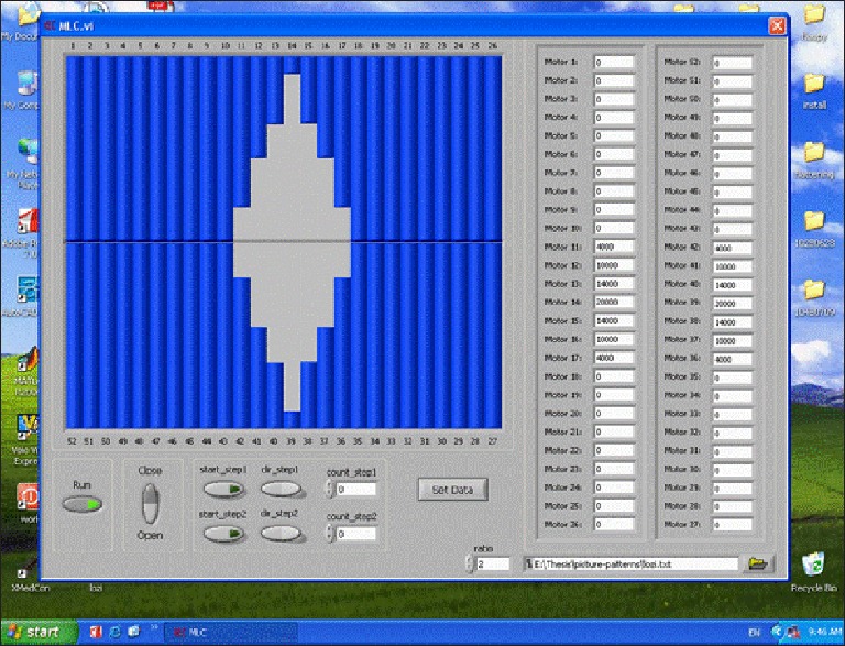
A view of multileaf collimator.vi program
Figure 7.
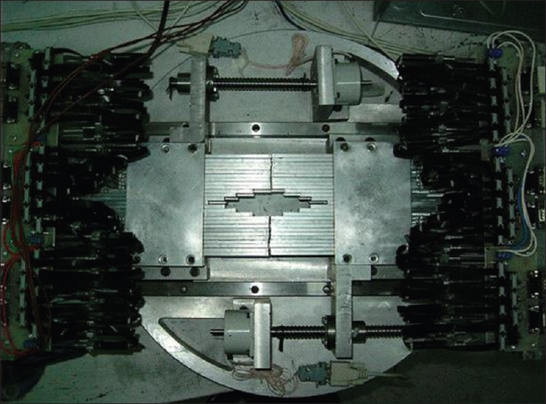
Multileaf collimator configuration
CONCLUSIONS
The projected width of each leaf on the isocenter accelerator (usually at 100 cm from the source) is 10 mm. The positioning accuracy of each leaf is approximately 1.4 mm.
Since the screws inherently have an axial backlash, they are not suitable choice for positioning. Therefore, it is suitable to use ball screws and roller cage.
In this MLC prototype, the control part is designed and fabricated by using the PLCs. The advantages of PLC with respect to the microprocessors are described as following:
The capability to easily develop the dynamical part such as in changing the geometrical design of the leaf
The capability to detect leaf position in achieving safe and reliable position control using the mechanism such as video-optical system, without making important changes in wiring.
The feedback received directly from the encoder is valuable, but in the view point of the positioning leaves is not reliable. Because if for any reason the transmission path of the DC motors of leaves it is disconnected (such as screws couplings relaxes and finally separated from the coupling DC motors and motor screws) feedback encoder was received. Actually leaves are fixed, and this event is very undesirable. Because the need is to install sensors to place directly from the leaves position status Information is more accurate.
If for any reason MLC leaves are fixed in place to the system, it is possible that the relevant residual DC motors work and will cause serious damage to the engine is entered. Hence, it is worthy, if the feedback from the motor encoder is not received; the system power supply automatically cut, and the user notify it.
In a typical MLC configuration, each leaf is moved to the opposing leaves or vice versa by using the power relay, simultaneously. It is a potential limitation to decrease the time for the MLC configuration. It is hoped that this limitation is removed in the future designs via to develop the control part.
BIOGRAPHIES

Abdolreza Hashemian Medical Physics Research Center, Medical Physics Department, Faculty of Medicine, Mashhad University of Medical Sciences, Mashhad, Iran Tel: 098 5138002328 Fax: 098 5138002320 Postal address: Department of Medical Physics, Faculty of Medicine, Mashhad University of Medical Sciences, Mashhad, Iran.
E-mail: hashemianr@yahoo.com

Mohammad Taghi Bahreyni Toossi Medical Physics Research Center, Medical Physics Department, Faculty of Medicine, Mashhad University of Medical Sciences, Mashhad, Iran Tel: 098 5138002316 Fax: 098 5138002320 Postal address: Department of Medical Physics, Faculty of Medicine, Mashhad University of Medical Sciences, Mashhad, Iran.
E-mail: Bahreynimt@mums.ac.ir

Shahrokh Nasseri Medical Physics Research Center, Medical Physics Department, Faculty of Medicine, Mashhad University of Medical Sciences, Mashhad, Iran Tel: 098 5138002328 Fax: 098 5138002320 Postal address: Department of Medical Physics, Faculty of Medicine, Mashhad University of Medical Sciences, Mashhad, Iran.
E-mail: naserish@mums.ac.ir; shahrokh.nasseri@gmail.com
ACKNOWLEDGMENTS
This research project was supported by a grant from Vice Chancellor for Research at Mashhad University of Medical Sciences, Mashhad, Iran.
Footnotes
Source of Support: Nil
Conflict of Interest: None declared
REFERENCES
- 1.Loi G, Pignoli E, Scorsetti M, Cerreta V, Somigliana A, Marchesini R, et al. Design and characterization of a dynamic multileaf collimator. Phys Med Biol. 1998;43:3149–55. doi: 10.1088/0031-9155/43/10/033. [DOI] [PubMed] [Google Scholar]
- 2.Boyer A. Committee ART. Madison: American Association of Physicists in Medicine; 2001. Basic Applications of Multileaf Collimators. [Google Scholar]
- 3.Bahreyni Toossi MT, Khoshbin Khoshnazar AR. Development of a prototype stereotactic collimation assembly for Neptun 10 PC linac. Iran J Radiat Res. 2004;2:135–40. [Google Scholar]
- 4.Khoshnazar AK, Toossi MB, Hashemiyan A, Toossi MB, Salek R. Quality assurance program for prototype stereotactic system developed for Neptun 10 PC linac. Iran J Radiat Res. 2005;3:73–8. [Google Scholar]
- 5.Jordan TJ, Williams PC. The design and performance characteristics of a multileaf collimator. Phys Med Biol. 1994;39:231–51. doi: 10.1088/0031-9155/39/2/002. [DOI] [PubMed] [Google Scholar]
- 6.Galvin JM, Smith AR, Moeller RD, Goodman RL, Powlis WD, Rubenstein J, et al. Evaluation of multileaf collimator design for a photon beam. Int J Radiat Oncol Biol Phys. 1992;23:789–801. doi: 10.1016/0360-3016(92)90652-x. [DOI] [PubMed] [Google Scholar]
- 7.Topolnjak R, van der Heide UA, Raaymakers BW, Kotte AN, Welleweerd J, Lagendijk JJ. A six-bank multi-leaf system for high precision shaping of large fields. Phys Med Biol. 2004;49:2645–56. doi: 10.1088/0031-9155/49/12/012. [DOI] [PubMed] [Google Scholar]
- 8.Jabbari K, Anvar HS, Tavakoli MB, Amouheidari A. Monte Carlo Simulation of Siemens ONCOR Linear Accelerator with BEAMnrc and DOSXYZnrc Code. J Med Signals Sens. 2013;3:172–9. [PMC free article] [PubMed] [Google Scholar]
- 9.Atarod M, Shokrani P. Monte Carlo Study of Fetal Dosimetry Parameters for 6 MV Photon Beam. J Med Signals Sens. 2013;3:31–6. [PMC free article] [PubMed] [Google Scholar]
- 10.Hashemiyan AR, Bahreyni Toossi MT, Nasseri SH. Design and fabrication of the mechanical part of a prototype multileaf collimator system. Presented at the International Conference on Medical Physics (ICMP 16th), Dubai. 2008 Apr 14-16; [Google Scholar]
- 11.Bahreyni Toossi MT, Hashemiyan AR, Nasseri SH. Design and fabrication of the mechanical part of a prototype multileaf collimator system. Iran J Med Phys. 2008;4:11–8. [Google Scholar]
- 12.Bahreyni Toossi MT, Hashemiyan AR, Nasseri SH. Three dimensional computed tomography reconstruction of leaf arrangement of a multileaf collimator. Presented at the International Conference on Medical Physics (ICMP 16th), Dubai. 2008 Apr 14-16; [Google Scholar]
- 13.Bahreyni Toossi MT, Hashmian A, Nasseri SH. International Federation for Medical and Biological Engineering. Poster Presentation, Munich, Germany; 2009. Sep 7-12, Design and fabrication of the control part of a prototype multileaf collimator system. [PMC free article] [PubMed] [Google Scholar]
- 14.Kamali-Asl A, Batooli A, Harriri S, Salman-Rezaee F, Shahmardan F, Yavari L. Design, simulation and manufacture of a multi leaf collimator to confirm the target volumes in intensity modulated radiation therapy. 2010. Iran J Med Phys. 2012;9:111–25. [Google Scholar]
- 15.Maxon Motor. [Last accessed on 2014 Jun 28]. Avaliable from: http://www.maxonmotor.co.uk/index.htm .
- 16.SDP/SI stock Drive Products/Sterling Instrument. [Last accessed on 2014 Jun 28]. Available from: http://www.sdp-si.com .
- 17.Delta Detta Electronics, INC; [Last accessed on 2014 Jun 28]. Available from: http://www.delta.com.tw/ [Google Scholar]