Abstract
Background
Intraoperative rupture (IOR) is a rare, but potentially morbid complication of endovascular aneurysm coil embolization. Yet, IOR predictors have remained relatively uninvestigated in relation to coil design.
Objective
To develop a novel in vitro aneurysm model to characterize forces exerted by coils of different design on the aneurysm during endovascular embolization that are hypothesized to contribute to IOR.
Methods
A 3 mm saccular aneurysm model was developed with flat latex membrane at the dome apex. Membrane deflection was observed throughout simulated embolization and converted to force measurement. Simultaneous coil insertion and force measurement were accomplished with a compression strength-testing machine (CSTM). Membrane and insertion forces across coil type, microcatheter tip placement, and insertion rate were evaluated.
Results
Insertion force and force directly on the aneurysm wall exhibited a difference, with framing coils exerting greatest force, followed by filling and finishing coils. Regarding microcatheter placement, a similar graded response in membrane and insertion forces was observed with positioning in the top-third of the aneurysm generating the greatest force compared to central and bottom-third placement. Insertion rate was also a factor with the slowest rate (10 mm/min) exhibiting the greatest membrane force, followed by lower forces at 30 and 50 mm/min. A multiple linear regression model was created to assess contributions of each factor towards aneurysm forces.
Conclusion
Increased force on the aneurysm is associated with framing coil use, microcatheter placement proximal to aneurysm dome, and slow insertion rate. Further characterization remains necessary to reduce IOR risk, especially concerning contributions of insertion rate.
Keywords: Coil embolization, Intracranial aneurysm, Intra-procedural rupture, Insertion force
Introduction
Despite improvements in catheters, coils, and balloons, complication rates of endovascular coil aneurysm occlusion remain significant. One important complication is intraoperative rupture (IOR). Although reports suggest low overall IOR risk, associated morbidity and mortality can be substantial and little is understood regarding biomechanical forces involved.1 IOR has been observed to occur as a consequence of aneurysm wall perforation by microcatheter, guide wire, or endovascular coil, in addition to increased intra-aneurysm pressure due to coil insertion and over packing.2,3 Compared to aneurysm clipping, IOR during coiling exhibits exaggerated adverse effects due to decreased ability to control bleeding, manage new subarachnoid hemorrhage, and prevent elevated intracranial pressures.1 Documented factors that increase IOR risk include small aneurysm size (≤ 3 mm diameter),4 previous rupture,5 and microcatheter tip placement against aneurysm wall.1
While coil manufacturers qualitatively describe implant stiffness, absolute forces exerted by coils during embolization have only recently been investigated.6 Numerous variables exist that could modulate forces7 during framing, filling, and finishing stages. Yet, characterization has revolved around insertion force, which although intuitive to surgeons, may not indicate force directly on the aneurysm. Using insertion force as a surrogate of direct aneurysm force,8 various coil types have been analyzed across simulated embolizations,6 resulting in proposal of mechanical coil insertion systems.9 However, studies have not quantitatively related these insertion forces to those directly on the aneurysm or investigated reliability of insertion force as a correlate of force on the aneurysm wall — a critical point, as aneurysm force, not insertion force, is ultimately responsible for IOR.
In an effort to quantify relationships between insertion and aneurysm force to better understand mechanical effects of coil embolization and, more importantly, characterize IOR relevant force properties of different coil types, a novel system was developed to characterize both insertion and direct forces in a model saccular aneurysm. Based on implant material properties and geometry, different coil types were hypothesized to exert distinct aneurysm forces during embolization.6 Microcatheter placement was also expected to affect aneurysm force, as coil release closer to the dome could facilitate greater force transfer with less dissipation. Moreover, insertion rate was hypothesized to be correlated with direct aneurysm force, as faster insertion could facilitate a constant kinetic friction state requiring less insertion force than static friction states observed during slower insertion. Greater understanding of these variables may influence clinical technique and reduce IOR risk.
Methods
Aneurysm Model
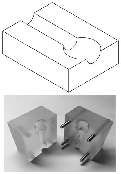
A 3 mm spherical aneurysm model with a 1.6 mm feeding artery was constructed of acrylic, in which the aneurysm dome was bisected to expose a 2.25 mm opening (Figure 1A). Latex membranes (0.150 mm) were affixed over exposed dome using double-sided adhesive tape (McMaster Carr, Elmhurst, IL). Force-displacement calibration of membranes on the model was obtained via a compression strength-testing machine (CSTM) (MTS 6 Sintech 20/G, MTS Systems Corporation, Eden Prairie, MN). Utilizing the latex membrane elastic modulus (1.1 MPa), which is of the same order of magnitude as aneurysm wall (2 MPa),10 finite element analyses (Abaqus, Dassault Systemes, Velizy-Villacoublay France) and classical theory of plates and shells predicted similar force-displacement relationships following simulated coil insertion (see Figure, Supplemental Digital Content 1). Latex was selected to increase displacement detection sensitivity.
Figure 1.
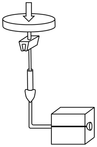
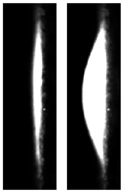
In vitro aneurysm model. (A) Model consisted of two acrylic blocks into which a 3 mm saccular aneurysm was patterned. Dome bisection created an opening over which a latex membrane was affixed. (B) A CSTM fed endovascular coils at a constant rate, while simultaneously measuring insertion force. (C) Latex membranes were visualized microscopically. Reference frames (left) were subtracted from frames captured during embolization (right). For each frame, maximum membrane displacement was calculated and converted to a force via calibration curve.
Membrane Force Measurement
Measurement of force exerted by inserted coil was obtained through membrane displacement detection. A microscope (Zeiss OPMI 1-FC, Carl Zeiss AG, Oberkocken, Germany) was focused along the model face at depth of the dome opening. Calibration of measured displacement was achieved through determination of length per pixel afforded by the microscope camera (AmScope MA1000-CK, AmScope, Irvine, CA) when imaging an object of known width. Force resolution was .355 mN.
Simulated Embolization
Simulated embolization was accomplished via automated insertion. A stage for the model, hemostatic valve Y-connector, and side camera was constructed to fix component positions. Membrane force was measured with microcatheter tip in the top-third (near dome), center, or bottom-third (near neck) of the aneurysm. Insertion occurred until implant length of a single coil was achieved.
Automated coil insertion was accomplished via CSTM (Figure 1B). A microcatheter was fixed proximally and insertion wire advanced by CSTM load cell. Telescoping hypodermic tubing prevented insertion wire bend during embolization. Three feed rates – 10, 30, and 50 mm/min – were implemented. In addition to controlling feed rate and measuring coil insertion length, the system facilitated insertion force measurement. Other than a bend from vertical insertion through CSTM to horizontal stage on which the model was fixed, the microcatheter was positioned linearly to prevent variable friction from a tortuous path.
Coil Types
Three coil types were utilized to compare insertion and resulting aneurysm forces. As a representative framing coil, the MicroVention Cosmos (MicroVention Inc., Tustin, CA, 3 mm diameter, 60 mm implant length) was implemented. Two filling coil types were represented by the MicroVention Versatile Range Fill Coil (VFC) (3-6 mm diameter, 60 mm length) and the MicroVention Hypersoft finishing coil (3 mm diameter, 60 mm length). Coil comparison was accomplished with central microcatheter placement and 30 mm/min insertion rate. Cosmos coil was utilized for analysis of effects of microcatheter placement and insertion rate.
Analysis
Image analysis was accomplished in MATLAB (Mathworks Inc., Natick, MA). For each video frame, maximum membrane displacement in comparison to reference images was measured (Figure 1C and Video, Supplemental Digital Content 2). Utilizing the calibration, maximum displacement was converted into maximum membrane force for each frame. Trials with microcatheter kickback or coil parent artery prolapse were discarded.
Statistical analyses were performed using SPSS (IBM, Armonk, NY) and MATLAB. ANCOVAs with coil length inserted as covariate were utilized to determine differences in insertion and membrane force across coil type, insertion rate, and microcatheter location. Kruskal-Wallis ANOVA was performed to determine effects of coil type, insertion rate, and microcatheter location on maximum insertion and aneurysm force across 10 mm insertion length segments. Post-hoc multiple comparisons tests utilized Bonferroni correction. Fieller's method was used to calculate 95% confidence intervals (CIs) for normalized insertion and membrane force ratios determined by estimated marginal means. Multiple linear regression was performed to model contributions of coil insertion length, insertion force, insertion rate, and microcatheter placement on aneurysm force during Cosmos coil embolization. Statistical significance was determined by P < .05.
Results
Simulated Embolization Force Measurement
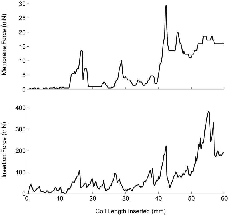
One hundred fifteen simulated embolizations were completed (Figure 2). Latex membranes were utilized for six consecutive trials before replacement as determined by calibration to ensure consistent membrane properties. Coil type, microcatheter placement, and insertion rate were randomized across membranes.
Figure 2.
Simulated embolization forces. Throughout simulated embolization with the Cosmos framing coil with central microcatheter placement and constant insertion rate of 30 mm/min, coincident membrane and insertion force peaks were observed as a consequence of microcatheter “painting” motion (see Videos, Supplemental Digital Content 2-3).
Effect of Coil Type
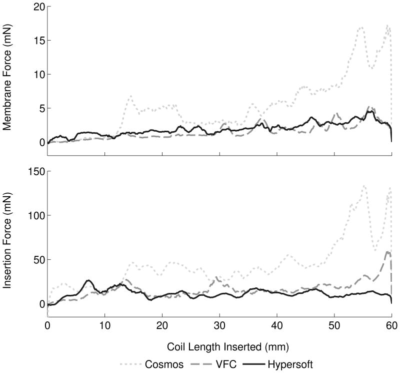
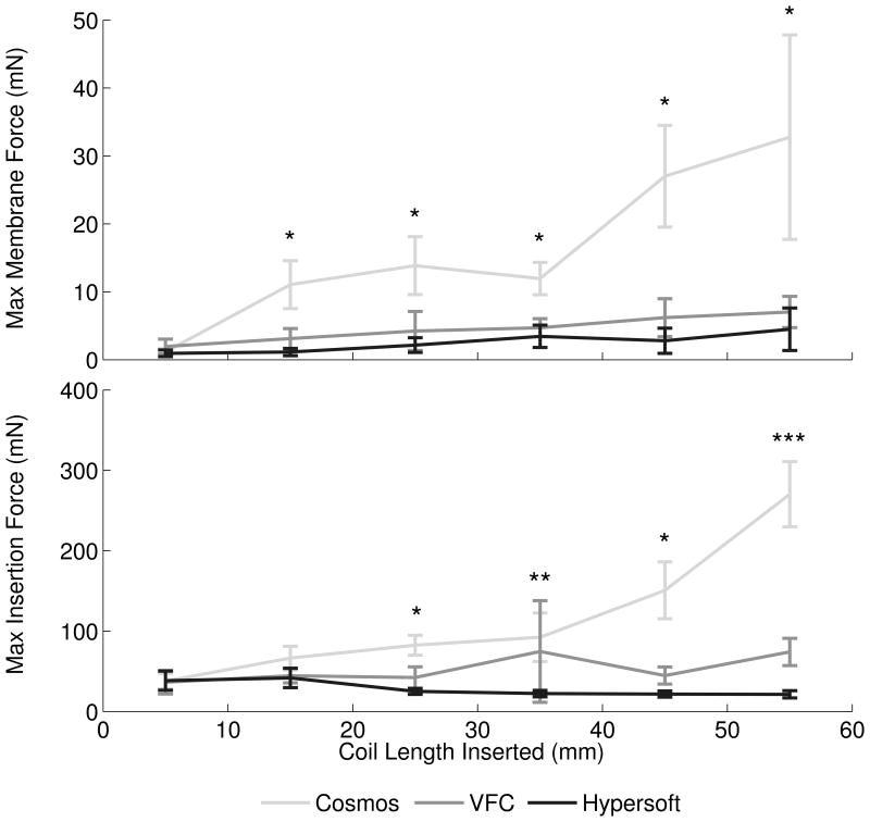
Analysis of coil type contribution to membrane and insertion forces was performed with central microcatheter placement and 30 mm/min insertion rate (Figure 3A). Embolizations with Cosmos (N = 13), VFC (N = 14), and Hypersoft (N = 14) coils were analyzed. ANCOVA indicated significant effect of Cosmos > VFC > Hypersoft on membrane force (P < .001). Membrane force ratio was 7.94: 1.72: 1 (Cosmos: VFC: Hypersoft). Regarding insertion force, ANCOVA similarly indicated Cosmos > VFC > Hypersoft (P < .001) with a ratio of 5.47:2.35:1. Comparisons of force ratios indicated non-overlapping insertion and membrane force CIs for Cosmos data when normalized to Hypersoft data (Figure 4A). Further analysis of coil type effects was performed by assessment of maximum aneurysm and insertion forces, which are theorized to be the most likely contributors to IOR (Figure 5A). Kruskal-Wallis ANOVA indicated Cosmos > VFC = Hypersoft on membrane force for all segments following the initial 10 mm of coil inserted (P < .001). Similar effects were observed in insertion force measurements following 20 mm of inserted coil (P < .001).
Figure 3.
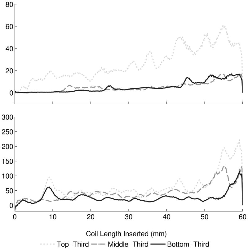
Mean membrane and insertion forces. (A) ANCOVA of forces across coil type indicated a significant effect of Cosmos > VFC > Hypersoft for membrane and insertion force (P < .001). (B) Analysis of microcatheter tip placement indicated a significant effect of Top > Middle > Bottom (P < .001) for membrane and insertion forces. (C) Insertion rate exhibited a significant effect of 10 mm/min > 30 mm/min > 50 mm/min in membrane force (P < .001). Effect on insertion force was 10 mm/min = 30 mm/min > 50 mm/min (P < .001).
Figure 4.
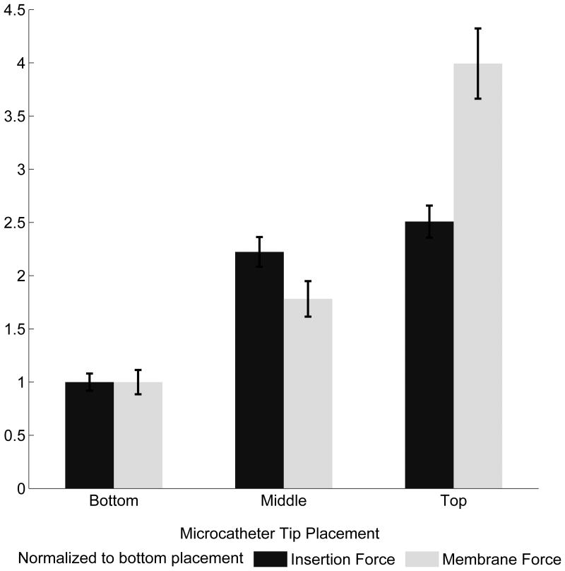
Membrane and insertion force characterization. (A) The Cosmos coil exerted approximately eight times the force of the Hypersoft coil on the aneurysm and required five times the insertion force. The VFC required approximately double the insertion force of the Hypersoft and imparted double the force of the Hypersoft onto the aneurysm. (B) Microcatheter tip placement facilitated greater insertion and membrane forces in positions near the dome and decreased with placement further from the dome. Although membrane forces doubled with each placement closer to the dome, this was not reflected in insertion force. (C) Insertion rate analysis indicated a trend of increasing insertion rate leading to decreased force on the aneurysm. However, this trend was not exhibited by insertion force.
Figure 5.
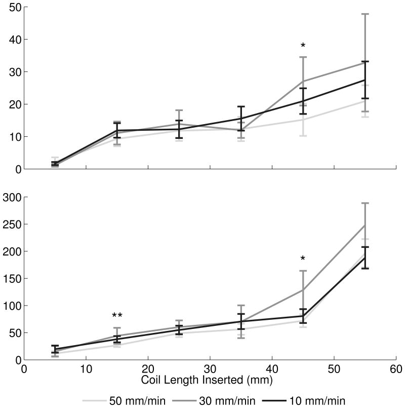
Maximum membrane and insertion forces. (A) Maximum aneurysm forces were greatest with the Cosmos coil, while maximum forces between VFC and Hypersoft filling coils were statistically indistinguishable. A similar effect was observed in insertion force data. [* Cosmos > VFC = Hypersoft, ** Cosmos > Hypersoft, *** Cosmos > VFC > Hypersoft] (B) Microcatheter placement exerted a graded effect of increasing force with placement more proximal to the dome. However, this relationship was not conserved in insertion force where placement in the top-third and center of the aneurysm were statistically indistinguishable, but both greater than placement in the bottom-third portion. [* Top = Middle > Bottom, ** Top > Middle > Bottom, *** Top > Bottom] (C) Insertion rate did not exhibit consistent effects on maximum observed membrane and insertion forces. For the majority of segments, insertion at all rates was statistically indistinguishable. [* 30 mm/min > 50 mm/min, ** 30 mm/min = 10 mm/min > 50 mm/min].
Effect of Microcatheter Tip Placement
Microcatheter placement contribution to aneurysm and insertion forces was analyzed through simulated embolizations with the Cosmos coil and 30 mm/min insertion rate (Figure 3B). Microcatheter tip placement varied from top-third (N = 19), middle-third (N = 13), and bottom-third (N = 15) of the aneurysm. ANCOVA revealed significant effect of top > middle > bottom on membrane force (P < .001) with a ratio of 3.99: 1.78: 1 (top: middle: bottom). Insertion force ANCOVA indicated a similar significant effect of top > middle > bottom (P < .001) with a ratio of 2.51: 2.22: 1. Analysis of force ratios indicated non-overlapping insertion and membrane force CIs for top-third and bottom-third microcatheter placement when normalized to placement in the aneurysm bottom-third (Figure 4B). Analysis of maximum membrane force through Kruskall-Wallis ANOVA indicated an effect of top > middle > bottom on membrane force for a majority of segments, including the initial 10 mm insertion region (P < .001) (Figure 5B). Regarding insertion force, a similar effect was observed in the initial 10 mm of coil insertion; however, for the remainder of insertion, an effect of top = middle > bottom was observed (P < .001).
Effect of Insertion Rate
Analysis of the effect of insertion rate on aneurysm and insertion forces was performed with the Cosmos coil and fixed microcatheter placement in the aneurysm center (Figure 3C). Coil insertion occurred at constant rates of 10 mm/min (N = 20), 30 mm/min (N = 13), and 50 mm/min (N = 20). ANCOVA indicated significant effect of 10 > 30 > 50 mm/min on membrane force (P < .001) with force ratios of 1.29: 1.24: 1 (10: 30: 50 mm/min). Regarding insertion force, ANCOVA revealed a significant effect of 10 = 30 > 50 mm/min (P < .001) with a ratio of 1.31: 1.35: 1. Comparison of force ratios indicated completely overlapping insertion and membrane force CIs for both 10 and 30 mm/min insertion rates normalized to insertion at 50 mm/min (Figure 4C). Kruskal-Wallis ANOVA performed on maximum membrane force indicated no significant differences between insertion speeds (each segment P > .05) across all segments except between 40-50 mm where an effect of 30 > 50 = 10 mm/min on membrane force was observed (P = .023) (Figure 5C). Similarly, insertion force displayed no significant differences across insertion rates at a majority of segments (each segment P > .05), except between 10-20 mm where an effect of 10 = 30 > 50 mm/min was observed (P = .013) and between 40-50 mm/min where 30 > 50 mm/min was observed (P = .010).
Endovascular Embolization Force Model
Multiple linear regression was performed on Cosmos data to generate a model encompassing contributions of inserted coil length, insertion force, insertion rate, and microcatheter placement on aneurysm force. All factors possessed a significant β-coefficient (P < .001) and R2 = .684 (Table 1).
Table 1. Aneurysm force model for Cosmos framing coil.
Multiple linear regression of Cosmos data revealed predictors of direct aneurysm force throughout embolization. Length of coil inserted and insertion force were positive predictors of membrane force, whereas insertion rate was a negative predictor. Microcatheter placement in the aneurysm top-third increased the basal force level, while placement in the aneurysm bottom-third decreased the basal force level, relative to placement in the aneurysm center.
| Membrane Force Predictors | β (95% CI) |
|---|---|
| Independent Variables | |
| Coil Length Inserted (mm) | 0.266 (0.261, 0.270) |
| Insertion Force (mN) | 0.074 (0.071, 0.076) |
| Insertion Rate (mm/min) | -0.042 (-0.048, -0.036) |
| Categorical Variables | |
| Top Placement | 6.754 (6.482, 7.025) |
| Center Placement | 0 |
| Bottom Placement | -4.027 (-4.313, -3.741) |
Discussion
Although IOR during endovascular coil embolization possesses an incidence of only 2-5%, it can result in quadrupled risk of morbidity and mortality.1 IOR has been observed due to coil over packing, increased coil insertion pressure, and aneurysm wall perforation by microcatheter, guide wire, or coil.2,3 Although insertion forces have been analyzed, they have not been related to forces directly on the aneurysm hypothesized to contribute to IOR.6,8,9 This study presents a novel in vitro 3 mm diameter spherical aneurysm model representing a high rupture scenario for determination of forces on a saccular aneurysm dome during simulated coil embolization for comparison to insertion force.
Simulated Embolization and Force Measurement
Maximum membrane deflections were observed during moments leading to microcatheter “painting” due to force build-up and subsequent relaxation (see Videos, Supplemental Digital Content 3-4). For each coil, consistent force peak quantities related to tertiary coil properties. Thus, as force peaks occur immediately before and during “painting”, the motion may indicate a procedural moment with increased IOR risk.
Coil Selection
Proper coil selection is vital for successful aneurysm obliteration while avoiding over packing or recurrence. Analysis of Cosmos framing coils, VFCs, and Hypersoft finishing coils indicated an expected force hierarchy with framing coils exerting greater forces than versatile range filling and helical finishing coils. Mean insertion and membrane forces indicated similar effects; however, analysis of ratios of membrane and insertion forces suggested that insertion force was not a reliable predictor of membrane force. Normalizing to Hypersoft embolization forces, the VFC exhibited a two-fold increase in membrane force, while the Cosmos displayed an eight-fold increase. Yet, this was not faithfully represented by Cosmos insertion force feedback, as only a five-fold difference was recorded, indicating force feedback as a general reference at best of aneurysm force.
Regarding maximum forces, a consistent effect of Cosmos > VFC = Hypersoft was observed in membrane and insertion force, similar to results observed when analyzing mean forces. Together, these results indicate increased risk of framing coil insertion compared to filling and finishing coils. Previous research9 has reported the incidence of lead coil complications, especially in aneurysms ≤ 10 mm in diameter. Current results indicate increased forces generated by framing coils may contribute to these complications. Although several studies have characterized insertion forces as correlates of forces contributing to rupture,6,8,9 the current findings indicate that they should be interpreted cautiously, as they may not reliably indicate aneurysm forces which appear more complex than simple correlations would predict. Factors hypothesized to contribute to this observation include variable friction between coil and microcatheter, geometrical and material coil properties, and microcatheter tortuosity. Thus, although insertion force serves as a general predictor, it may underestimate forces directly on the aneurysm and fail to scale in an intuitively appreciable manner.
Microcatheter Placement
While microcatheter perforation2,3 and kickback11 have been associated with complications and unsuccessful obliteration, the difference in aneurysm force by coil delivery in different positions has remained uninvestigated. Microcatheter tip placement in top-third, center, and bottom-third of the aneurysm during simulated embolization resulted in membrane and insertion force gradients with placement near the dome generating the greatest forces and placement near the neck generating the lowest forces. As with coil comparisons, insertion force was indicated only as a general predictor of membrane force. While membrane force exhibited a two-fold increase for every position closer to the dome, this was not reflected in insertion force, which scaled in an underestimating manner.
This observation was reflected in analysis of maximum insertion and membrane forces. Top placement was consistently greater than middle and bottom placement regarding membrane force. However, top and middle placements were indistinguishable regarding maximum insertion force. Thus, while microcatheter placement may be dictated by aneurysm specifics and kickback prevention11, the findings quantitatively confirm the intuition that placing the microcatheter tip closer to the aneurysm dome results in elevated aneurysm forces. Furthermore, top placement appeared to predispose greater microcatheter “painting” motions and resulted in more drastic movement compared to middle or bottom placement. As microcatheter movement within the aneurysm can contribute to IOR through wall perforation, the relationship between placement and microcatheter action may be an important consideration for IOR prevention.
Coil Insertion Rate
Clinically, insertion occurs in a “feed-pause-feed” manner as a result of manual insertion. Furthermore, rates are typically slow except in the case of IOR when rapid embolization is required,12,13 yet insertion rate has not been evaluated for its effect on the aneurysm or insertion force. Comparing insertion at 10, 30, and 50 mm/min, a significant difference in membrane force was observed with the slowest insertion generating greater force than the fastest. Similar results were found in insertion force with the slowest and median insertion forces generating equivalent forces, both greater than forces observed during rapid embolization.
Analysis of maximum membrane and insertion forces across varying insertion rates found no significant differences. These results indicate that insertion rate exerts minimal effect on insertion and membrane force. Moreover, faster insertion rates may lower forces exerted on the aneurysm. Similar results have been previously reported,14 indicating that constant kinetic friction states (requiring less force to overcome than static friction) account for reduced forces with rapid insertion, whereas static friction states occurring in slower insertions drive increased forces. While static friction states will inherently occur during manual insertion, minimizing these states can potentially reduce force imparted on the aneurysm by approximately 30%. However, interpretation may be restricted to conditions prescribed by the model as discussed in “Limitations”.
Multiple Linear Regression Model
Incorporating insertion rate and microcatheter placement data, a model for simulated embolization with the Cosmos coil was constructed to reveal contributions of insertion length, insertion force, insertion rate, and microcatheter placement to aneurysm force. Coil length inserted was a strong predictor of membrane force as a function of decreasing volume within the aneurysm, consistent with previous suggestions of an ideal lead coil length to avoid complications during initial coil placement.15 Insertion force was a positive, but weaker predictor of aneurysm force, suggesting a general relationship between insertion and membrane force. Meanwhile, insertion rate exhibited a negative correlation with membrane force due to differences in static and kinetic friction states. Varying placement of microcatheter tip resulted in baseline elevation (top-third) or decrease (bottom-third) in predicted membrane force relative to central placement.
Limitations
Compared to the clinical scenario, non-spherical aneurysms or forces to regions other than the dome were not examined, nor were more frequently coiled larger aneurysms. While the results suggest insertion forces as weak IOR predictors, the model does not account for multiple coils, tortuous vasculature, calcification, or balloons and stents – although these factors arguably increase insertion force, further reducing correlations with aneurysm force. The constant catheter insertion rate utilized is unlike manual insertion characterized by push-pull motions and intermittent advancement. Moreover, coil interactions with pulsatile blood flow and pressure or differences in friction between model components and in vivo vascular intima with reduced coefficient of friction16 remain unaccounted for in the model. Thus, the significance of insertion rate on force in vivo may be diminished, although this warrants further investigation, especially as increased insertion rates may be inadvertently accomplished with increased insertion forces clinically. Since aneurysm rupture thresholds remain poorly described, coiling force contributions remain difficult to place into clinical perspective.
Conclusion
Investigation of coil selection, microcatheter placement, and insertion rate resulted in quantitative evaluation of endovascular coiling with indications for increased IOR risk. Framing coil use, microcatheter placement proximal to dome, and slow insertion rate displayed associations with elevated aneurysm force. While these findings shed light on coil selection, technical factors related to IOR, and non-linear relationships between insertion and direct aneurysm force, continued characterization remains necessary to reduce IOR risk and associated morbidity and mortality, especially regarding the role of insertion rate.
Supplementary Material
Supplemental Digital Content 1: Figure. Latex Membrane and Aneurysm Wall Simulations. Finite element analyses (Abaqus, Dassault Systemes, Velizy-Villacoublay France) and classical theory of plates and shells calculations demonstrate similar force-displacement relationships after simulated coil insertion. Latex membranes and aneurysm walls were modeled as 2.25 mm circular plates with a thickness of .15 mm. Latex membranes were modeled with an elastic modulus of 1.1 MPa, whereas aneurysm walls were modeled with an elastic modulus of 2 MPa.10 The endovascular coil was modeled as a cylinder of .3 mm diameter with an elastic modulus estimated based on previously outlined calculations.7 As computed by finite element analyses, the force-displacement relationship of latex was .0071 mm/mN compared to .0033 mm/mN for aneurysm wall. Similarly, theory of plates and shells calculations demonstrated force displacement relationships of .0069 mm/mN and .0038 mm/mN for latex and aneurysm wall, respectively.
Supplemental Digital Content 2: Video. Membrane Displacement. A representative video of membrane displacement during a simulated embolization by Cosmos coil at 30 mm/min and central microcatheter tip placement demonstrates the raw images analyzed in the study.
Supplemental Digital Content 3: Video. Embolization: Manual Insertion. Simulated embolization was performed manually with the Cosmos coil under surgical microscope to demonstrate the interaction between the endovascular coil and the membrane. Specifically evident in the video is the relationship between insertion and increasing membrane displacement.
Supplemental Digital Content 4: Video. Embolization: Automated Insertion. Simulated embolization was performed with automated insertion by CSTM at a rate of 30 mm/min with the Cosmos coil and microcatheter tip placement in the center of the aneurysm. The painting motion of the microcatheter is evident and coincident with force build-up and release on the membrane.
Acknowledgments
We thank Mark Seniw for compression strength-testing machine assistance and Scott Simpson for model fabrication guidance.
Disclosure of Funding: Support provided by the National Institute of Biomedical Imaging and Bioengineering Grant 1R25EB013060. Work made use of central facilities supported by NSF DMR-0520513 at Northwestern University MRSEC. Coils provided by Mr John Heffernan of Microvention Inc.
Footnotes
Disclosure: The authors have no personal, financial, or institutional interest in any of the drugs, materials, or devices described in this article.
References
- 1.Elijovich L, Higashida RT, Lawton MT, Duckwiler G, Giannotta S, Johnston SC. Predictors and outcomes of intraprocedural rupture in patients treated for ruptured intracranial aneurysms: The CARAT study. Stroke. 2008;39:1501–1506. doi: 10.1161/STROKEAHA.107.504670. [DOI] [PubMed] [Google Scholar]
- 2.Li MH, Gao BL, Fang C, et al. Prevention and management of intraprocedural rupture of intracranial aneurysm with detachable coils during embolization. Neuroradiology. 2006;48:907–915. doi: 10.1007/s00234-006-0147-3. [DOI] [PubMed] [Google Scholar]
- 3.Tummala RP, Chu RM, Madison MT, Myers M, Tubman D, Nussbaum ES. Outcomes after aneurysm rupture during endovascular coil embolization. Neurosurgery. 2001;49:1059–1067. doi: 10.1097/00006123-200111000-00007. [DOI] [PubMed] [Google Scholar]
- 4.Hwang JH, Roh HG, Chun YI, et al. Endovascular coil embolization of very small intracranial aneurysms. Neuroradiology. 2011;53:349–357. doi: 10.1007/s00234-010-0735-0. [DOI] [PubMed] [Google Scholar]
- 5.Cloft HJ, Kallmes DF. Cerebral aneurysm perforations complicating therapy with Guglieme detachable coils: A meta-analysis. AJNR. 2002;23:1706–1709. [PMC free article] [PubMed] [Google Scholar]
- 6.Matsubara N, Miyachi S, Nagano Y, et al. Evaluation of the characteristics of various types of coils for the embolization of intracranial aneurysms. Neuroradiology. 2011;53:169–175. doi: 10.1007/s00234-010-0722-5. [DOI] [PubMed] [Google Scholar]
- 7.White JB, Ken CG, Cloft HJ, Kallmes DF. Coils in a nutshell: A review of coil physical properties. AJNR. 2008;29:1242–1246. doi: 10.3174/ajnr.A1067. [DOI] [PMC free article] [PubMed] [Google Scholar]
- 8.Matsubara N, Miyachi S, Nagano Y, et al. A novel pressure sensor with an optical system for coil embolization of intracranial aneurysms. J Neurosurg. 2009;111:41–47. doi: 10.3171/2009.1.JNS081181. [DOI] [PubMed] [Google Scholar]
- 9.Haraguchi K, Miyachi S, Matsubara N, et al. A mechanical coil insertion system for endovascular coil embolization of intracranial aneurysms. Neuroradiology. 2013;19:159–166. doi: 10.1177/159101991301900203. [DOI] [PMC free article] [PubMed] [Google Scholar]
- 10.Austin GM, Schievink W, Williams R. Controlled pressure-volume factors in the enlargement of intracranial aneurysms. Neurosurgery. 1989;24:722–730. doi: 10.1227/00006123-198905000-00011. [DOI] [PubMed] [Google Scholar]
- 11.Miyachi S, Izumi T, Matsubara N, Naito T, Haraguchi K, Wakabayashi T. The mechanism of catheter kickback in the final stage of coil embolization for aneurysms: The straightening phenomenon. Neuroradiology. 2010;16:353–360. doi: 10.1177/159101991001600401. [DOI] [PMC free article] [PubMed] [Google Scholar]
- 12.Kwon BJ, Han MH, Oh CW, Kim KH, Chang KH. Procedure-related hemorrhage in embolism of intracranial aneurysms with Gugliemi detachable coils. Neuroradiology. 2003;45:562–569. doi: 10.1007/s00234-003-1028-7. [DOI] [PubMed] [Google Scholar]
- 13.Brisman JL, Niimi Y, Song JK, Berenstein A. Aneurysmal rupture during coiling: Low incidence and good outcomes at a single large volume center. Neurosurgery. 2005;57:1103–1109. doi: 10.1227/01.neu.0000185631.20246.1a. [DOI] [PubMed] [Google Scholar]
- 14.Matsubara N, Miyachi S, Nagano Y, et al. Experimental study of generation pattern of coil insertion force using a force sensor system: Investigation of friction state between coil and aneurysm wall determined by difference of coil insertion method and insertion speed. J Neuro Endovasc Ther. 2010;4:84–90. Japanese Article. [Google Scholar]
- 15.Khatri R, Chaudhry SA, Suri MF, Cordina SM, Qureshi AI. Frequency and factors associated with unsuccessful lead (first) coil placement in patients undergoing coil embolization of intracranial aneurysms. Neurosurgery. 2013;77:452–458. doi: 10.1227/NEU.0b013e3182804ad1. [DOI] [PubMed] [Google Scholar]
- 16.Dunn AC, Zaveri TD, Keselowsky BG, Sawyer WG. Macroscopic friction coefficient measurements on living endothelial cells. Tribol Lett. 2007;27:233–238. [Google Scholar]
Associated Data
This section collects any data citations, data availability statements, or supplementary materials included in this article.
Supplementary Materials
Supplemental Digital Content 1: Figure. Latex Membrane and Aneurysm Wall Simulations. Finite element analyses (Abaqus, Dassault Systemes, Velizy-Villacoublay France) and classical theory of plates and shells calculations demonstrate similar force-displacement relationships after simulated coil insertion. Latex membranes and aneurysm walls were modeled as 2.25 mm circular plates with a thickness of .15 mm. Latex membranes were modeled with an elastic modulus of 1.1 MPa, whereas aneurysm walls were modeled with an elastic modulus of 2 MPa.10 The endovascular coil was modeled as a cylinder of .3 mm diameter with an elastic modulus estimated based on previously outlined calculations.7 As computed by finite element analyses, the force-displacement relationship of latex was .0071 mm/mN compared to .0033 mm/mN for aneurysm wall. Similarly, theory of plates and shells calculations demonstrated force displacement relationships of .0069 mm/mN and .0038 mm/mN for latex and aneurysm wall, respectively.
Supplemental Digital Content 2: Video. Membrane Displacement. A representative video of membrane displacement during a simulated embolization by Cosmos coil at 30 mm/min and central microcatheter tip placement demonstrates the raw images analyzed in the study.
Supplemental Digital Content 3: Video. Embolization: Manual Insertion. Simulated embolization was performed manually with the Cosmos coil under surgical microscope to demonstrate the interaction between the endovascular coil and the membrane. Specifically evident in the video is the relationship between insertion and increasing membrane displacement.
Supplemental Digital Content 4: Video. Embolization: Automated Insertion. Simulated embolization was performed with automated insertion by CSTM at a rate of 30 mm/min with the Cosmos coil and microcatheter tip placement in the center of the aneurysm. The painting motion of the microcatheter is evident and coincident with force build-up and release on the membrane.


