Abstract
Coronary artery bypass grafting (CABG) is one of the most commonly performed major surgeries in the United States. Autologous vessels such as the saphenous vein are the current gold standard for treatment; however, synthetic vascular prostheses made of expanded poly(tetrafluoroethylene) (ePTFE) or poly(ethylene terephthalate) (PET) are used when autologous vessels are unavailable. These synthetic grafts have a high failure rate in small diameter (<4 mm) applications due to rapid re-occlusion via intimal hyperplasia. Current strategies to improve clinical performance are focused on preventing intimal hyperplasia by fabricating grafts with compliance and burst pressure similar to native vessels. To this end, we have developed an electrospun vascular graft from segmented polyurethanes with tunable properties by altering material chemistry and graft microarchitecture. Relationships between polyurethane tensile properties and biomechanical properties were elucidated to select polymers with desirable properties. Graft thickness, fiber tortuosity, and fiber fusions were modulated to provide additional tools for controlling graft properties. Using a combination of these strategies, a vascular graft with compliance and burst pressure exceeding the saphenous vein autograft was fabricated (compliance = 6.0 ± 0.6 %/mmHg × 10−4, burst pressure = 2260 ± 160 mmHg). This graft is hypothesized to reduce intimal hyperplasia associated with low compliance in synthetic grafts and improve long term clinical success. Additionally, the fundamental relationships between electrospun mesh microarchitecture and mechanical properties identified in this work can be utilized in various biomedical applications.
Keywords: Electrospinning, vascular graft, compliance matching, microarchitecture, polyurethane, burst pressure, microphase separation
1. Introduction
Coronary artery bypass grafting (CABG) is one of the most commonly performed major surgeries in the United States with over 400,000 procedures performed annually at a cost of over $25 billion.1 Autologous vessels such as the saphenous vein or mammary artery are the gold standard for treatment; however, autologous grafts are unavailable in up to 20% of patients due to disease, trauma, or anatomic abnormalities.2 Synthetic vascular prostheses made of expanded poly(tetrafluoroethylene) (ePTFE) or poly(ethylene terephthalate) (PET) are a common alternative to autologous vessels. These grafts are poor options in small diameter (<4 mm) applications due to high failure rates as a result of rapid re-occlusion. Synthetic grafts have a 40–50% reduction in patency after two years and 40% of grafts completely fail within 5 years.3, 4 This re-occlusion has been attributed to the occurrence of intimal hyperplasia at the distal anastomosis.3, 5 Intimal hyperplasia is characterized by smooth muscle cell migration from the medial layer of the vessel to the intimal layer followed by proliferation, resulting in narrowed artery diameter. Current strategies are focused on inhibiting intimal hyperplasia to improve the long-term clinical success of synthetic, small-diameter vascular grafts.
Recent studies have reported a strong correlation between graft mechanical properties and intimal hyperplasia onset and severity. Compliance, a measurement of graft change in diameter over a given pressure range, has been identified as a key determinant of graft success. Improved compliance between the vessel and the synthetic graft has the potential to reduce intimal hyperplasia and improve graft success. Despite having high burst pressure and suture retention strengths, PET and ePTFE compliance values are much lower than native vessel values.3 As a result, the compliant artery will expand and contract to maintain constant wall shear stress within the vessel, whereas the stiff synthetic graft resists the corresponding change in diameter. This compliance mismatch disrupts blood flow and results in zones of recirculation, flow separation, and low wall shear stress at the endothelium.6 Low wall shear stress initiates the release of vasoactive substances, gene activation, protein expression, and cytoskeletal rearrangement that stimulate intimal hyperplasia.3 Therefore, a graft that more closely matches native arterial compliance can improve the long-term clinical success of synthetic vascular grafts by preventing flow disruption and the stimuli for intimal hyperplasia.
Native vessels consist of alternating layers of elastin and collagen which provide the vessel with both high burst pressure and high compliance (saphenous vein burst pressure: 1680 ± 307 mmHg7 and compliance: 4.4 ± 0.8 %/mmHg × 10−4 3). Reproducing these features in synthetic grafts continues to be challenging given that compliance and burst pressure are often inversely related in synthetic grafts. The hierarchical structure of alternating elastin and collagen in arteries provides tensile properties characterized by a low modulus with high elastic recovery followed by a strong strain hardening response at higher strains. A material that more closely mimics the stress response curve of native arteries has greater potential to match mechanical properties and reduce intimal hyperplasia. Segmented polyurethanes (SPUs) are a promising material due to their a high elasticity and a strong strain hardening response.8, 9 Vascular grafts fabricated from SPUs have been previously investigated, but these grafts were still unable to match the biomechanical properties of native vessels. Grafts such as the Corvita®, Thoratec®, and PulseTec® have been developed with modest improvements in compliance but were still lacking compared to autologous standards.10 Newer commercial SPU grafts such as the UCL-Nano™ and Myolink™ grafts, now available in Europe, have exhibited improved compliance values much greater than traditional synthetic grafts; however, these grafts have no recorded burst pressure exceeding autologous vessels.11, 12 Due to the highly tunable segmented chemistry, SPUs with a range of mechanical properties and stress responses more closely matching native vessels could be achieved.13, 14 These features make SPUs a promising material for fabrication of a vascular graft with improved compliance matching.
In addition to SPU chemistry, modulation of graft microarchitecture can be utilized to provide additional control of graft mechanical properties. Electrospinning has gained popularity in recent years as a technique to generate nonwoven fibrous scaffolds with high porosities, large surface area-to-volume ratios, and nano- to micron-sized fiber diameters.15–17 A polymer solution is pumped at a constant rate through a needle tip that is placed a set distance away from a grounded or oppositely charged collector. When a voltage is applied at the needle tip, the droplet erupts into a liquid jet that narrows and solidifies during flight to be collected as a fiber.17 Many modifications have been made to the traditional setup to improve control over mesh microarchitecture. For instance, tubular constructs have been fabricated by utilizing a rotating mandrel collector for vascular18 or nerve19 applications. The relative ease of modulating fiber architecture through variation of processing, solution, or environmental parameters provides a means to control scaffold properties. For example, fiber alignment and fiber diameter have been shown to influence mechanical properties.20–23 The high tunability of electrospun scaffold microarchitecture provides an additional method for modulating vascular graft biomechanical properties.
In this study, we aim to fabricate electrospun vascular grafts with improved compliance while maintaining sufficient burst pressure by altering SPU chemistry and electrospun mesh microarchitecture. Two commercially available poly(carbonate urethanes) (Carbothane® and Chronoflex®) were first evaluated for their neat film tensile properties (elastic modulus, tensile strength, ultimate elongation) to provide a range of properties for subsequent vascular graft characterization. Electrospun graft biomechanical properties (burst pressure and compliance) were then investigated to elucidate relationships between tensile and biomechanical properties. Mesh microarchitecture was modulated to achieve biomechanical properties more closely matching that of native vessels to further improve graft performance. Mesh thickness, fiber tortuosity, and fiber fusions at junctions were varied to determine which microarchitectures have the most profound effect on biomechanical properties and identify the combination of microarchitectures that provide both high burst pressure and compliance. These grafts are intended for use as the outer layer of a multilayer design with the inner layer composed of a thromboresistant, bioactive hydrogel.24 In addition to fabricating an improved vascular graft, this work probes fundamental relationships between electrospun mesh microarchitecture and mechanical properties for use in various applications.
2. Materials and Methods
2.1 Materials
Two commercially available poly(carbonate urethanes) with different hard and soft segment components were investigated, Table 1. Chronoflex C® 80A (Chronoflex, AdvanSource Biomaterials, MW = 221 ± 16 kDa) and Carbothane® PC3575A (Carbothane, Lubrizol, MW = 217 ± 2 kDa), were purchased in pellet form and used as received. All other chemicals were purchased from Sigma Aldrich and used as received.
Table 1.
Hard and soft segment components of the poly (carbonate urethanes) studied
| Polymer | Isocyanate | Polyol |
|---|---|---|
| Chronoflex 80A | Methylene diphenyl diisocyanate (MDI) | Polycarbonate diol |
|
|

|
|
|
| ||
| Carbothane 73A | 4,4′-Methylene dicyclohexyl diisocyanate (H12MDI) | Polycarbonate diol |
|
|

|
|
2.2 Material Characterization
Films 0.25 mm thick were fabricated by solvent casting 50 grams of 10 wt% in N,N-dimethylacetamide (DMAc) solutions in 140 mm diameter glass petri dishes under vacuum for 5 days. Heat (50 °C) was applied in addition to vacuum for the final 24 hours. Films were removed, cut into dog bones, and tested in accordance with ASTM D1708. Specimens (n=4) were strained at a rate of 100 %/min based on the initial gauge length using an Instron 3345 equipped with pneumatic side action grips (Instron 2712-019, 90 psi). Elastic modulus, tensile strength, and ultimate elongation were calculated from the resultant engineering stress/strain curves. A secant modulus based on 2% strain was calculated for elastic modulus and subsequently referred to as simply “modulus”.
Transmission-Fourier transform infrared spectroscopy (FTIR) specimens were prepared by dissolving specimens in dilute solutions with DMAc and solution casting onto clean KBr pellets under vacuum until all solvent was removed. Spectra were recorded with a Bruker Tensor 27 FTIR spectrometer (Billerica, MA). Hard segment content was determined by calculating peak height ratios of the 1250 cm−1 (C–O bond of the soft segment carbonate) to the 1413 cm−1 peak (C–C bond of the hard segment ring).
2.3 Electrospinning
Chronoflex and Carbothane were each mixed into 18 wt% solutions in DMAc (viscosity ~10 Pa·s). To facilitate removal of the grafts, the collector (stainless steel mandrel, 5 mm diameter) was first dipped in a 5 wt% poly(ethylene glycol) (PEG, 35 kDa) in chloroform solution and allowed to dry for a minimum of 1 hour in a fume hood prior to electrospinning. The polyurethane solution was then fed at a rate of 0.5 mL/hr through a positively charged needle (20 gauge) located 50 cm from a negatively charged mandrel which was rotated at a speed of 500 rpm. The positive applied voltage (ES30P-5W/DDPM, Gamma Scientific) for each run was selected as the lowest voltage that produced a stable Taylor cone (15–20 kV) and a negative voltage of 5 kV was applied to the mandrel (ES30N-5W/DDPM, Gamma Scientific). Relative humidity was monitored at the beginning and end of each run and ranged from 45–55% which was previously determined as an acceptable range for producing uniform fibers.25 After electrospinning, the mandrel was placed in deionized water and stirred for 12 hours to remove the sacrificial PEG layer. Meshes were then removed and cut into 40 mm long sections for biomechanical testing. To fabricate meshes of different wall thicknesses, fibers were collected for 4, 5, or 6 hours. Thickness was measured at two locations on each end of the graft using digital calipers for a total of 4 measurements. Fiber tortuosity was altered by increasing the mandrel rotation rate to 4000 rpm and placing negatively charged razor blades behind the mandrel which concentrated the electric field to encourage fiber alignment along the blade length.26, 27 Fiber fusions were induced using either solvent vapor or heat exposure. Solvent-induced fiber fusions were generated by placing meshes in a sealed desiccator along with a petri dish containing 50 mL DMAc for 144 hours to allow the solvent vapor to swell and fuse the fibers together. Heat-induced fiber fusions were generated by placing meshes onto PTFE rods (5.0 mm diameter) and heating in an oven at 50°C for 12 or 24 hours. Meshes with altered fiber tortuosity or fusions were electrospun for 4 hours to achieve a constant thickness of 0.4 mm.
2.4 Electrospun Fiber Characterization
Circumferential analysis of fiber morphology was performed using scanning electron microscopy (SEM, JEOL NeoScope JCM-5000). Specimens were prepared by cutting a 5 mm long tubular section of each graft and making a longitudinal cut to obtain a flat specimen. Prior to imaging, specimens were coated with 4 nm of gold using a sputter coater (Sputter Coater 108, Cressingtion Scientific Instruments). Fiber tortuosity was quantified by measuring the total fiber length divided by the fiber end-to-end length of the first 5 fibers that passed through the midline of each image using image editing software (GIMP, 1000× magnification, 4 runs, 3 images per run for total n=12 images). Total fiber length was measured as the total length of a line traced over the visible fiber and fiber end-to-end length was measured as the length of a straight line connecting the two visible endpoints of the fiber. Amount of fusion was also measured in GIMP image editing software on 4000× scanning electron micrographs (4 runs, 3 images per run for total n=12 images). The line visible between two fibers when they crossed was used to rank the amount of fusion. Completely fused was defined as the absence of a visible line, partially fused was defined as when the line was visible but not discrete, and non-fused was defined as a clear, discrete line between the two fibers. For each intersection, the percentage of each that showed distinct fibers, partially fused fibers, and completely fused fibers was measured.
2.5 Dynamic Mechanical Analysis
Specimens for dynamic mechanical analysis (DMA) were prepared from electrospun meshes cut into 5.5 mm × 40 mm strips with the long edge aligned with the longitudinal axis of the graft. Storage and loss moduli as a function of temperature were measured using a TA RSA III dynamic mechanical analyzer in tensile mode. All specimens were subject to an oscillatory strain of 0.1% at a frequency 1 Hz and were scanned from −90 to 150 °C at 5 °C/min.
2.6 Differential Scanning Calorimetry
Differential scanning calorimetry (DSC) thermograms were collected on specimens of approximately 10–15 mg which were subjected to a temperature ramp of −80°C to 100°C at a rate of 5°C/min under nitrogen gas using a TA DSC Q100 (Houston, TX). All analysis was performed on the first scan to examine processing effects from electrospinning and/or heat treatment.
2.7 Biomechanical Testing
Burst pressure and compliance testing was performed in accordance with ANSI/AAMI/ISO 7198 and as described previously.24 Briefly, a nonporous latex tube lining was first inserted into 40 mm long grafts. Static compliance was determined by pumping water through a syringe pump (KDS200, KDScientific) at a rate of 4 mL/min to subject each graft to a pressure ramp (0–150 mmHg). Intraluminal pressure was monitored using an in-line digital pressure gauge (MG1-5-A-9V-R MediaGauge, SSI Technologies, Inc) and graft outer diameter was measured with a He-Ne laser micrometer (Lasermike). Compliance (C) was calculated from the recorded pressure, P, and inner diameter, D, according to the following equation:
Inner diameter was calculated by subtracting the two times the wall thickness from the measured external diameter, assuming incompressibility of the graft wall. Burst pressure was determined by pumping deionized water into each latex lined graft at 100 mL/min using a syringe pump (KDS200, KDScientific). The ends of each graft were firmly secured and sealed to prevent leakage. Pressure was measured using a high pressure gauge (0 to 60 psi pressure range, NoShok) connected downstream of the graft. Burst pressure was recorded as the maximum pressure prior to construct failure.
2.8 Statistical Analysis
The data are displayed as mean ± standard deviation for each composition. A Student’s t-test was performed to determine any statistically significant differences between compositions. All tests were carried out at a 99% confidence interval (p<0.01).
3. Results and Discussion
3.1 Tensile Testing
Altering material chemistry provides a method for tuning polyurethane tensile properties which we hypothesize can be correlated to vascular graft biomechanical properties. It has previously been demonstrated that hard segment content and chemistry strongly influence resultant mechanical properties.13, 14, 28 The polymers investigated in this study allow us to compare the effects of hard segment chemistry on tensile as well as biomechanical properties. Chronoflex and Carbothane are both poly(carbonate urethanes); however, Chronoflex contains an aromatic hard segment (MDI) whereas Carbothane contains an aliphatic hard segment (H12MDI), Table 1. Peak height analysis (1250 cm−1/1413 cm−1) of FTIR spectra revealed that both polymers had similar hard segment content (Carbothane = 4.35 ± 0.63 and Chronoflex = 4.78 ± 0.25). A comparison of the stress-strain behavior of polyurethane films is displayed in Figure 1 with average moduli and tensile strengths provided in Table 2. Both polyurethanes exhibited low initial modulus followed by a plateau of almost constant stress and strain hardening at higher strains. Previous microstructural analysis of segmented polyurethanes provides insight into the observed stress response. The initial elastomeric stretching of the soft segment is followed by rotational movement of the rigid hard segments in the direction of strain and yielding associated with hard domain break up. The observed strain hardening is commonly attributed to strain-induced crystallization of the soft segment.9 Compared to Carbothane, the Chronoflex curve was characterized by a higher initial modulus, an earlier onset of strain hardening, and greater tensile strength. These differences were consistent with literature reports on the effects of hard segment chemistry and content on mechanical properties; specifically that polyurethanes with aromatic hard segments have a higher initial modulus and tensile strength than aliphatic counterparts.14, 29, 30 The effect of hard segment chemistry on electrospun graft biomechanical properties and the correlation with the observed tensile properties was then investigated.
Figure 1.
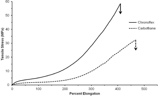
Stress vs. strain curves for neat polyurethane films
Table 2.
Tensile and biomechanical properties of the different poly (carbonate urethanes). Electrospun mesh thickness = 0.4 mm; n=4; mean ± standard deviation displayed
| Tensile Properties | ||
|---|---|---|
|
| ||
| Polymer | Initial Modulus (MPa) | Tensile Strength (MPa) |
| Carbothane | 7.1 ± 0.4 | 33.9 ± 4.7 |
| Chronoflex | 19.8 ± 0.9 | 58.8 ± 5.8 |
|
| ||
| Electrospun Graft Properties | ||
|
| ||
| Polymer | Compliance (%/mmHg × 10−4) | Burst Pressure (mmHg) |
|
| ||
| Carbothane | 3.8 ± 0.3 | 1330 ± 70 |
| Chronoflex | 2.4 ± 0.4 | 1680 ± 210 |
3.2 Effects of Material Chemistry on Biomechanical Properties
Electrospun graft biomechanical properties (burst pressure and compliance) were investigated to elucidate relationships between tensile and biomechanical properties. The tensile and biomechanical properties of the two polymers are summarized in Table 2. As often observed in the literature, grafts with higher compliance values also possessed lower burst pressures.31–33 Compliance was correlated to polyurethane initial modulus with lower initial modulus resulting in increased compliance. Similarly, burst pressure was correlated to tensile strength with higher tensile strength resulting in higher burst pressure (Figure 2). These findings suggest that polyurethanes with low initial modulus and high tensile strength have greater potential to be fabricated into an electrospun vascular graft with improved compliance while maintaining burst pressure. By this measure, Carbothane was selected for subsequent studies on modulating graft microarchitecture.
Figure 2.
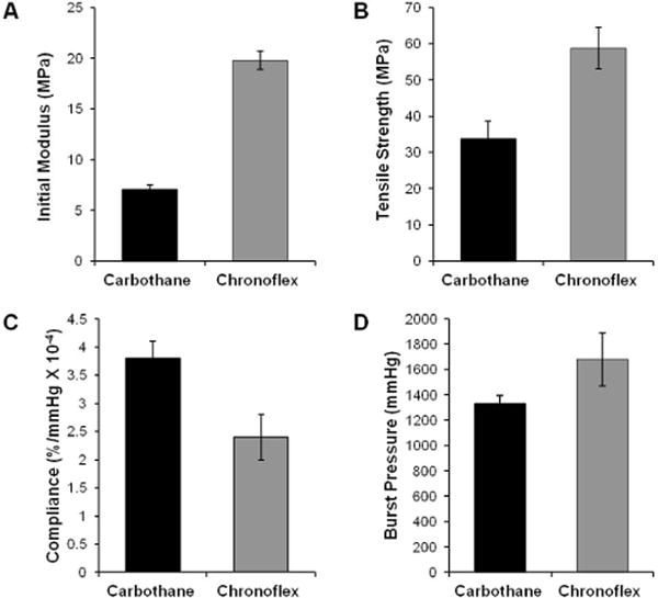
Tensile properties of poly (carbonate urethanes): (A) initial modulus and (B) tensile strength. Biomechanical properties of electrospun meshes (0.4 mm thickness) fabricated from different polyurethanes: (C) compliance and (D) burst pressure.
3.3 Electrospun Graft Microarchitecture
Scanning electron micrographs of the electrospun grafts display the characteristic fibrous microstructure with uniform fiber diameter (1.3 ± 0.1 μm) (Figure 3). Altered collection time was used to modulate graft wall thickness with collection times of 4, 5, and 6 hours corresponding to graft thicknesses of 0.4, 0.5, and 0.6 mm, respectively (Figure 4). Grafts with low fiber tortuosity (1.2 ± 0.4) compared to as-spun fiber tortuosity (1.7 ± 0.8) were achieved by increasing the mandrel rotation rate to 4000 rpm and placing a row of vertically aligned and negatively charged razor blades behind the rotating mandrel (Figure 5). Fiber alignment using a similar rotating mandrel setup has been reported previously.34–36 The addition of aligned razor blades was used to enhance fiber alignment and was determined necessary to reduce fiber tortuosity in this electrospinning setup.26, 27 Fiber fusions at intersections were induced by placing as-spun grafts in the presence of solvent vapor that induced swelling of the polyurethane and enhanced fusion at junctions without loss of fibrous architecture (Figure 6). A method was utilized to quantify the level of fusion using SEM analysis of fiber junctions. After incubation in DMAc vapor, meshes were generated with increased fusion at junctions, roughly 50% completely fused, 30% partially fused, and 20% non-fused fibers. Grafts after heat treatment were also characterized by increased fiber fusion to a lower extent with the amount of fusion increasing with length of heat treatment (Figure 7). Meshes undergoing heat treatment for 24 hours had roughly 2% completely fused, 32% partially fused, and 66% non-fused fibers. The individual and synergistic effects of these variations in microarchitecture on biomechanical properties were then investigated.
Figure 3.
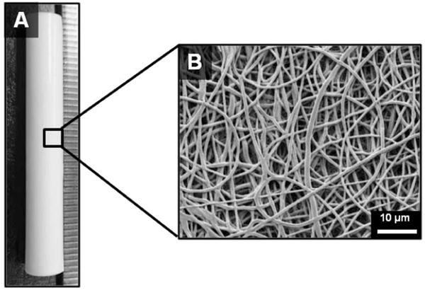
(A) Tubular electrospun mesh fabricated by electrospinning onto a rotating mandrel and (B) representative scanning electron micrograph of the fiber morphology.
Figure 4.

Scanning electron micrographs of electrospun mesh tubes with varying thicknesses. Cross-sectional views of (A) low thickness tube (wall thickness = 0.4 mm), (B) medium thickness tube (wall thickness = 0.5 mm), and (C) high thickness tube (wall thickness = 0.6 mm).
Figure 5.
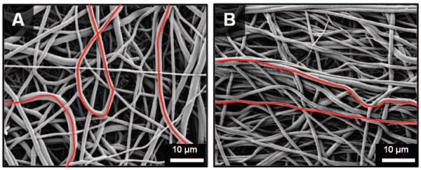
Scanning electron micrographs of electrospun meshes with different degrees of tortuosity: (A) high tortuosity and (B) low tortuosity.
Figure 6.
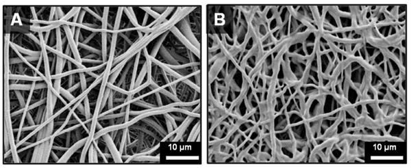
Scanning electron micrographs of electrospun meshes with different amounts of fiber fusion at junctions: (A) low fustion at junctions and (B) high fusion at junctions.
Figure 7.
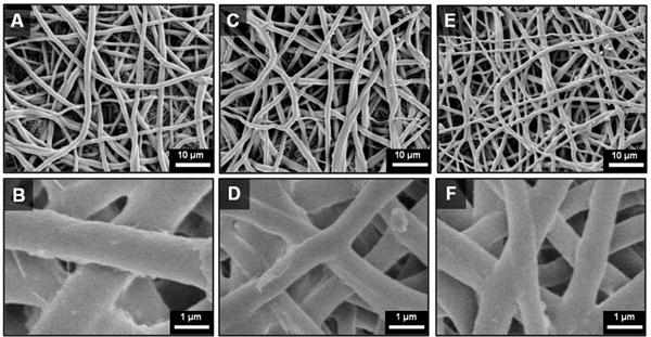
Scanning electron micrographs heat-treated Carbothane grafts: (A–B) Before heat treatment (C–D) After 12 hr heat treatment (E–F) After 24 hr heat treatment
3.4 Effects of Graft Microarchitecture on Biomechanical Properties
Effects of Mesh Thickness
Biomechanical properties for Carbothane meshes with decreasing wall thickness from 0.6 to 0.4 mm are summarized in Figure 8. Compliance values for meshes 0.6, 0.5, and 0.4 mm thick were 1.3 ± 0.6, 2.1 ± 0.4, and 3.8 ± 0.3 %/mmHg × 10−4, respectively (1 mmHg = 0.133 kPa). The corresponding burst pressures for meshes 0.6, 0.5, and 0.4 mm thick were 1560 ± 170, 1470 ± 40, 1330 ± 70 mmHg, respectively. It was hypothesized that decreased mesh thickness resulted in a decreased circumferential stress that resulted in the observed increases in compliance and decreases in burst pressure. Importantly, large increases in compliance were achieved with only small sacrifices in burst pressure, suggesting the potential to improve compliance while maintaining a sufficient burst pressure. For example, when mesh thickness was decreased from 0.6 mm to 0.5 mm, a 63% increase in compliance was achieved with only a 6% loss in burst pressure. Further reduction of mesh thickness to 0.4 mm resulted in an 83% increase in compliance and a 9% loss in burst pressure. By altering mesh thickness alone, a compliance that approaches the saphenous vein was achieved with burst pressure only 21% lower than the saphenous vein (saphenous vein burst pressure: 1680 ± 310 mmHg7 and compliance: 4.4 ± 0.8 %/mmHg × 10−4 3). These results suggest the potential for improved arterial matching through modulation of graft fabrication parameters.
Figure 8.
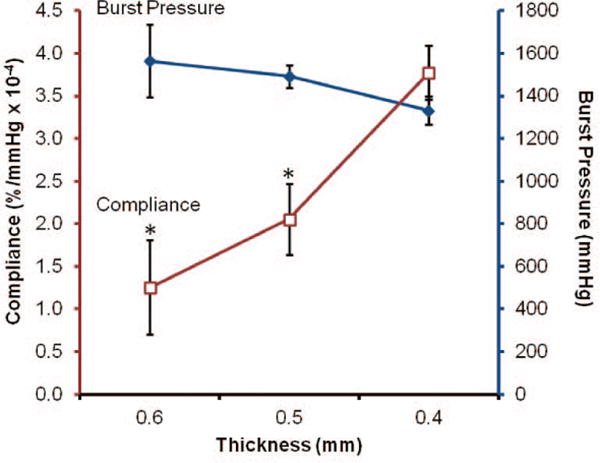
Biomechanical properties of Carbothane meshes with varying thicknesses (□ compliance and ◆ burst pressure). Note: decreasing thickness from left to right. *statistically different from 0.4 mm (p<0.01)
Effects of Fiber Tortuosity
The biomechanical properties of grafts with decreased tortuosity and fusions compared to control electrospun meshes are summarized in Figure 9. An increase in burst pressure and corresponding decrease in compliance were observed in the grafts with decreased tortuosity. Burst pressure was improved to 2190 ± 110 mmHg compared to 1330 ± 70 mmHg for the control, which also exceeded the saphenous vein autograft. Compliance decreased from the as-spun control values of 3.8 ± 0.3 %/mmHg × 10−4 to 2.6 ± 1.3 %/mmHg × 10−4. Electrospun fiber meshes have been described as tortuous networks which transform into interconnected web-like architectures when strained.37 These tortuous fibers were observed to change their direction of orientation under an applied load. Therefore, we hypothesized that tortuous fibers have the ability to elongate under small applied loads before being constrained by fiber junctions, resulting in increased compliance. In this case, the increased burst pressure and decreased compliance observed with decreased tortuosity was attributed to the increased alignment of the fibers. These findings are supported by literature reports that aligned fibers have increased modulus and tensile strength (properties correlating to decreased compliance and increased burst pressure) compared to randomly oriented fibers when stressed in the direction of alignment.38
Figure 9.
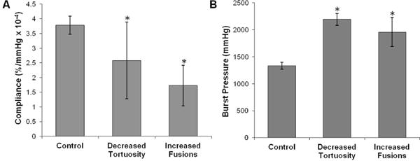
(A) Compliance and (B) burst pressure of Carbothane grafts with decreased tortuosity and fusions compared to control grafts. Electrospun meshes are all 0.4 mm thick. *statistically different from controls (p<0.01)
Effects of Fiber Fusion
Biomechanical testing of grafts with solvent-induced fusions created via incubation in DMAc vapor resulted in increased burst pressure and decreased compliance. Burst pressure greater than the saphenous vein autograft and the as-spun control was achieved in the meshes with increased fiber fusion (1960 ± 270 mmHg). As expected, there was a decrease in compliance from the as-spun control value of 3.8 ± 0.3 %/mmHg × 10−4 to 1.7 ± 0.7 %/mmHg × 10−4. Literature has shown that increased amount of fiber intersections results in increased modulus and ultimate elongation in the circumferential axis of a tubular graft.39–41 The induction of fiber fusions introduces a physical connection between fibers with chain entanglements that restricts dilation and results in increased burst pressure.
The biomechanical properties of the heat treated (24 hr) electrospun grafts are summarized in Figure 10. Heat treatment resulted in an increase in compliance to 6.0 ± 0.6 %/mmHg × 10−4 and an increase in burst pressure to 2260 ± 160 mmHg. By fabricating heat induced fusions into electrospun meshes, a vascular graft with both compliance and burst pressure that exceeded the saphenous vein autograft was achieved. Burst pressure increases similarly to the grafts with fusions via solvent vapor; however, the increase in compliance observed was attributed to changes in the polyurethane morphology. It is well established that thermal annealing provides energy to alter polyurethane microphase morphology.28, 42 Dynamic mechanical analysis (DMA) was used in this study to examine the effect of heat treatment on polyurethane phase morphology. Storage moduli of as-spun grafts, heated for 12 hours, heated for 24 hours, and with solvent-induced fusions are summarized in Figure 11. Both the as-spun and solvent induced fusions storage moduli were characterized by a lower plateau modulus, broad Tg transition, and melting transition (Tm) from 30–40 °C attributed to melting of crystalline soft domains.43 In contrast, the heat-treated meshes exhibited a higher plateau modulus, sharper Tg transition, and reduced (12 hr) or eliminated (24 hr) melting transition. These data indicate a reduction in soft segment crystallinity and an increase in phase separation in the electrospun meshes after heat treatment which was not observed for meshes with solvent-induced fiber fusions. This reduction in soft segment crystallinity was confirmed using DSC. Minimal change in crystallinity was observed after 12 hr heat treatment whereas a reduction in crystallinity and formation of higher order crystals occurs after 24 hr heat treatment, Figure 12.
Figure 10.
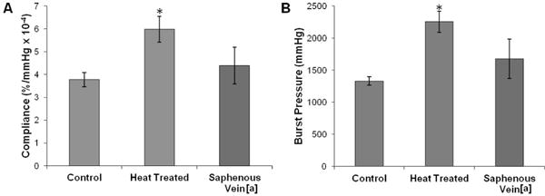
(A) Compliance and (B) burst pressure of Carbothane grafts with and without heat treatment compared to the saphenous vein. *statistically different from control (p<0.01). [a] values from Salacinski, et al. “The mechanical behavior of vascular grafts: a review.” Journal of Biomaterials Applications 2001;15:241.
Figure 11.
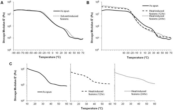
Storage moduli of electrospun Carbothane grafts (A) with solvent-induced fusions and (B) heat-induced fusions. (C) Change in melting transition with heat treatment.
Figure 12.
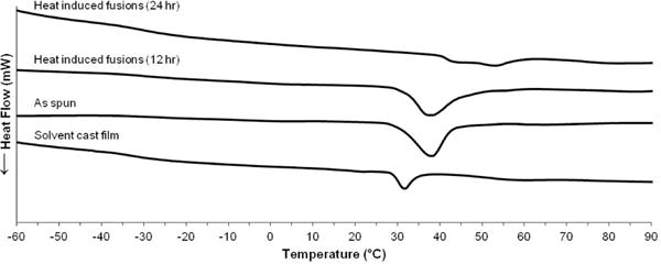
Differential scanning calorimetry thermograms of heat treated Carbothane electrospun meshes compared to as spun and neat film controls
Previous studies have reported soft segment crystallization of electrospun polycaprolactone polyurethanes due to alignment of polymer chains during the electrospinning process.44, 45 We hypothesize that similar soft segment crystallization of the electrospun polyurethane grafts in these studies could introduce rigid physical crosslinks that are lost upon heat treatment, resulting in a more compliant graft. This is supported by the loss of the melting transition after heat treatment and was confirmed using DSC. Compared to a solvent cast film, as spun electrospun meshes have greater soft segment crystallinity and higher order crystals, Figure 12. In addition, electrospinning results in poor phase separation of polyurethanes due to rapid drying of the fibers which does not provide sufficient time for well-ordered hard domains to form.44, 45 The increased phase separation indicated by the reduction in Tg breadth after annealing was hypothesized to result in decreased modulus which we previously correlated to an increase in compliance. Overall, the observed increase in compliance was attributed to a morphological change (increased phase separation and reduced soft segment crystallinity) and the increase in burst pressure was attributed to a change in mesh microarchitecture (increased fiber fusions). To the best of our knowledge, this is the first record of a small diameter vascular graft with both compliance and burst pressure exceeding the saphenous vein autograft.
4. Conclusions
These studies illustrate methods to fabricate electrospun vascular grafts with improved compliance while maintaining sufficient burst pressure by altering segmented polyurethane chemistry and electrospun mesh microarchitecture. Tensile testing and electrospun graft biomechanical testing elucidated relationships for rational selection of polymers based on commonly reported tensile properties. A polymer with low modulus and high tensile strength correlated to a vascular graft with high compliance and burst pressure. The effects of mesh thickness, fiber tortuosity, and fiber fusions at junctions on biomechanical properties were investigated to identify microarchitecture variables that have the most profound effect on biomechanical properties. Heat treatment was identified as the most promising method to enhance both compliance and burst pressure by enhancing microphase separation and inducing fiber fusions. In this way, an electrospun small diameter synthetic vascular graft with compliance and burst pressure exceeding the saphenous vein autograft was fabricated for the first time. This graft has the potential to reduce intimal hyperplasia associated with low compliance in synthetic grafts and improve long term clinical success. Additionally, the fundamental relationships between electrospun mesh microarchitecture and mechanical properties identified in this work can be utilized in various tissue engineering applications.
Although this work illustrates the potential of synthetic electrospun vascular grafts for improved long term clinical success, extensive investigation remains prior to clinical usage. These vascular grafts improve upon current synthetic options by exceeding the compliance of the saphenous vein autograft; however, further improvements can be implemented with the goal of achieving values comparable to arterial grafts. The internal mammary artery, also a current clinical standard, has a compliance of 11.5 ± 3.9 %/mmHg × 10−4.46 The structure-property relationships elucidated in this work provide the tools necessary to design a second generation of grafts with arterial compliance values. As with most synthetic materials, these grafts are inherently thrombogenic and when implanted alone would require medical intervention. To overcome this limitation, the ultimate graft design incorporates an inner layer composed of a bioactive, thromboresistant hydrogel.24 As these grafts are intended for long term implantation, the effects of sterilization and storage as well as biostability warrant evaluation. Future in vivo studies in a porcine animal model will be performed to assess the ability to resist intimal hyperplasia and resultant long term patency of these vascular grafts.
Acknowledgments
This work was supported by NIH R01 EB013297 and the Texas A&M University Diversity Fellowship. The authors graciously acknowledge Dr. Melissa Grunlan for use of her differential scanning calorimeter.
Contributor Information
Roya M. Nezarati, Email: roya.nezarati@gmail.com.
Michelle B. Eifert, Email: mbeifert@gmail.com.
David K. Dempsey, Email: davedempsey1@gmail.com.
Elizabeth Cosgriff-Hernandez, Email: cosgriff.hernandez@tamu.edu.
References
- 1.Roger VL, Go AS, Lloyd-Jones DM, Adams RJ, Berry JD, Brown TM, Carnethon MR, Dai S, Simone Gd, Ford ES, Fox CS, Fullerton HJ, Gillespie C, Greenlund KJ, Hailpern SM, Heit JA, Ho PM, Howard VJ, Kissela BM, Kittner SJ, Lackland DT, Lichtman JH, Lisabeth LD, Makuc DM, Marcus GM, Marelli A, Matchar DB, McDermott MM, Meigs JB, Moy CS, Mozaffarian D, Mussolino ME, Nichol G, Paynter NP, Rosamond WD, Sorlie PD, Stafford RS, Turan TN, Turner MB, Wong ND, Wylie-Rosett J. Heart disease and stroke statistics–2011 update: a report from the American Heart Association. Circulation. 2011;123:e18–e209. doi: 10.1161/CIR.0b013e3182009701. [DOI] [PMC free article] [PubMed] [Google Scholar]
- 2.Goldman S, Sethi GK, Holman W, Thai H, McFalls E, Ward HB, Kelly RF, Rhenman B, Tobler GH, Bakaeen FG, Huh J, Soltero E, Moursi M, Haime M, Crittenden M, Kasirajan V, Ratliff M, Pett S, Irimpen A, Gunnar W, Thomas D, Fremes S, Moritz T, Reda D, Harrison L, Wagner TH, Wang YJ, Planting L, Miller M, Rodriguez Y, Juneman E, Morrison D, Pierce MK, Kreamer S, Shih MC, Lee K. Radial artery grafts vs saphenous vein grafts in coronary artery bypass surgery a randomized trial. JAMA, J Am Med Assoc. 2011;305:167–74. doi: 10.1001/jama.2010.1976. [DOI] [PubMed] [Google Scholar]
- 3.Salacinski H, Goldner S, Giudiceandrea A, Hamilton G, Seifalian A. The mechanical behavior of vascular grafts: a review. J Biomater Appl. 2001;15:241–78. doi: 10.1106/NA5T-J57A-JTDD-FD04. [DOI] [PubMed] [Google Scholar]
- 4.Green RM, Abbott WM, Matsumoto T, Wheeler JR, Miller N, Veith FJ, Money S, Edward Garrett H. Prosthetic above-knee femoropopliteal bypass grafting: Five-year results of a randomized trial. Journal of Vascular Surgery. 2000;31:417–25. [PubMed] [Google Scholar]
- 5.Clowes A, Gown A, Hanson S, Reidy M. Mechanisms of arterial graft failure 1. Role of cellular proliferation in early healing of PTFE prostheses. Am J Pathol. 1985;118:43–54. [PMC free article] [PubMed] [Google Scholar]
- 6.Greenwald SE, Berry CL. Improving vascular grafts: the importance of mechanical and haemodynamic properties. Journal of Pathology. 2000;190:292. doi: 10.1002/(SICI)1096-9896(200002)190:3<292::AID-PATH528>3.0.CO;2-S. [DOI] [PubMed] [Google Scholar]
- 7.L’Heureux N, Stoclet J-C, Auger FA, Lagaud GJ-L, Germain L, Andriantsitohaina R. A human tissue-engineered vascular media: a new model for pharmacological studies of contractile responses. The FASEB Journal. 2001;15:515–24. doi: 10.1096/fj.00-0283com. [DOI] [PubMed] [Google Scholar]
- 8.Silver FH, Snowhill PB, Foran DJ. Mechanical behavior of vessel wall: a comparative study of aorta, vena cava, and carotid artery. Ann Biomed Eng. 2003;31:793–803. doi: 10.1114/1.1581287. [DOI] [PubMed] [Google Scholar]
- 9.Christenson EM, Anderson JM, Baer E, Hiltner A. Relationship between nanoscale deformation process and elastic behavior of polyurethane elastomers. Polymer. 2005;46:11744–54. [Google Scholar]
- 10.Eberhart A, Zhang Z, Guidoin R, Laroche G, Guay L, De La Faye D, Batt M, King MW. A new generation of polyurethane vascular prostheses: rara avis or ignis fatuus? J Biomed Mater Res. 1999;48:546–58. doi: 10.1002/(sici)1097-4636(1999)48:4<546::aid-jbm22>3.0.co;2-v. [DOI] [PubMed] [Google Scholar]
- 11.Tiwari A, Salacinski H, Seifalian AM, Hamilton G. New prostheses for use in bypass grafts with special emphasis on polyurethanes. Cardiovasc Surg. 2002;10:191–7. doi: 10.1016/s0967-2109(02)00004-2. [DOI] [PubMed] [Google Scholar]
- 12.Sarkar S, Burriesci G, Wojcik A, Aresti N, Hamilton G, Seifalian AM. Manufacture of small calibre quadruple lamina vascular bypass grafts using a novel automated extrusion-phase-inverison method and nanocomposite polymer. J Biomech. 2009;42:722–30. doi: 10.1016/j.jbiomech.2009.01.003. [DOI] [PubMed] [Google Scholar]
- 13.Madhavan K, Reddy BSR. Synthesis and characterization of poly(dimethylsiloxane-urethane) elastomers: Effect of hard segments of polyurethane on morphological and mechanical properties. J Polym Sci, Part A: Polym Chem. 2006;44:2980–9. [Google Scholar]
- 14.Miller J, Lin S, Hwang K, Wu K, Gibson P, Cooper S. Properties of polyether-polyurethane block copolymers: effects of hard segment length distribution. Macromolecules. 1985;18:32–44. [Google Scholar]
- 15.Pham QP, Sharma U, Mikos AG. Electrospinning of polymeric nanofibers for tissue engineering applications: a review. Tissue Eng. 2006;12:1197–211. doi: 10.1089/ten.2006.12.1197. [DOI] [PubMed] [Google Scholar]
- 16.Ramakrishna S, Fujihara K, Teo W, Lim T, Ma Z. An introduction to electrospinning and nanofibers. Singapore: World Scientific Publishing Co. Pte. Ltd; 2005. [Google Scholar]
- 17.Doshi J, Reneker DH. Electrospinning process and applications of electrospun fibers. J Electrost. 1995;35:151–60. [Google Scholar]
- 18.Lee SJ, Yoo JJ, Lim GJ, Atala A, Stitzel J. In vitro evaluation of electrospun nanofiber scaffolds for vascular graft application. J Biomed Mater Res, Part A. 2007;83A:999–1008. doi: 10.1002/jbm.a.31287. [DOI] [PubMed] [Google Scholar]
- 19.Bini T, Gao S, Tan T, Wang S, Lim A, Hai L, Ramakrishna S. Electrospun poly(L-lactide-co-glycolide) biodegradable polymer nanofibre tubes for peripheral nerve regeneration. Nanotechnology. 2004;15:1459–64. [Google Scholar]
- 20.Lee K, Kim H, Ryu Y, Kim K, Choi S. Mechanical behavior of electrospun fiber mats of poly(vinyl chloride)/polyurethane polyblends. J Polym Sci, Part B Polym Phys. 2003;41:1256–62. [Google Scholar]
- 21.Tan EPS, Ng SY, Lim CT. Tensile testing of a single ultrafine polymeric fiber. Biomaterials. 2005;26:1453–6. doi: 10.1016/j.biomaterials.2004.05.021. [DOI] [PubMed] [Google Scholar]
- 22.Wong S-C, Baji A, Leng S. Effect of fiber diameter on tensile properties of electrospun poly(ε-caprolactone) Polymer. 2008;49:4713–22. [Google Scholar]
- 23.Stylianopoulos T, Bashur C, Goldstein A, Guelcher SA, Barocas V. Computational predictions of the tensile properties of electrospun fibre meshes: Effect of fibre diameter and fibre orientation. J Mech Behav Biomed Mater. 2008;1:326–35. doi: 10.1016/j.jmbbm.2008.01.003. [DOI] [PMC free article] [PubMed] [Google Scholar]
- 24.Browning MB, Dempsey D, Guiza V, Becerra S, Rivera J, Russell B, Höök M, Clubb F, Miller M, Fossum T, Dong JF, Bergeron AL, Hahn M, Cosgriff-Hernandez E. Multilayer vascular grafts based on collagen-mimetic proteins. Acta Biomaterialia. 2012;8 doi: 10.1016/j.actbio.2011.11.015. [DOI] [PubMed] [Google Scholar]
- 25.Nezarati R, Eifert M, Cosgriff-Hernandez E. Effects of humidity and solution viscosity on electrospun fiber morphology. Tissue Eng, Part C. 2013;19:1–10. doi: 10.1089/ten.tec.2012.0671. [DOI] [PMC free article] [PubMed] [Google Scholar]
- 26.Teo W, Kotaki M, Mo X, Ramakrishna S. Porous tubular structures with controlled fibre orientation using a modified electrospinning method. Nanotechnology. 2005;16:918–24. [Google Scholar]
- 27.Teo W, Ramakrishna S. Electrospun fibre bundle made of aligned nanofibres over two fixed points. Nanotechnology. 2005;16:1878–84. [Google Scholar]
- 28.Li Y, Ren Z, Zhao M, Yang H, Chu B. Multiphase structure of segmented polyurethanes: effects of hard-segment flexibility. Macromolecules. 1993;26:612–22. [Google Scholar]
- 29.Ng HN, Allegrezza AE, Seymour RW, Cooper SL. Effect of segment size and polydispersity on the properties of polyurethane block polymers. Polymer. 1973;14:255–61. [Google Scholar]
- 30.Lee D-K, Tsai HB. Properties of segmented polyurethanes derived from different diisocyanates. J Appl Polym Sci. 2000;75:167–74. [Google Scholar]
- 31.Soletti L, Hong Y, Guan J, Stankus JJ, El-Kurdi MS, Wagner WR, Vorp DA. A bilayered elastomeric scaffold for tissue engineering of small diameter vascular grafts. Acta Biomater. 2010;6:110–22. doi: 10.1016/j.actbio.2009.06.026. [DOI] [PMC free article] [PubMed] [Google Scholar]
- 32.Rodriguez M, Juran C, McClendon M, Eyadiel C, McFetridge PS. Development of a mechanically tuneable 3D scaffold for vascular reconstruction. J Biomed Mater Res, Part A. 2012;100A:3480–9. doi: 10.1002/jbm.a.34267. [DOI] [PMC free article] [PubMed] [Google Scholar]
- 33.Doi K, Nakayama Y, Matsuda T. Novel compliant and tissue-permeable microporous polyurethane vascular prosthesis fabricated using an excimer laser ablation technique. J Biomed Mater Res. 1996;31:27–33. doi: 10.1002/(SICI)1097-4636(199605)31:1<27::AID-JBM4>3.0.CO;2-S. [DOI] [PubMed] [Google Scholar]
- 34.Yang F, Murugan R, Wang S, Ramakrishna S. Electrospinning of nano/micro scale poly(L-lactic acid) aligned fibers and their potential in neural tissue engineering. Biomaterials. 2005;26:2603–10. doi: 10.1016/j.biomaterials.2004.06.051. [DOI] [PubMed] [Google Scholar]
- 35.Subramanian A, Krishnan U, Sethuraman S. Fabrication, characterization and in vitro evaluation of aligned PLGA–PCL nanofibers for neural regeneration. Ann Biomed Eng. 2012;40:2098–110. doi: 10.1007/s10439-012-0592-6. [DOI] [PubMed] [Google Scholar]
- 36.Xu C, Inai R, Kotaki M, Ramakrishna S. Aligned biodegradable nanofibrous structure: a potential scaffold for blood vessel engineering. Biomaterials. 2004;25:877–86. doi: 10.1016/s0142-9612(03)00593-3. [DOI] [PubMed] [Google Scholar]
- 37.Stella J, Wagner W, Sacks M. Scale-dependent fiber kinematics of elastomeric electrospun scaffolds for soft tissue engineering. J Biomed Mater Res, Part A. 2009;93A:1032–42. doi: 10.1002/jbm.a.32593. [DOI] [PMC free article] [PubMed] [Google Scholar]
- 38.Lee C, Shin H, Cho I, Kang Y, Kim I, Park K, Shin J. Nanofiber alignment and direction of mechanical strain affect the ECM production of human ACL fibroblast. Biomaterials. 2005;26:1261–70. doi: 10.1016/j.biomaterials.2004.04.037. [DOI] [PubMed] [Google Scholar]
- 39.Amoroso NJ, D’Amore A, Hong Y, Wagner WR, Sacks MS. Elastomeric electrospun polyurethane scaffolds: the interrelationship between fabrication conditions, fiber topology, and mechanical properties. Adv Mater. 2011;23:106–11. doi: 10.1002/adma.201003210. [DOI] [PMC free article] [PubMed] [Google Scholar]
- 40.Engelmayr JGC, Sacks MS. A structural model for the flexural mechanics of nonwoven tissue engineering scaffolds. J Biomech Eng. 2006;128:610–22. doi: 10.1115/1.2205371. [DOI] [PubMed] [Google Scholar]
- 41.Amoroso NJ, D’Amore A, Hong Y, Rivera CP, Sacks MS, Wagner WR. Microstructural manipulation of electrospun scaffolds for specific bending stiffness for heart valve tissue engineering. Acta Biomater. 2012;8:4268–77. doi: 10.1016/j.actbio.2012.08.002. [DOI] [PMC free article] [PubMed] [Google Scholar]
- 42.Leung LM, Koberstein JT. DSC annealing study of microphase separation and multiple endothermic behavior in polyether-based polyurethane block copolymers. Macromolecules. 1986;19:706–13. [Google Scholar]
- 43.Eceiza A, Larranaga M, de la Caba K, Kortaberria G, Marieta C, Corcuera MA, Mondragon I. Structure–Property Relationships of Thermoplastic Polyurethane Elastomers Based on Polycarbonate Diols. Journal of Applied Polymer Science. 2007;1087 [Google Scholar]
- 44.Zhuo H, Hu J, Chen S. Electrospun polyurethane nanofibres having shape memory effect. Mater Lett. 2008;62:2074–6. [Google Scholar]
- 45.Zhuo H, Hu J, Chen S, Yeung L. Preparation of polyurethane nanofibers by electrospinning. J Appl Polym Sci. 2008;109:406–11. [Google Scholar]
- 46.Konig G, McAllister TN, Dusserre N, Garrido SA, Iyican C, Marini A, Fiorillo A, Avila H, Wystrychowski W, Zagalski K, Maruszewski M, Jones AL, Cierpka L, de la Fuete LM, L’Heureux Mechanical properties of completely autologous human tissue engineered blood vessels compared to human saphenous vein and mammary artery. Biomaterials. 2009;30 doi: 10.1016/j.biomaterials.2008.11.011. [DOI] [PMC free article] [PubMed] [Google Scholar]


