Abstract
Transition from latency to active tuberculosis requires Mycobacterium tuberculosis (Mtb) to penetrate the phagosomal membrane and translocate to the cytosol of the host macrophage. Quantitative two-photon fluorescence resonance energy transfer (FRET) microscopy is developed to measure cytosolic translocation using Mycobacterium marinum (Mm) as a model organism for Mtb. Macrophages were infected with Mm or non-pathogenic Mycobacterium smegmatis (Ms) as a control, then loaded with a FRET substrate. Once translocation occurs, mycobacterium-bearing β-lactamase cleaves the substrate, resulting in decrease of FRET signal. Quantification of this FRET signal change revealed that Mm, but not Ms, is capable of translocating to the cytosol.
OCIS codes: (170.2520) Fluorescence microscopy, (170.1530) Cell analysis
1. Introduction
It is estimated that one-third of the world’s population is latently infected with Mycobacterium tuberculosis (Mtb), and 5-10% of these latently infected individuals develop into active tuberculosis, which results in over 2 million deaths each year [1]. Transition from latency to active tuberculosis is a critical step in pathogenesis of Mtb. Current studies have suggested that the transition requires Mtb to penetrate phagosomal membrane and translocate to the cytosol of the host macrophage (termed “cytosolic translocation”), where Mtb replicates and spreads to other cells through cytolysis [2–4]. However, the cellular and molecular mechanisms of Mtb cytosolic translocation are not clear. Here, we use Mycobacterium marinum (Mm) as a surrogate model organism to study the mechanisms of mycobacterial cytosolic translocation. Mm causes tuberculosis-like diseases in fish, and it is also able to infect immune-competent humans where it induces formation of dermal granulomas pathologically similar to those formed in tuberculosis [5]. More importantly, Mm has a highly-conserved ESX-1 secretion system, which has been shown to play an essential role in cytosolic translocation of both Mtb and Mm [6]. Compared to Mtb, Mm is safer and more amenable, which will facilitate research progress.
Fluorescence resonance energy transfer (FRET) imaging has been used to monitor vacuole membrane rupture by bacteria [7, 8]. In this approach a bacterial β–lactamase-sensitive FRET reporter CCF4-AM [9], is loaded into the cell. The fluorescence donor in CCF4-AM is 7-hydroxycoumarin (blue), and the acceptor is fluorescein (green). They are linked by a cephalosporin core, which is a cleavable substrate of bacterial β–lactamase. CCF4-AM can diffuse freely across the plasma membranes and enter the cytosol. Upon entering the cell, CCF4-AM is cleaved by endogenous cytoplasmic esterases, and converts into its negatively charged form, CCF4, an anionic molecule that is irreversibly trapped in the cytosol and excluded from endosomes and other organelles [10]. After bacteria disrupt the phagosomal membrane, bacterial β–lactamase cleaves CCF4 at the cephalosporin core, which breaks the donor and the acceptor apart and results in loss of FRET signal. By monitoring this FRET signal change, researchers have studied the spatial and temporal progress in pathogen-induced vacuole rupture. Simeone et al. observed cytosolic translocation of wild type Mtb strain, whereas the strains with deletion or truncation in ESX-1 secretion system remained enclosed within the phagosomal compartment [3].
In this study, we developed a two-photon excited FRET imaging method with the intention that two-photon excitation has the advantages of reduced photobleaching, photodamage and phototoxicity [11–13].
2. Two-photon FRET microscope
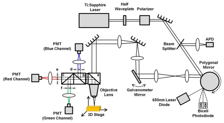
The schematic drawing of the two-photon FRET microscope is shown in Fig. 1 . The laser source is a mode-locked Ti:Sapphire laser (Maitai HP, wavelength 690-1040 nm, 100 fs pulse width, 80 MHz repetition rate, Spectra-Physics, Santa Clara, CA). We have used 710 nm light to achieve two-photon excitation on the donor, 7-hydroxycoumarin. The laser beam is fed into a home-built video-rate (30 frames/second) x-y scanner (polygon, galvanometer). The beam passes through a dichroic beam splitter (FF665-Di02, Semrock, Rochester, NY) and is then focused onto the sample by a 60 × , NA = 1.2, water-immersion microscope objective lens (UPLSAPO60 × W, Olympus USA, Center Valley, PA). The laser power at the sample site is 10 mW. The fluorescence signal from the sample is deflected with the 665 nm long-pass dichroic mirror. A second long-pass dichoric beam splitter (FF495-Di03, Semrock, Rochester, NY) is used to split the blue and green/red fluorescence signal. The blue signal is deflected by the second dichroic beam splitter, and then is transmitted through a 417-477 nm band-pass filter (FF02-447/60, Semrock, Rochester, NY), and finally is detected by a photomultiplier tube (PMT) (R10699, Hamamatsu, Bridgewater, NJ). A third long-pass dichroic beam splitter (FF580FDi01, Semrock, Rochester, NY) is used to split the green and red fluorescence signal. The green signal is transmitted through a 500-550 nm band-pass filter (FF03-525/50, Semrock, Rochester, NY), and finally is detected by a photomultiplier tube (PMT) (R10699, Hamamatsu, Bridgewater, NJ). The red signal is transmitted through a 570-616 nm band-pass filter (FF01-593/46, Semrock, Rochester, NY), and finally is detected by a photomultiplier tube (PMT) (R3896, Hamamatsu, Bridgewater, NJ). The outputs of these three PMTs are fed into red/green/blue channels of a frame grabber (Solios eA/XA, Matrox, Quebec, Canada) installed on a computer. Two-dimensional images in x-y plane are acquired through a home-built software program. Each frame has 500 × 500 pixels. The imaging speed is 30 frames/sec and each final static image is an average of 50 frames. Details of this microscope design can be found in reference [14].
Fig. 1.
Two-photon FRET microscope setup (a, b, & c: dichroic beam splitters; d, e, & f: band-pass filters).
3. Image Processing
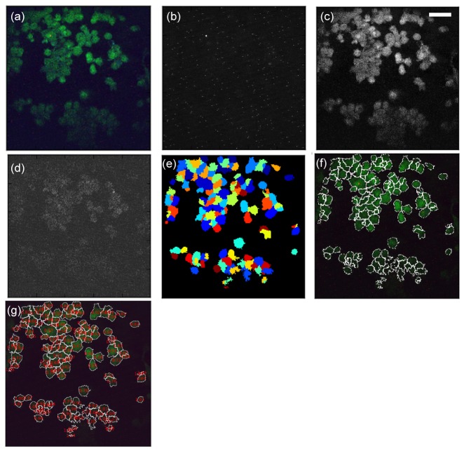
The images acquired with our two-photon microscope were saved as 24-bit RGB TIFF files. Each of them displays 8-bit (0-255) intensity values in the red, green and blue channels respectively. They were quantitatively analyzed using the CellProfiler software [15]. A pipeline was created in order to identify cells properly and calculate the ratio of the respective mean intensity in the blue and green channels per individual cell. The following steps are used to construct a pipeline to process large amount of images: image pre-processing (Step 1), cell identification (Step 2), measurement (Step 3), calculation (Step 4), image post-processing (Step 5), and result output (Step 6).
Step 1: RGB color images (Fig. 2(a) ) were converted to grayscale images by splitting the three channels into three individual grayscale images in R, G, and B respectively (Fig. 2(b)-2(d)). The green and blue channel images (Fig. 2(c) and 2(d)) are used for cell identification in Step 2; the red channel images only indicate the bacteria protein distribution.
Fig. 2.
Image processing and cell identification. (a) Original RGB image. (b) Grayscale image from red channel. (c) Grayscale image from green channel. (d) Grayscale image from blue channel. (e) Binary image with identified cells. (f) Cells with demarcated boundaries (g) RGB image with calculated B/G ratio displayed. (bar: 50 μm)
Step 2: Each image was smoothed with a Gaussian filter in order to remove high frequency noise. Using the images (Fig. 2(c) and 2(d)) generated in Step 1, a global threshold strategy, Otsu method [16], was used to classify pixel intensities as foreground (cell) or background. This method calculates the threshold separating the two classes of pixels based on splitting the image into three classes: foreground, mid-level, and background. The mid-level intensity class was also assigned to the foreground. Cells were further identified based on diameters in the range of 10 to 80 pixels (6.4 to 51.2 μm). Cells with size outside this range were discarded. Similarly, cells located on the border of the images were not taken into account to avoid measurements from a portion of an object. The identified cells are displayed as binary cells in Fig. 2(e) which are represented with colorful patches for better visualization. Cell boundaries are demarcated with white lines as shown in Fig. 2(f).
Step 3: The average pixel intensity in G and B respectively (Fig. 2(c) and 2(d)) was measured within each cell identified in Step 2. These measurements were converted from CellProfiler default scale (0 to 1) to grayscale (0 to 255). Cells with an average pixel intensity below or equal to the background average pixel intensity were discarded from the following analyses.
Step 4: The ratio of mean blue intensity over mean green intensity was calculated for each cell based on the measurements from Step 3.
Step 5: The ratios calculated in Step 4 were displayed on top of each cell in the grayscale green channel image (Fig. 2(g)).
Step 6: RGB color images displaying cell outlines and ratios from Steps 4 were saved as TIF files. The grayscale mean intensities in G and B generated in Step 3 together with the ratios from Step 4 were exported as text files.
4. Cell Culture Preparation and Infection
The following flow chart (Fig. 3 ) illustrates the overview of the experimental procedure.
Fig. 3.

Overview of the experimental procedure.
Infection
-
1.
Mm strain with deletion of cfp10/esat6 (MmΔc10/e6) was generated as previously described with modifications [17]. Deletion of cfp10/e6 was confirmed by PCR and western blotting analyses.
-
2.
To detect mycobacteria cells directly, Mm, MmΔc10/e6, and Ms cells were transformed with plasmid pMSP12::mCherry for constitutive expression of the red fluorescent protein mCherry. Transformants were selected on solid 7H10 agar medium supplemented with 30 µg/ml kanamycin. Single colonies were picked and grown to late-log phase (OD600 = 1.5-1.9) in liquid 7H9 medium supplemented with 10% ADC and 0.05% Tween-80 at 30 °C. The mycobacterial cells were harvested, washed, re-suspended in PBS and then passed through a 27-gauge syringe. Single-cell bacteria were obtained by passing through a 5-μm filter (Millipore). Bacterial concentration was determined by counting cells under a fluorescence microscope.
-
3.
RAW 267.4 mouse macrophage cells (60% confluence) were infected with Mm or Ms at an MOI of 10 in EM medium (25 mM HEPES at pH7.3, 120 mM NaCl, 7 mM KCl, 1.8 mM CaCl2, 0.8 mM MgCl2, 5 mM glucose). After 2 h of incubation at 32 °C, the medium was removed and the cells were washed 3 times to remove extracellular bacteria, which was followed by addition of fresh EM medium containing HEPES and 10% FBS. At 48 or 96 h post-infection, CCF4-AM FRET assays were performed as described below.
CCF4-AM FRET Assay
The assay was performed by following the product manual (Invitrogen K1095) with subtle modifications:
-
1.
Preparation of Solution A: Add 182 (912/5) µl of DMSO to dissolve 200 µg CCF4-AM. Aliquot the solution into 20 µl/tube, and store the aliquots at −20 °C, desiccated and protected from light. Before each use, allow the frozen stock solution to thaw at room temperature and remove the desired amount of reagent. To reduce moisture uptake, recap the vial immediately after each use and return it to the desiccator in the −20 °C freezer. Note: Stored under these conditions, Solution A is stable for at least three months. Once thawed, Solution A may appear slightly yellow. This color change does not affect the quality or function of the product.
-
2.
Preparation of 6 × CCF4-AM substrate loading solution
-
1).
Add 3 µl of Solution A to 30 µl of Solution B (100 mg/ml Pluronic®-F127 surfactant in DMSO and 0.1% acetic acid) and vortex.
-
2).
Add 467 µl of Solution C (24% w/w PEG 400, 18% TR-40 by volume in water) to the combined Solution A and B and vortex. Note: Under typical laboratory conditions, 6 × CCF4-AM substrate loading solution is stable for up to 12 hours.
-
1).
-
3.
Loading cells with substrate
-
1).
Add 6 × CCF4-AM substrate loading solution to cells (60-80% confluence is the best) to achieve 1 × final concentration (e.g., add 20 µl of 6 × CCF4-AM substrate loading solution to 100 µl of cells in buffer).
We made 500 µl of 6 × CCF4-AM substrate loading solution, mixed it with 2.5 ml of EM buffer. Then we added 250 µl of this mixed solution to each well.
-
2).
Cover the plate to protect it from light and evaporation.
-
3).
Incubate at room temperature for 120 minutes.
-
4).
Cells are washed by PBS and fixed with fresh 4% paraformaldehyde for 30 min at room temperature in the dark.
-
5).
Cells are washed with PBS again before performing fluorescence imaging.
-
1).
5. Results
Cellular Autofluorescence and CCF-4 Fluorescence Background
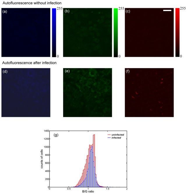
Cellular autofluorescence contributes to the background in FRET measurement. Therefore, the spare cells, which went through the same cell culture processes in Section 4 but without bacteria infection and CCF4-AM staining, were imaged under the two-photon microscope. The blue, green, and red fluorescence images were shown in Fig. 4(a) , 4(b), and 4(c) respectively. Both channels showed little fluorescent intensity. The quantitative measurement gave cellular background intensity around 30 in blue and green channels on a scale of 0-255 (8-bit A/D conversion of the PMT signal). And the cellular background intensity is around 40 in red channel. Cellular stress and apoptosis could possibly induce autofluorescence change. Therefore, we performed a control experiment to check cellular autofluorescence after pathogenic Mm infection (Fig. 4(d)-4(f)). Mouse macrophages were infected by the pathogenic Mm without CCF4-AM staining, and went through the same cell culture processes as the cells stained with CCF4-AM. The overall autofluorescence background for the infected cells (Fig. 4(d)-4(f)) had a slight increase compared with the uninfected cells (Fig. 4(a)-4(c)). This increase is uniform among all R, G, and B channels. Hence, the histogram of quantified B/G ratio is not changed as shown in Fig. 4(g). The bright red fluorescent patterns in Fig. 4(f) are from mCherry in bacteria, which is discussed in details later.
Fig. 4.
Cellular autofluorescence backgrounds are minimal in blue (a) & (d), green (b) & (d), and red (c) & (f) channels from the uninfected or the Mm-infected cells. (g) Histograms of blue/green ratio for the uninfected (red) and Mm-infected cells (blue) at 96 h post-infection. The total counted Mm-infected cells are 9430, and the total counted uninfected cells are 16010. (bar: 20 µm)
Next, after CCF4-AM was loaded into the cells, the fluorescence signal was checked as shown in Fig. 5 . The blue channel (Fig. 5(a)) showed a background similar to cellular autofluorescence. While the green channel (Fig. 5(b)) had a significant increase in intensity (typically over 100) compared with cellular autofluorescence (30-40). This indicates that CCF4-AM had been absorbed by macrophages and FRET was processed efficiently with the blue fluorescence being quenched.
Fig. 5.
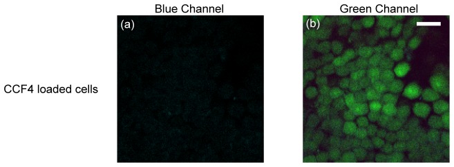
CCF4 fluorescence background of the macrophages shows that the blue intensity is on the same level of cellular autofluorescence (a), while green intensity is much higher (b), indicating efficient loading of CCF4-AM into cells. (bar: 20 µm)
FRET Imaging of Mm- vs. Ms-infected Macrophages
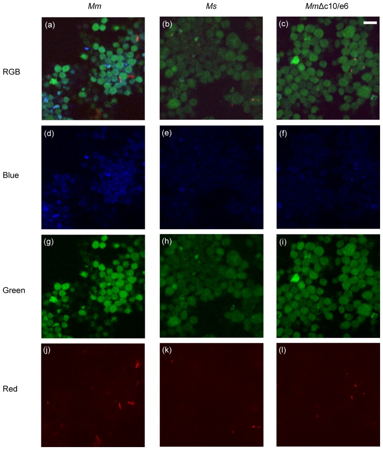
To observe the loss of FRET signal after mycobacteria rupture the phagosomal membrane, RAW 267.4 macrophages were infected with Mm. As a control, the macrophages were also infected by Mycobacterium smegmatis (Ms), a non-pathogenic mycobacterial species that is not able to rupture the phagosome membranes. At 96 h post-infection, the images of the donor (blue) and acceptor (green) fluorescence were taken and shown in Fig. 6 . Some of the Mm-infected macrophages showed significantly stronger blue florescence (Fig. 6(a) and 6(d)) than the Ms-infected cells (Fig. 6(b) and 6(e)). We also used the red channel to detect directly mycobacterial cells expressing the red fluorescent mCherry protein. As expected, the Mm-infected cells image (Fig. 6(j)) showed more red fluorescence than the Ms-infected cells image (Fig. 6(k)). More interestingly, the red fluorescence pattern from the Mm-infected cells showed patches (possible clusters of Mm bacteria), while there was dotty red fluorescence pattern from the Ms-infected cells. By correlating these red fluorescence images with the corresponding green fluorescence images, we found that there were more Mm-patches in the extracellular space (average 16 patches out of 5 randomly selected images) than the Ms-dots (average 8 dots out of 5 randomly selected images). This clearly indicated that Mm gained access to the cytosol and replicated, while majority of Ms were contained within phagosomes. We noticed that the blue fluorescence intensity from the Ms-infected cells was slightly higher than that from cellular autofluorescence, which could possibly be due to bacteria-induced apoptosis.
Fig. 6.
At 96 h post-infection, the cells infected with Mm show higher blue (d) and red (j) intensity than the cells infected with Ms ((e)-(k)), and the cells infected with MmΔc10/e6 ((f)-(l)) respectively. (bar: 20 µm)
To further confirm the result, we infected the macrophages with the Mm strain whose cfp10/esat6 genes were knocked out, termed MmΔc10/e6. It has been shown that deletion of cfp10/esat6 abolished the ability of Mm to rupture phagosome membrane and translocate to the cytosol [3]. As expected, the macrophages infected with MmΔc10/e6 show similar blue, green and red fluorescence (Fig. 6(f), 6(i), and 6(l)) as the Ms-infected cells. This result is consistent with the current studies that the ESX-1 secretion system, including cfp10/esat6, plays an essential role of controlling cytosolic translocation of Mm.
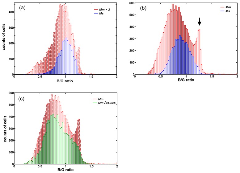
To further quantify the difference between Mm- and Ms-infected cells, we used CellProfiler to identify cells, demarcate cell boundaries and calculate the mean intensity values in both blue and green fluorescence channels. Figure 7(a) shows the typical histograms of blue/green ratio for the Mm- and Ms-infected cells at 48 h post-infection, respectively. The number of cells analyzed for each type is more than 3000. Both histograms are similar with a blue/green ratio peak at about 1 with full width at half maximum (FWHM) about 0.35. The histogram of the Mm-infected cells at 96 h post-infection (Fig. 7(b)) showed an extra peak (black arrow) at higher blue/green fluorescence intensity level (~1.25) other than the main peak (~0.85), indicating FRET process was quenched, which was due to bacteria rupturing the membrane of the phagosome. The FWHM of the main peak is about 0.5. We repeatedly observed higher counts of red fluorescence patches from the Mm-infected cells than the Ms-infected cells, indicating more Mm translocated into the cytosol and replicated. Comparing the 48 h and 96 h histograms, at 96 h post-infection Mm achieved higher incidents of cytosolic translocation than that at 48 h post-infection, while Ms had no significant change. One discrepancy between the histograms at different time points is not only the main peak shifts by 0.2, but also the FWHM changes by 0.15 for both the Mm- and Ms-infected cells. This could possibly be due to the precise control of the cell culture, and variation of FRET kit labeling process, which could lead to different green fluorescence backgrounds in cells. Further investigation is needed to apply this method on quantitative time-course study. With the same cell culture and labeling processes, histograms of both the Mm and Ms-infected cells showed similar main peaks and FWHMs. At 96 h post-infection the histogram of the MmΔc10/e6-infected cells (green plot in Fig. 7(c)) is quite similar to that of the Ms-infected cells (blue plot in Fig. 7(b)). This quantitative analysis confirmed that wild-type Mm achieved cytosolic translocation, while Ms and MmΔc10/e6 did not have such capability.
Fig. 7.
Quantification of blue vs. green fluorescence intensity from cells infected with Mm, Ms and MmΔc10/e6, respectively. (a) Histograms of blue/green ratio for the Mm- and Ms-infected cells at 48 h post-infection. The histogram of the Mm-infected cells is enlarged by 2 times. Total counted Mm-infected cells are 5141, and total counted Ms-infected cells are 3498. (b) Histograms of blue/green ratio for the Mm- and Ms-infected cells at 96 h post-infection. Total counted Mm-infected cells are 17593, and total counted Ms-infected cells are 6664. (c) Histograms of blue/green ratio for the Mm- and MmΔc10/e6-infected cells at 96 h post-infection. Total counted Mm-infected cells are 17593, and total counted MmΔc10/e6-infected cells are 11294.
6. Discussion
In this study, we have demonstrated using two-photon FRET imaging microscopy to quantify cytosolic translocation of mycobacteria in macrophages. The result has shown that the pathogenic bacteria Mm, but not the non-pathogenic Ms, induced a significant loss of the FRET signal, indicating that Mm, but not Ms, translocated into the cytosol, where bacterial β–lactamase cleaved the FRET pair in CCF4. Consistent with the loss of FRET signal, the Mm-infected macrophages showed more red fluorescence (mCherry) than the Ms-infected macrophages, indicating that more Mm got access to the cytosol and replicated. We also noticed that intentional, prolonged exposure to 710 nm excitation pulses at the power level used here for imaging over 10 minutes did not cause any appreciable photobleaching to the cells. Two-photon microscopy can induce undesired damages due to highly nonlinear effects and even optical breakdown phenomena under certain conditions [18–20]. Under such circumstances, it requires careful control of experimental conditions, such as laser wavelength, power and illumination time, to avoid undesired photodamage. It is generally recognized that compared with confocal microscopy, two-photon microscopy has minimal photobleaching and photodamage due to the fact that two-photon excitation only happens within the focal point of sub-femtolitre volume and the excitation wavelength are in the near infrared region [21]. In a developmental biology study, live mammalian embryos were exposed for 24 hours under a two-photon microscope without measureable impact on embryo development. On the contrary, confocal microscopy imaging induced damage to embryos [22]. Hence, two-photon microscopy has the advantage of less photodamage over confocal microscopy on imaging live cells and animal imaging.
Precise measurement of the FRET efficiency requires detailed studies to minimize the potential problems, such as cross talks between FRET channels, and to optimize the concentrations of donor and acceptor molecules. By measuring the spectrum of each FRET channel, several groups have developed algorithms to quantify the FRET efficiency [23–25]. Fluorescence life time measurement can also provide extra information for better quantification of FRET efficiency [26]. Further FRET measurement using the developed method on various Mm mutants or Mtb mutants with deficiency in cytosolic translocation will reveal the specific molecular roles, and help to better understand host-Mtb interactions. This study has provided a novel quantitative approach for analysis of mycobacterial cytosolic translocation, which is potentially applicable to study of other bacterial pathogens in cells or in live animals.
Acknowledgment
This study was supported by College of Science Multidisciplinary Research Award Program (MRAP) at the University of Texas at El Paso to CL, JS, HO, and CX. We would like to thank Dr. Bin Cao for his help on setting up the microscope.
References and links
- 1.Dolin P. J., Raviglione M. C., Kochi A., “Global tuberculosis incidence and mortality during 1990-2000,” Bull. World Health Organ. 72(2), 213–220 (1994). [PMC free article] [PubMed] [Google Scholar]
- 2.van der Wel N., Hava D., Houben D., Fluitsma D., van Zon M., Pierson J., Brenner M., Peters P. J., “M. tuberculosis and M. leprae Translocate from the Phagolysosome to the Cytosol in Myeloid Cells,” Cell 129(7), 1287–1298 (2007). 10.1016/j.cell.2007.05.059 [DOI] [PubMed] [Google Scholar]
- 3.Simeone R., Bobard A., Lippmann J., Bitter W., Majlessi L., Brosch R., Enninga J., “Phagosomal rupture by Mycobacterium tuberculosis results in toxicity and host cell death,” PLoS Pathog. 8(2), e1002507 (2012). 10.1371/journal.ppat.1002507 [DOI] [PMC free article] [PubMed] [Google Scholar]
- 4.Houben D., Demangel C., van Ingen J., Perez J., Baldeón L., Abdallah A. M., Caleechurn L., Bottai D., van Zon M., de Punder K., van der Laan T., Kant A., Bossers-de Vries R., Willemsen P., Bitter W., van Soolingen D., Brosch R., van der Wel N., Peters P. J., “ESX-1-mediated translocation to the cytosol controls virulence of mycobacteria,” Cell. Microbiol. 14(8), 1287–1298 (2012). 10.1111/j.1462-5822.2012.01799.x [DOI] [PubMed] [Google Scholar]
- 5.Cosma C. L., Sherman D. R., Ramakrishnan L., “The Secret Lives of the Pathogenic Mycobacteria,” Annu. Rev. Microbiol. 57(1), 641–676 (2003). 10.1146/annurev.micro.57.030502.091033 [DOI] [PubMed] [Google Scholar]
- 6.Tobin D. M., Ramakrishnan L., “Comparative pathogenesis of Mycobacterium marinum and Mycobacterium tuberculosis,” Cell. Microbiol. 10(5), 1027–1039 (2008). 10.1111/j.1462-5822.2008.01133.x [DOI] [PubMed] [Google Scholar]
- 7.Ray K., Bobard A., Danckaert A., Paz-Haftel I., Clair C., Ehsani S., Tang C., Sansonetti P., Tran G. V., Enninga J., “Tracking the dynamic interplay between bacterial and host factors during pathogen-induced vacuole rupture in real time,” Cell. Microbiol. 12(4), 545–556 (2010). 10.1111/j.1462-5822.2010.01428.x [DOI] [PubMed] [Google Scholar]
- 8.Keller C., Mellouk N., Danckaert A., Simeone R., Brosch R., Enninga J., Bobard A., “Single Cell Measurements of Vacuolar Rupture Caused by Intracellular Pathogens,” J. Vis. Exp. 76(76), e50116 (2013). [DOI] [PMC free article] [PubMed] [Google Scholar]
- 9.Zlokarnik G., Negulescu P. A., Knapp T. E., Mere L., Burres N., Feng L., Whitney M., Roemer K., Tsien R. Y., “Quantitation of Transcription and Clonal Selection of Single Living Cells with β-Lactamase as Reporter,” Science 279(5347), 84–88 (1998). 10.1126/science.279.5347.84 [DOI] [PubMed] [Google Scholar]
- 10.LiveBLAzer™ FRET — B/G Loading Kit with CCF2-AM and CCF4-AM,” http://www.lifetechnologies.com/order/catalog/product/K1029?CID=AFLBC-425-Discovery-Sciences-K1029.
- 11.Zipfel W. R., Williams R. M., Webb W. W., “Nonlinear magic: multiphoton microscopy in the biosciences,” Nat. Biotechnol. 21(11), 1369–1377 (2003). 10.1038/nbt899 [DOI] [PubMed] [Google Scholar]
- 12.Elangovan M., Wallrabe H., Chen Y., Day R. N., Barroso M., Periasamy A., “Characterization of one- and two-photon excitation fluorescence resonance energy transfer microscopy,” Methods 29(1), 58–73 (2003). 10.1016/S1046-2023(02)00283-9 [DOI] [PubMed] [Google Scholar]
- 13.Wallrabe H., Stanley M., Periasamy A., Barroso M., “One- and two-photon fluorescence resonance energy transfer microscopy to establish a clustered distribution of receptor-ligand complexes in endocytic membranes,” J. Biomed. Opt. 8(3), 339–346 (2003). 10.1117/1.1584444 [DOI] [PubMed] [Google Scholar]
- 14.Li C., Pastila R. K., Pitsillides C., Runnels J. M., Puoris’haag M., Côté D., Lin C. P., “Imaging leukocyte trafficking in vivo with two-photon-excited endogenous tryptophan fluorescence,” Opt. Express 18(2), 988–999 (2010), http://www.opticsinfobase.org/oe/abstract.cfm?uri=oe-18-2-988. 10.1364/OE.18.000988 [DOI] [PMC free article] [PubMed] [Google Scholar]
- 15.http://www.cellprofiler.org.
- 16.Otsu N., “A threshold selection method from gay-level histograms,” IEEE Trans. Systems, Man, and Cybernetics 9(1), 62–66 (1979). 10.1109/TSMC.1979.4310076 [DOI] [Google Scholar]
- 17.Gao L.-Y., Guo S., McLaughlin B., Morisaki H., Engel J. N., Brown E. J., “A mycobacterial virulence gene cluster extending RD1 is required for cytolysis, bacterial spreading and ESAT-6 secretion,” Mol. Microbiol. 53(6), 1677–1693 (2004). 10.1111/j.1365-2958.2004.04261.x [DOI] [PubMed] [Google Scholar]
- 18.Patterson G. H., Piston D. W., “Photobleaching in Two-Photon Excitation Microscopy,” Biophys. J. 78(4), 2159–2162 (2000). 10.1016/S0006-3495(00)76762-2 [DOI] [PMC free article] [PubMed] [Google Scholar]
- 19.Hopt A., Neher E., “Highly Nonlinear Photodamage in Two-Photon Fluorescence Microscopy,” Biophys. J. 80(4), 2029–2036 (2001). 10.1016/S0006-3495(01)76173-5 [DOI] [PMC free article] [PubMed] [Google Scholar]
- 20.Nichols M. G., Barth E. E., Nichols J. A., “Reduction in DNA Synthesis During Two-photon Microscopy of Intrinsic Reduced Nicotinamide Adenine Dinucleotide Fluorescence,” Photochem. Photobiol. 81(2), 259–269 (2005). 10.1562/2004-08-05-RA-263.1 [DOI] [PubMed] [Google Scholar]
- 21.König K., “Cell Damage During Multi-Photon Microscopy”, in Handbook of Biological Confocal Microscopy, 3rd ed., Pawley J.B., Editor, Springer: New York: 680–689 (2006). [Google Scholar]
- 22.Squirrell J. M., Wokosin D. L., White J. G., Bavister B. D., “Long-term two-photon fluorescence imaging of mammalian embryos without compromising viability,” Nat. Biotechnol. 17(8), 763–767 (1999). 10.1038/11698 [DOI] [PMC free article] [PubMed] [Google Scholar]
- 23.Gordon G. W., Berry G., Liang X. H., Levine B., Herman B., “Quantitative fluorescence resonance energy transfer measurements using fluorescence microscopy,” Biophys. J. 74(5), 2702–2713 (1998). 10.1016/S0006-3495(98)77976-7 [DOI] [PMC free article] [PubMed] [Google Scholar]
- 24.Xia Z., Liu Y., “Reliable and global measurement of fluorescence resonance energy transfer using fluorescence microscopes,” Biophys. J. 81(4), 2395–2402 (2001). 10.1016/S0006-3495(01)75886-9 [DOI] [PMC free article] [PubMed] [Google Scholar]
- 25.Berney C., Danuser G., “FRET or no FRET: a quantitative comparison,” Biophys. J. 84(6), 3992–4010 (2003). 10.1016/S0006-3495(03)75126-1 [DOI] [PMC free article] [PubMed] [Google Scholar]
- 26.Zeug A., Woehler A., Neher E., Ponimaskin E. G., “Quantitative intensity-based FRET approaches-a comparative snapshot,” Biophys. J. 103(9), 1821–1827 (2012). 10.1016/j.bpj.2012.09.031 [DOI] [PMC free article] [PubMed] [Google Scholar]


