Abstract
• Background and Aims The xylem, or water transport system, in vascular plants adopts different morphologies that appear sequentially during growth phases. This paper proposes an explanation of these morphologies based on engineering design principles.
• Methods Using microscopic observations of the different growth stages, an engineering analysis of the xylem vessels as a closed cylinder under internal pressure is carried out adopting pressure vessel design concepts.
• Key Results The analysis suggests that the xylem vessel structural morphology follows the ‘constant strength’ design principle, i.e. all of the material within the wall of the xylem is loaded equally to its maximum allowable stress capacity, and the amount of material used is therefore systematically minimized. The analysis shows that the different structural designs of the xylem vessel walls (annular, helical, reticulate and pitted) all quantitatively follow the constant strength design principle.
• Conclusions The results are discussed with respect to growth and differentiation. It is concluded that the morphology of the xylem vessel through the different phases of growth seems to follow optimal engineering design principles.
Keywords: Xylem vessel, vascular plant, constant strength, structural design, xylem cell wall, biomechanics
INTRODUCTION
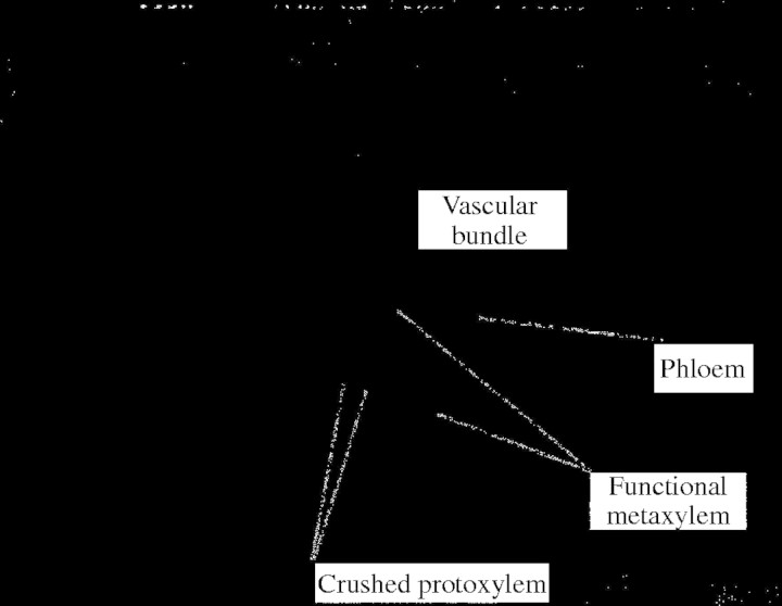
The xylem is the principal water conducting tissue in a vascular plant. It is divided between primary and secondary xylem. Primary xylem consists of an early part, the protoxylem, which differentiates and matures among actively elongating plant organs, and a later part, the metaxylem, which initiates during the growth of the primary body of the plant but matures after elongation has ceased. Secondary xylem forms during secondary growth stages and initiates after all elongation has been completed. Cell walls in the tracheary elements of the xylem have a variety of secondary wall thickenings. Different types appear in an ontogenetic sequence with annular thickening occurring first, followed in order by helical, scalariform, reticulate and pitted thickening. Occurrence of the secondary wall types depends on the growth and maturity of the tracheary element and cannot be assigned distinctly to any one type of xylem. Two types of tracheary elements can be distinguished: tracheids and vessel elements. Tracheids appear mainly in woody plants and are connected laterally through multiple pits. Vessels appear in both woody and non-woody plants and are built of numerous vessel members joined at their ends. They are typically found in vascular bundles inside different plant organs (Fig. 1).
Fig. 1.
Micrograph of vascular bundle in a grass stem showing large open vessels (metaxylem), early formed collapsed vessels (protoxylem) and phloem.
In this study, the biomechanics of vessel elements are analysed from an engineering point of view. An engineering model is derived by assuming that the design of the wall thickening follows a constant strength design principle, which, by loading all parts to their maximum allowable stress capacity, minimizes the amount of material used. The quantitative and qualitative predictions of this engineering model are compared with the structural designs of plant xylem vessel cell walls as reported in the published literature and as observed on some herbaceous and non-woody vascular plants to provide a new functional explanation for the different observed types of secondary wall thickening: annular, helical, reticulate and pitted.
BIOMECHANICS OF THE VESSEL ELEMENTS
From an engineering point of view, the xylem is the water distribution network that transmits water from the root collection system to the main consumers, the leaves, in the upper parts of the plant. Transpiration of the leaf mesophyll cells causes a water potential difference between the leaf and the xylem, resulting in water transport. During the growing season the water is lifted up to the leaves by negative pressures, less than atmospheric, created by transpiration. Vessels, made of elongated hollow cells connected end to end (Zimmerman, 1983), are subjected to high internal negative pressures (Choat et al., 2003) that must be resisted by their walls to prevent cell collapse. Microscopic investigation shows that primary vessel walls are reinforced by the secondary wall, a lignified cell-wall thickening, deposited on the inside of the primary wall of the cell (Wooding and Northcote, 1964; Bierhorst and Zamora, 1965; Ray, 1972; Neushul, 1974) (Fig. 2). Secondary wall first appears as an annular thickening. Subsequently, the thickening becomes helical, followed by interconnected helices, coils or scalariform thickening. The final structure, encountered in the last ontogenetic stage, has reticulate or net-like thickening, or uniform thickening with staggered pits in pitted vessels (Fig. 2) (Bierhorst and Zamora, 1965; Jensen and Salisbury, 1972; Ray, 1972; Neushul, 1974; Esau, 1977; Fahn, 1990). The type of secondary wall thickening is determined by the dimension (diameter) of the vessel and the maturity and growth stage of the plant (ontogeny). The literature contains many descriptions and discussions of the secondary wall patterns without an exact analysis or explanatory model. The mechanical engineering design problem of the xylem vessel element is treated in the next section to provide a possible explanation for these observations.
Fig. 2.
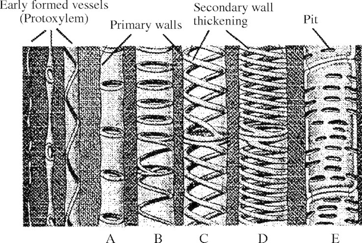
Types of vessel elements with different secondary wall thicknening patterns. (A) Annular; (B) annular/helical; (C) double helical opposite curl; (D) double helical same curl; and (E) pitted (after Ray, 1972; permission requested from Holt, Reinhart and Winston Inc.).
In addition to mechanically resisting the water pressure, the xylem also has to satisfy other design constraints such as plant growth strains, hydraulic conductivity and connectivity between adjacent cells. These will not be considered in the derivation of the engineering model.
ENGINEERING MODEL
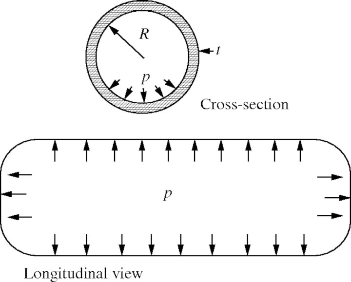
The vessel element is analysed as a closed-end cylinder, of uniform radius, R, and wall thickness, t, subjected to an internal pressure, p, which can be either negative or positive; engineers call such a structure a ‘pressure vessel’ (Fig. 3).
Fig. 3.
Xylem vessel modelled as a pressurized tube (see text for detail).
The primary cell wall is a layer made of randomly orientated cellulose microfibrils in a relatively visco-elastic matrix that allows extension and elongation (Bodig and Jane, 1982; Niklas, 1992). Some re-orientation of the microfibrils is thought to take place under elongation stresses during growth. There is evidence that microfibrils get deposited mostly along the transverse or hoop direction before some get realigned along the fibre axis (Niklas, 1992) due to elongation stresses. For the purposes of the analysis the primary wall is considered to be homogeneous and isotropic with a maximum allowable stress of σ* both axially and transversely.
The secondary wall layer of xylem tracheids is known to consist of highly orientated cellulose microfibrils with a structure stabilized by lignin (Mark, 1967; Bodig and Jane, 1982; Niklas, 1992; Reiterer et al., 1999). The secondary wall of tracheids contributes over 80 % of the cell wall thickness and provides mechanical support to the plant. The same structure of highly orientated cellulose microfibrils is usually assumed for the secondary wall layer of xylem vessels in woody and non-woody plants, albeit the structural support function to the plant is not required. The cellulose microfibrils in the secondary wall of vessels are expected to be more-or-less aligned along the direction of deposition (annular, helical, etc.) with varying amounts of lignin deposited along the microfibrils. These factors result in differing strengths between the primary and secondary layers. In order to allow for this possible difference, a strength ratio, r, is introduced where the maximum allowable stress of the secondary wall layer along the direction of its deposition would be rσ*. The secondary wall layer, which is deposited along circular, spiral or net-like patterns, acts as a unidirectional reinforcement and hence only its axial properties are relevant to the analysis. The anisotropy of the secondary wall does not affect the model. It is worthwhile noting that the strength ratio, r, could be derived from basic composite theory as r = Esw/Epw; where Esw is the modulus of elasticity of the secondary wall, and Epw is the modulus of elasticity of the primary wall, when both walls are subjected to the same strains. The use of this strength ratio would account in the most general way for the difference in properties between the primary and secondary walls. When r = 1, the secondary and primary walls are assumed to have the same maximum allowable stress.
To minimize the total amount of material used, a fully stressed design is sought, i.e. all parts of the xylem are assumed to be equally stressed in all directions. The internal pressure causes hoop and longitudinal stresses, with the hoop stresses being twice the longitudinal. The forces per unit length in the hoop and longitudinal directions, Fh and F1, respectively, that the tube has to resist can be written as:
 |
 |
Note that a positive pressure (cell pressure greater than atmospheric) leads to tensile stresses in the wall while a negative pressure (cell pressure less than atmospheric) leads to compressive stresses. If the maximum allowable stress in the primary wall material is σ*, then the available resisting hoop force per unit length will be σ*t. Depending on the relative magnitudes of the pressure, the allowable stress in the wall material and the geometry of the tube, three cases will be encountered, each of which is analysed below.
Case I. σ*t ≥ pR, which implies that the tube can readily resist the hoop and longitudinal stresses caused by the internal pressure.
Case II.pR > σ*t ≥ pR/2, which implies that the longitudinal stresses can be resisted by the primary wall material but that reinforcement is needed along the hoop direction. If the reinforcement is to be provided by deposition of a thickening of some material with an allowable stress of rσ*, then the simplest form of hoop reinforcement is rings of secondary wall material with a cross-section A and a centre-to-centre spacing s. The material in the rings acts in uniaxial tension or compression similar to a reinforcing strap or tie (similar to metallic straps around a wooden barrel). By comparing the forces in the hoop direction, A/s has to satisfy:
 |
Equation 2 can be readily solved as an equality for the minimum A/s and an appropriate reinforcement can be designed.
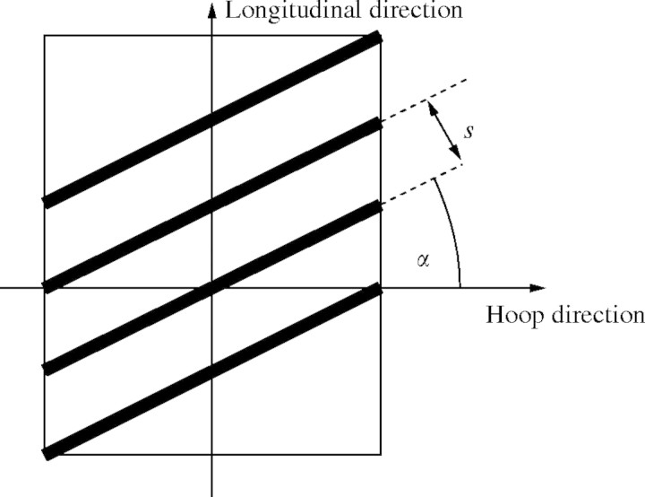
Case III. σ*t < pR/2, which implies that the tube wall needs reinforcing in the longitudinal as well as the hoop direction to resist internal pressures. The reinforcement can then be in the form of a helical-coil thickening of secondary wall material with an allowable stress of rσ* at an angle α to the diametral plane, with cross-section A, and a spacing s, as shown in Fig. 4. A simple ‘netting analysis’ (Rolston, 1990) can be performed to estimate the strength now available to resist the applied longitudinal and hoop stresses. The optimal design is assumed to be that which allows the stresses along the helical reinforcement and those perpendicular to it to reach their maximum allowable values simultaneously. Equating the resisting forces to the applied ones in the hoop and longitudinal directions, respectively, the following system of equations is obtained:
 |
 |
Fig. 4.
Secondary wall thickening modelled as helical winding (case III; see text for detail).
For a given radius, thickness, pressure and allowable stresses in the primary and secondary wall materials, there exists an optimal reinforcement orientation α that is independent of A/s, found by combining eqns (3a) and (3b):
 |
Note that if the contribution of the primary wall, σ*t, is neglected eqn (4) yields α = 35·26°, which is the optimal winding angle in fibre-reinforced pressure vessels, a result well known to composites engineers and designers of ‘pressure vessels’ (Harvey, 1980; Rolston, 1990). In all other cases where the primary wall contributes some mechanical resistance, α, the inclination angle of the reinforcement thickening will always be less than 35·26°. A/s, the reinforcement ratio, is found to be:
 |
Finally, if the reinforcement is positioned optimally to provide maximum reinforcement with the least amount of material, it satisfies the following geometric relationship independent of p, R and σ*:
 |
Note that eqns (3)–(6) are identical for α and −α, which means that the reinforcement is equally effective whether the winding is from left to right or right to left; for a helix this translates into positive or negative curl (by the right hand rule).
In the discussion of cases I to III, only the normal (compressive or tensile) stresses caused by the internal pressure were considered and compared to the available resistance of the xylem wall. In addition to biaxial stretching or compression, the hoop and longitudinal loads result in shear forces acting along inclined planes in the wall material. The shear force per unit length along an arbitrary plane inclined at an angle θ to the diametral plane Sθ is given by:
 |
Assuming an isotropic primary wall material of uniform thickness, the available resistance to shear is σ*t/2. For all possible values of θ, sinθ cosθ ≤ 0·5, hence for cases I and II the available wall resistance exceeds the maximum applied shear stresses. For case III with σ*t < pR/2, an inclined thickening reinforcement is provided to resist hoop and longitudinal forces. In its simplest form, a single helix of angle α, the reinforcement does not contribute to the shear resistance of the tube wall on a plane inclined at α. A minimum wall thickness is then required to resist these shear forces and it can be found by comparing the applied force and the available resistance:
 |
When reinforcing helices of opposite curls are provided then the added area of the reinforcement also resists shears and the available shear resistance increases with the reinforcement ratio. Inequality (8) can be rewritten to give the limiting wall thickness before a double helix with opposite curls is required.
The above analysis is based on the ‘constant strength’ design principle (Flugge, 1966): the optimum design is that which stresses all material to the maximum allowable stress. Xylem vessels formed during growth and elongation of the plant, the protoxylem, are subjected to high longitudinal tensile stresses (Paolillo and Rubin, 1991; Niklas, 1992) in addition to the negative internal pressure: they fail by rupture of the primary wall and collapse under excessive elongation and internal pressure (Figs 1 and 2). The primary xylem vessels that mature after elongation ceases, the metaxylem, are subject only to internal pressure: negative in the normal situation of leaf transpiration and upward ‘pulling’ of water, and positive during the rare occasions of suppressed transpiration or very high humidity (Zimmerman, 1983). Failure can occur either by cell wall yielding or buckling: cell wall yield refers to material failure while buckling refers to a geometric instability failure (for instance, a light plastic ruler bowing out of shape when compressed at its ends or a bent straw kinking on the compressive face). Yielding of the vessel cell wall can occur under the combination of tensile (positive pressure) or compressive (negative pressure) hoop and longitudinal stresses. Buckling can occur under the combined effect of the hoop and longitudinal compressive stresses due to positive pressure; this type of failure is similar to that of a closed-end cylindrical shell under external hydrostatic pressure.
To determine if yielding or buckling is the dominant mode of failure, we can model a vessel element with an un-reinforced primary wall as a cylindrical shell under hydrostatic pressure of length L, radius R, uniform wall thickness t, and isotropic homogeneous properties (modulus of elasticity E, yield strength σy and Poisson's ratio of 0·3). For cylinders with L/√Rt > 4, the critical hydrostatic pressure, Pcr, can be found from Batdorf's approximate formula (Kollàr and Dulàcska, 1984) as:
 |
The pressure, py, at which yielding of the cylinder wall takes place can be found by using the von Mises yielding criterion (Illston et al., 1979):
 |
where the principal stresses are given by:
 |
 |
Combining eqns (10) and (11), the yielding pressure, py, is obtained as:
 |
The relative importance of yielding over buckling can be estimated by taking the ratio of py to pcr:
 |
if the ratio is smaller than 1, yielding precedes buckling and vice versa. Hence the mode of failure of the vessel cell wall is a function of the material and geometric properties of the vessel element. Table 1 presents some numerical data for these properties accumulated from the sketchy information available in the literature. Table 2 contains cross-sectional properties obtained from specific measurements on micrographs of vessel elements from non-woody plants. An element from Table 2 of typical dimensions would have R/t = 10 and L/R in the range of 15–100; its cell wall properties can be estimated as E = 5 GPa and σy = 5 MPa, giving σy/E = 0·001.
Table 1.
Vessel element dimensions and cell wall properties
| Plant type |
Wall thickness, t (μm) |
Radius, R (μm) |
Length, L (mm) |
Modulus of elasticity, E (GPa) |
Yield strength, σy (MPa) |
Source of data |
|---|---|---|---|---|---|---|
| Lily stem (Lilium) | 0·5–1·0 | 15–25 | 0·5–1·0 | –a | – | SEMb investigation |
| Monocotyledons | – | – | 0·76–3·96 | – | – | Cheadle (1943) |
| Plant stems and roots | – | – | – | 2·8–7·0 | 50–120 (tensile) 6–11 (shear) | Blahovec (1988) |
| Iris leaf | – | – | – | 2·7–7·1 | – | Gibson et al. (1988) |
| Hardwoods | – | 20–350 | 0·2–1·3 | – | – | Bodig and Jayne (1982) |
| Wood | – | – | – | 35 | 120 | Gibson and Ashby (1988) |
| Oak latewood (Quercus rubra) | 1–6 | 30–100 | 0·2–0·4 | – | – | Gibson and Ashby (1988), Siau (1984) |
–, information not available;
scanning electron microsope.
Table 2.
Dimensions and geometry of annular and helically reinforced xylem vessels in non-woody plants
| Source of data |
Wall thickness, t (μm) |
Thickening spacing, s (μm) |
Thickening area, A (μm2) |
Estimated angle, α (degrees) |
Radius of vessel, R (μm) |
|---|---|---|---|---|---|
| Esau 1977, fig. 8.10a | 0·38 | 1·82 | 0·87 | 10–20 | 3·60 |
| Esau 1977, fig. 8.12a | 0·38 | 3·50 | 1·56 | 10–17 | 4·25 |
| Jensen and Salisbury, 1972, p.409 | 0·5 | 6·0 | 4·22 | 12–17 | 5·0 |
| Roberts, 1976, fig. 27 | 0·5 | 1·81 | 0·91 | 0–3 | 6·88 |
| SEMa investigation (Lilium) | 0·54 | 5·36 | 3·06 | 9 | 15·71 |
| SEMa investigation (Lilium) | 0·91 | 6·97 | 3·24 | 0 | 7·88 |
Scanning electron microscope.
Using these typical numbers in eqn (13) the ration py/pcr varies from 0·6 to 4·0; we expect yielding to dominate in some cases while buckling would dominate in others similarly to the behaviour of tubular structures encountered in nature (Karam and Gibson, 1994). The clarification of this issue requires detailed experimental measurements on specific samples, and falls beyond the scope of this work. In the rest of this paper it will be assumed that the main purpose of the secondary wall reinforcement thickening is to prevent yielding of the walls.
DISCUSSION
Geometry of secondary wall thickening
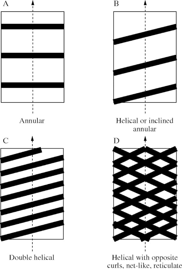
The botanical literature gives a wide range of descriptions of secondary wall thickening patterns in xylem vessels (Goodwin, 1942; Wooding and Northcote, 1964; Jensen and Salisbury, 1972; Ray, 1972; Neushul, 1974; Esau, 1977; Fahn, 1990). Here those descriptions are compared with the geometries suggested by the engineering model developed in the previous section. It is noted that the optimum design from the structural perspective must also ensure the cell opening is large enough to maintain hydraulic efficiency, allowing the flow of fluid between cells. For case II where only hoop reinforcement is needed, the optimal geometry of the secondary wall is given by equally spaced rings or annuli as determined from eqn (2). For case III when only a little reinforcement is needed, i.e. A/s as determined from eqn (5) is small, inclined rings or a helical thickening will do. If more reinforcement is required, a second helix with the same curl can be added with the condition that s, the spacing, has to be larger than the thickness of the helix, so that helices do not merge. If the shear resistance of the xylem wall is exceeded, as well as its hoop and longitudinal resistance, then the addition of a second helix of opposite curl will be required. As the pressure or the radius increase, eqn (5) calls for larger reinforcement ratios, A/s. Noting that the addition of similar-curl helices to other closely spaced helices will result in a total material bridging and a less-than-optimal uniform secondary wall thickening, or no added shear resistance for example, the only possible solution is to add helices with an opposite curl, resulting in a net-like or reticulate pattern. This can be attained by simply bridging the spires of the already present helices. The different reinforcement design patterns are show in Fig. 5. All the secondary wall patterns reported in the literature (Fig. 2) correspond to a design solution from Fig. 5. or to a combination of two solutions.
Fig. 5.
Different thickening patterns obtained from helical winding combinations. (A) Annular thickening; (B) single helix; (C) double helices; and (D) reticulated pattern (opposite curl helices).
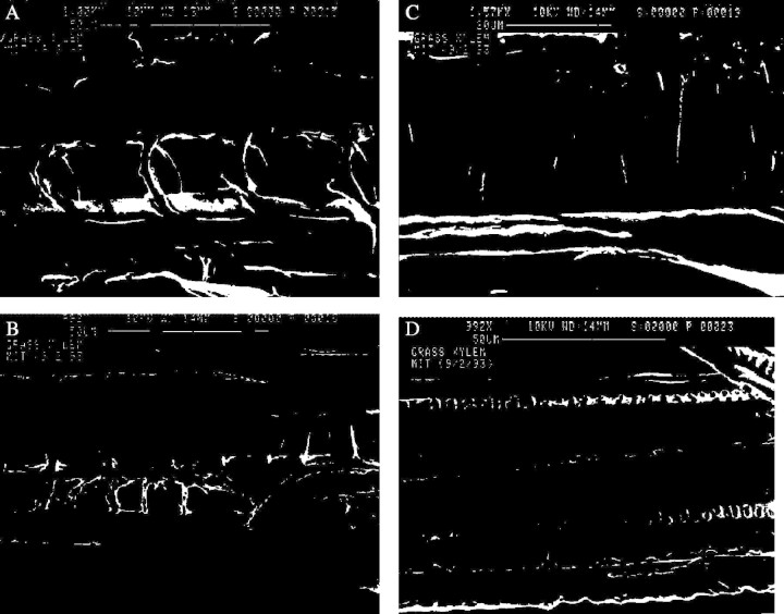
Figure 6 shows scanning electron micrographs of the xylem of a grass stem (Elytrigia repens) where different secondary wall thickening patterns can be seen to agree qualitatively with the predictions of the model (Fig. 5). A complete set of optical photomicrographs was presented by Goodwin (1942) in his seminal work, showing all the different types of secondary wall thickening. Bierhorst and Zamora (1965) described secondary wall pattern formation and compiled observations on more than 1350 species; Meylan and Butterfield (1972) also presented scanning electron micrographs of wood xylem vessel elements, showing with exceptional detail the net-like or reticulate pattern of the secondary wall similar to Fig. 5D. Classical botany texts and publications contain a wealth of such micrographs that can be seen to follow the optimal design solutions. Note that the pitted vessel type reported in many works as the last form of reinforced xylem (Jensen and Salisbury, 1972; Ray, 1972; Neushul, 1974; Esau, 1977) (Figs 2E and 6D) corresponds to a heavily thickened reticulate pattern (Fig. 5D), where the secondary wall approaches a uniform thickening layer. The regularly staggered pits correspond to unthickened parts of the xylem with the primary wall autolysed to allow side-to-side transmission of water from one vessel to the other or to the surrounding parenchyma. Figure 7 shows schematically the evolution from the reticulate to the pitted pattern.
Fig. 6.
Micrographs of thickening patterns in xylem of Elytrigia repens. (A) Annular thickening; (B) single helix; (C) double helices; and (D) pitted pattern.
Fig. 7.
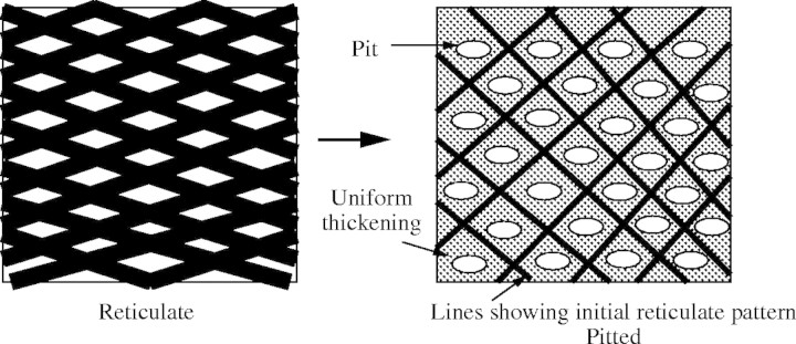
Sketch showing transition from reticulate to pitted pattern.
Theoretical predictions and experimental observations
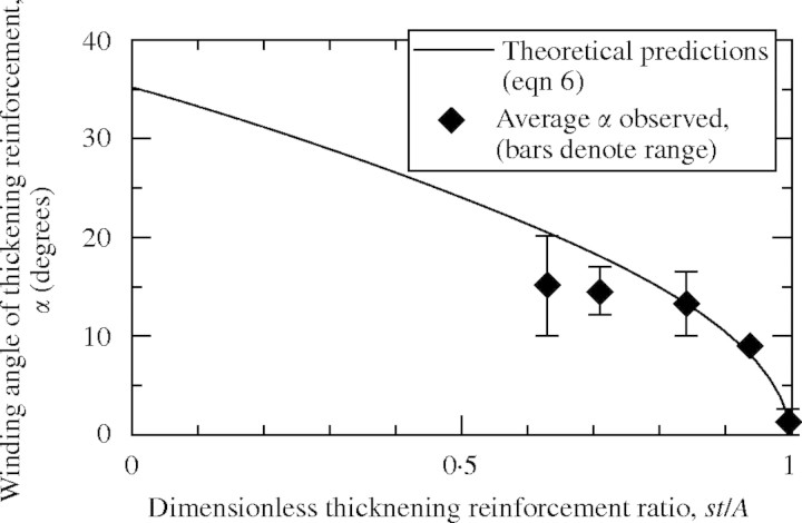
In a given plant species it is reasonable to assume that the primary cell walls of vessels would have more or less the same average thickness, t, as well as the same average wall stress, σ*, across the existing range of diameters and lengths. Using this assumption eqn (5) suggests the need for larger reinforcement ratios, A/s, as the radius, R, or the pressure, p, increase in the xylem vessel. This prediction is verified by the observations of Goodwin (1942) and Esau (1977) who show a progression of thickening patterns, from annular to reticulate, as the radius of the vessel increases and the primary wall thickness remains more or less constant. Equation (6) provides a direct way of verifying the mechanical model against geometric measurements. t, s, A and α were estimated from scanning electron microscope observations performed in this study and from published photomicrographs of vessel sections in mostly herbaceous plants (Table 2). The dimensionless factor st/rA was then calculated and compared with theoretical predictions of eqn (6) in Fig. 8 for r = 1; the data points show the same trend as predicted by eqn (6) and agreement is relatively good. Note that the last entry in Table 2 does not show in Fig. 8 because it falls under case II where only hoop reinforcement is needed in the form of circumferential rings: the observed angle is zero as predicted by the model, st/A > 1 and eqn (6) is not applicable.
Fig. 8.
Helical thickening winding angle plotted against dimensionless reinforcement ratio (eqn 6).
Growth, differentiation and secondary wall thickening
The secondary wall thickening pattern has been used as an index of growth and differentiation in xylem vessels (Goodwin, 1942; Wooding and Northcote, 1964; Bierhorst and Zamora, 1965; Jensen and Salisbury, 1972; Ray, 1972; Neushul, 1974; Esau, 1977; Zimmerman, 1983; Fahn, 1990; Paolillo and Rubin, 1991). The protoxylem develops and matures with the growing plant and has a smaller diameter than the metaxylem, which matures after the plant has finished its primary growth phase (Fig. 1). Having a smaller diameter, the protoxylem only needs annular and helical reinforcement while the metaxylem, functioning at the same pressure but with a larger diameter, will require more reinforcement resulting in a reticulate pattern. Putting aside hydraulic considerations, one reason why the plant only develops small diameter xylem (protoxylem) in its early growth phase is the need to allow for growing strains, which can reach as high as 13 % in a functional xylem, before the primary cell wall is ruptured and the vessel in question is rendered useless (Paolillo and Rubin, 1991; Niklas, 1992) (Figs 1 and 2). The annular and helical reinforcement patterns do not offer as much resistance to elongation as a reticulate pattern. The helical and annular reinforcement, having the lowest longitudinal stiffness among secondary wall patterns, will resist growth the least and stay functional for the longest time possible.
Concluding remarks
The constant strength design principle has been used by mechanical engineers to optimize the design of engineering pressure vessels (Harvey, 1980). Application of this principle has led to metallic pressure vessels reinforced with coil-layer, ribbon or wire-wrapping and helical corrugations, and to fibre-reinforced plastic pressure vessels manufactured with optimized helical winding patterns (Harvey, 1980; Rolston, 1990; Shevchenko et al., 1993; Contech, 1994). Here, a simple mechanical model of the xylem vessel as a pressure vessel has been utilized to show that the constant strength principle can be used to explain secondary wall thickening patterns in cell walls. Experimental observations of the geometry and relative dimensions of the reinforcement thickening agree well with the predictions of the model. Mechanical design considerations underlie many observed characteristics of the xylem vessels and tracheids, which are best described as composite hierarchical systems. Recent experimental results by Reiterer et al. (1999) and Choat et al. (2003) point to the existence of optimal orientation angles of microfibrils in the secondary wall. A modelling approach based on optimization principles similar to the one presented above for secondary cell wall deposition patterns could be used to analyse and understand these microstructural systems as well (Gibson et al., 1995).
Acknowledgments
The author acknowledges the financial support of US NSF (grants number MSS-9202202 and EID 9023692) for part of this work and the invaluable contribution of Professor Lorna Gibson of the Materials Science and Engineering Department at MIT.
LITERATURE CITED
- Bierhorst DW, Zamora PM. 1965. Primary xylem elements and element associations of angiosperms. American Journal of Botany 52: 657–710 [Google Scholar]
- Blahovec J. 1988. Mechanical properties of some plant materials. Journal of Materials Science 23: 3588–3593. [Google Scholar]
- Bodig J, Jayne BA. 1982.Mechanics of wood and wood composites. New York: Van Nostrand Reinhole Co. [Google Scholar]
- Cheadle VI. 1943. The origin and certain trends of specialization of the vessel in the monocotyledon. American Journal of Botany 30: 11–17. [Google Scholar]
- Choat B, Ball M, Luly J, Holtum J. 2003. Pit membrane porosity and water stress-induced cavitation in four co-existing dry rainforest tree species. Plant Physiology 131: 41–48. [DOI] [PMC free article] [PubMed] [Google Scholar]
- Contech Construction Products Inc. 1994.Ultra Flo storm Sewer pipe, UF-101, ed.5. Middletown, Ohio. [Google Scholar]
- Esau K. 1977.Anatomy of seed plants, 2nd ed. New York: John Wiley and Sons. [Google Scholar]
- Fahn A. 1990.Plant anatomy, 4th ed. Oxford: Pergamon Press. [Google Scholar]
- Flugge W. 1966.Stresses in shells. New York: Springer-Verlag. [Google Scholar]
- Gibson LJ, Ashby MF. 1988.Cellular solids. Oxford: Pergamon Press. [Google Scholar]
- Gibson LJ, Ashby MF, Easterling KE. 1988. Structure and mechanics of the iris leaf. Journal of Materials Science 23: 3041–3048. [Google Scholar]
- Gibson LJ, Ashby MF, Karam GN, Wegst U, Shercliff HR. 1995. The mechanical properties of natural materials. II. Microstructures for mechanical efficiency Proceedings of the Royal Society of London Series A 450: 141–162. [Google Scholar]
- Goodwin RH. 1942. On the development of xylary elements in the first internode of Avena in dark and light. American Journal of Botany 29: 818–828. [Google Scholar]
- Harvey JF 1980.Pressure component construction. New York: Van Nostrand Reinhold Co. [Google Scholar]
- Illston JM, Dinwoodie JM, Smith AA. 1979.Concrete, timber and metals. New York: Van Nostrand Reinhold International. [Google Scholar]
- Jensen WA, Salisbury FB. 1972.Botany: an ecological approach. Belmont, CA: Wadsworth Publishing Co. Inc. [Google Scholar]
- Karam GN, Gibson LJ. 1994. Biomimicking of animal quills and plant stems: natural cylindrical shells with foam cores. Materials Science and Engineering C Biomimetic Materials, Sensors and Systems C2: 113–132. [Google Scholar]
- Kollàr L, Dulàcska E. 1984.Buckling of shells for engineers. New York: John Wiley and Sons. [Google Scholar]
- Mark RE. 1967.Cell wall mechanics of tracheids, Yale University Press. [Google Scholar]
- Meylan BA, Butterfield BG. 1972. Perforation plate development in Knightia excelsa R. Br: a scanning electron microscope study. Australian Journal of Botany 20: 79–86. [Google Scholar]
- Neushul M. 1974.Botany. Santa Barbara, CA: Hamilton Pub. Co. [Google Scholar]
- Niklas KJ. 1992.Plant biomechanics. Chicago IL: The University of Chicago Press. [Google Scholar]
- Paolillo Jr DJ, Rubin G. 1991. Relative elemental rates of elongation and the protoxylem-metaxylem transition in hypocotyls of soybean seedlings. American Journal of Botany 78: 845–854. [Google Scholar]
- Ray PM. 1972.The living plant. New York: Holt, Rinehart and Winston Inc. [Google Scholar]
- Reiterer A, Lichtenegger H, Tschegg S, Fratzl P. 1999. Experimental evidence for a mechanical function of the cellulose microfibril angle in wood cell walls. Philosophical Magazine A 79: 2173–2184. [Google Scholar]
- Roberts LW. 1976.Cytodifferentiation in plants. Cambridge: Cambridge University Press. [Google Scholar]
- Rolston JA. 1990.Filament winding In: Bader M, Smith W, Isham A, Rolston JA, Metzner A, eds. Processing and fabrication technology. Delaware composites design encyclopedia 3. Lancaster, PA: Technomic Pub. Co. Inc., 193–204. [Google Scholar]
- Shevchenko YuN, Merzlyakov VA, Galishin AZ, Novikov SV, Los AO, Yukhimets PS. 1993. Determination of the limiting stress-strain state of helically corrugated pipes. Problemy Prochnosti 7: 48–53 (English translation 507–511). [Google Scholar]
- Siau JF. 1984.Transport processes in wood. Berlin: Springer-Verlag. [Google Scholar]
- Wooding FBP, Northcote DH. 1964. The development of the secondary wall of the xylem in Acer pseudoplatanus Journal of Cell Biology 23: 327–337. [DOI] [PMC free article] [PubMed] [Google Scholar]
- Zimmerman MH. 1983.Xylem structure and the ascent of sap. Berlin, Heidelberg: Springer-Verlag. [Google Scholar]


