Abstract
Purpose:
Side readout of scintillation light from crystal elements in positron emission tomography (PET) is an alternative to conventional end-readout configurations, with the benefit of being able to provide accurate depth-of-interaction (DOI) information and good energy resolution while achieving excellent timing resolution required for time-of-flight PET. This paper explores different readout geometries of scintillation crystal elements with the goal of achieving a detector that simultaneously achieves excellent timing resolution, energy resolution, spatial resolution, and photon sensitivity.
Methods:
The performance of discrete LYSO scintillation elements of different lengths read out from the end/side with digital silicon photomultipliers (dSiPMs) has been assessed.
Results:
Compared to 3 × 3 × 20 mm3 LYSO crystals read out from their ends with a coincidence resolving time (CRT) of 162 ± 6 ps FWHM and saturated energy spectra, a side-readout configuration achieved an excellent CRT of 144 ± 2 ps FWHM after correcting for timing skews within the dSiPM and an energy resolution of 11.8% ± 0.2% without requiring energy saturation correction. Using a maximum likelihood estimation method on individual dSiPM pixel response that corresponds to different 511 keV photon interaction positions, the DOI resolution of this 3 × 3 × 20 mm3 crystal side-readout configuration was computed to be 0.8 mm FWHM with negligible artifacts at the crystal ends. On the other hand, with smaller 3 × 3 × 5 mm3 LYSO crystals that can also be tiled/stacked to provide DOI information, a timing resolution of 134 ± 6 ps was attained but produced highly saturated energy spectra.
Conclusions:
The energy, timing, and DOI resolution information extracted from the side of long scintillation crystal elements coupled to dSiPM have been acquired for the first time. The authors conclude in this proof of concept study that such detector configuration has the potential to enable outstanding detector performance in terms of timing, energy, and DOI resolution.
Keywords: positron emission tomography (PET), depth-of-interaction (DOI), time-of-flight (TOF), side readout
1. INTRODUCTION
The performance of a positron emission tomography (PET) detector can be characterized by its (1) spatial resolution, (2) energy resolution, (3) timing resolution, and (4) photon sensitivity.1 That is, the following characteristics are desired in PET detectors to produce high quality images: fine spatial resolution (in 3D) to pinpoint the annihilation photon interactions coming from the distribution of radiotracers; a high energy resolution to accurately distinguish true coincidence events from scattered events; excellent timing resolution to reduce random coincidences and for time-of-flight (TOF) PET capabilities; and a high detector photon sensitivity (including small detector deadtime) to effectively stop the 511 keV photons and reduce noise from the counting statistics (high image signal-to-noise ratio).
For detectors in commercial PET scanner, cost considerations are of top priority. These lead to the widespread use of highly multiplexed detector designs based on scintillation crystal light sharing and the use of conventional photomultiplier tubes (PMTs)2,3 which introduced some performance trade-offs in those scanner designs. On the other hand, there are numerous detector designs in research systems aimed at optimizing one or more of the aforementioned characteristics. For example, utilizing semiconductor detector like cadmium zinc telluride (CZT) that can achieve excellent spatial and energy resolutions;4 detector configurations that provides depth-of-interaction (DOI) information;5 detectors utilizing monolithic scintillator that provides good spatial resolution and manufacturability;6–9 and nonconventional radiation detectors such as resistive plate chamber (RPC)-PET with superior spatial information,10 etc. Among the various possible detector types for PET, scintillation crystal based detectors are by far the most prevalent due to established technologies and trade-off of the characteristics mentioned above. It is however, with existing technology, extremely challenging to fabricate a working PET detector that is optimized for spatial, timing, energy resolution, and photon sensitivity.
There has also been in recent years, a shift from traditional vacuum tube technology based photomultiplier tube to semiconductor based photosensors like the silicon photomultiplier (SiPM) in PET for their high gain, fast response, relatively high photon detection efficiency (PDE) while being compact, robust, and insusceptible to high magnetic fields.11–13 These features have enabled SiPMs to achieve unprecedented timing performance with scintillation detectors for PET applications both in research14–16 and prototype commercial systems.17,18 This paper explores different readout geometries of scintillation crystal elements with the goal of achieving a detector that simultaneously achieves excellent timing resolution, energy resolution, spatial resolution, while not substantially compromising photon sensitivity. The paper also presents useful technical information related to the employment of digital SiPMs (dSiPMs) in scintillation detection measurements.
2. BACKGROUND AND THEORY
TOF PET utilizes the excellent timing properties (subnanosecond timing resolution) of modern PET detectors to improve image quality, reduce patient radiation dose, and/or shorten scan times.19,20 DOI information in PET detectors, on the other hand, can reduce spatial resolution degradation away from the center of the field of view of a PET scanner. Most DOI detectors employ light sharing over several photosensors, utilize crystals with varied decay time constant, or deliberately alter light collection/wavelength along a scintillator crystal.21–29 This, inevitably, in most cases slows the rise-time and reduces signal-to-noise ratio of the detector signal, compromising timing performance.15 It is therefore, extremely challenging to fabricate a high performance TOF detector that also provides fine DOI resolution. The best timing resolution (coincidence resolving time, CRT) for a 20 mm length (or thick) scintillator detector with DOI information is 185 ps for a monolithic block detector as reported by van Dam but requires a highly cooled SiPM array.30 Monolithic detectors, however, are known to suffer from edge artifact and also have DOI resolutions that vary along the crystal depth.
Considering the aforementioned factors, common detector configurations suitable for TOF PET are illustrated in Figs. 1(a)–1(c) and the expected performance of each design (assuming identical SiPM and readout electronics are used) is summarized in Table I. Note that some entries in Table I are not quantitative but are based on published results, data presented in this study, and experiences we have in the lab.
FIG. 1.

TOF capable PET detector designs based on scintillator and SiPM photosensor array. (a) Array of discrete long scintillation crystals readout from one end. (b) Arrays of short crystals stacked to optimize timing performance and acquire DOI information. (c) Use of a monolithic crystal to acquire 3D positioning information within the block. (d) Side-readout configuration as an alternative to existing detector designs similar to the geometry previously proposed in Ref. 31. Note that for configuration (d), the detector can also be oriented such that the 511 keV photons enter orthogonal to the long sides as represented by the dotted lines, in which case the DOI resolution reported in this study would be the transaxial resolution of the detector module. The crystal dimension matches the photosensor pixel size in the direction orthogonal to the incident radiation and the spatial resolution in that direction is determined by the crystal size.
TABLE I.
Comparison (relative to each other) of detector geometries for SiPM based TOF PET detector configurations shown in Fig. 1 assuming identical scintillator volume and thickness in the DOI direction.
| Parameter | End readout [Fig. 1(a)] | Stacked [Fig. 1(b)] | Monolithic [Fig. 1(c)] | Side readout [Fig. 1(d)] |
|---|---|---|---|---|
| Timing resolution | ★★ | ★★★ | ★ (Refs. 30 and 33) | ★★★ |
| Energy spectra | Saturated (★★)a (Ref. 34) | Saturated (★★★)b | ★★c (Refs. 9 and 35) | ★★★ |
| DOI resolution | None | ★–★★d | ★★e (Ref. 36) | ★★★ |
| Sensitivity | ★★★ | ★★f | ★★★ | ★★f |
| Cost | ★★★ | ★d | ★★★ | ★d |
Note: ★ = Fair; ★★ = Good; ★★★ = Excellent.
Saturation correction to acquire true energy resolution can be performed. Degradation primarily due to poorer light collection.
Saturation correction to acquire true energy resolution may be performed with little degradation in energy resolution.
May require low temperature operation to suppress dark counts accumulated from entire SiPM array (also dependent on number of SiPM pixels covered by monolithic crystal block).
Dependent on crystal size and number of detector layers.
Excellent close to photosensor but degrades away from photosensor.
Photon attenuation may occur.
Moses et al. have reported that side coupled readout of long discrete crystals leads to an improvement in timing performances compared to end-readout crystals.32 In that study, however, bulky PMTs were used, and no information regarding energy or spatial resolution was provided. The reported timing resolution was also considerably higher than achieved in this study. In a similar configuration, we propose implementing a side-readout scheme using SiPM arrays as illustrated in Fig. 1(d). This is similar to the configuration previously reported by Levin,31 but a new type of photosensor array with TOF capability is used (see Sec. 3.A). With this configuration, one can anticipate (1) improved performance and form factor using SiPMs, (2) excellent timing resolution due to smaller variances in photon transport time and increased light collection efficiency from the sides of the long crystals, (3) excellent DOI resolution that can be computed from the light distribution over the SiPM pixels each crystal produces by using a monolithic scintillation crystal slab, and (4) improved energy resolution due to better light extraction (compared to long end-readout discrete crystals) and lower dark counts (compared to large monolithic crystals). In this proof of concept study, we compared the performance of discrete crystal elements read out from their end and side faces and reported on the DOI resolution that can be achieved with this configuration. Finally, we provide a discussion on the advantages/disadvantages of side readout and the challenges of extending this idea into complete scanners.
3. MATERIALS AND METHODS
3.A. dSiPM
While this study may also be carried out using conventional SiPMs, all experiments in this report were performed using dSiPMs. The dSiPM from Philips Digital Photon Counting is a novel SiPM that produces digital signals at the sensor level to minimize detrimental effects of parasitic capacitance/inductance of interconnects and from the sensor itself, while greatly simplifying readout electronics.37 This device has been reported to achieve excellent timing performance for TOF PET applications.30
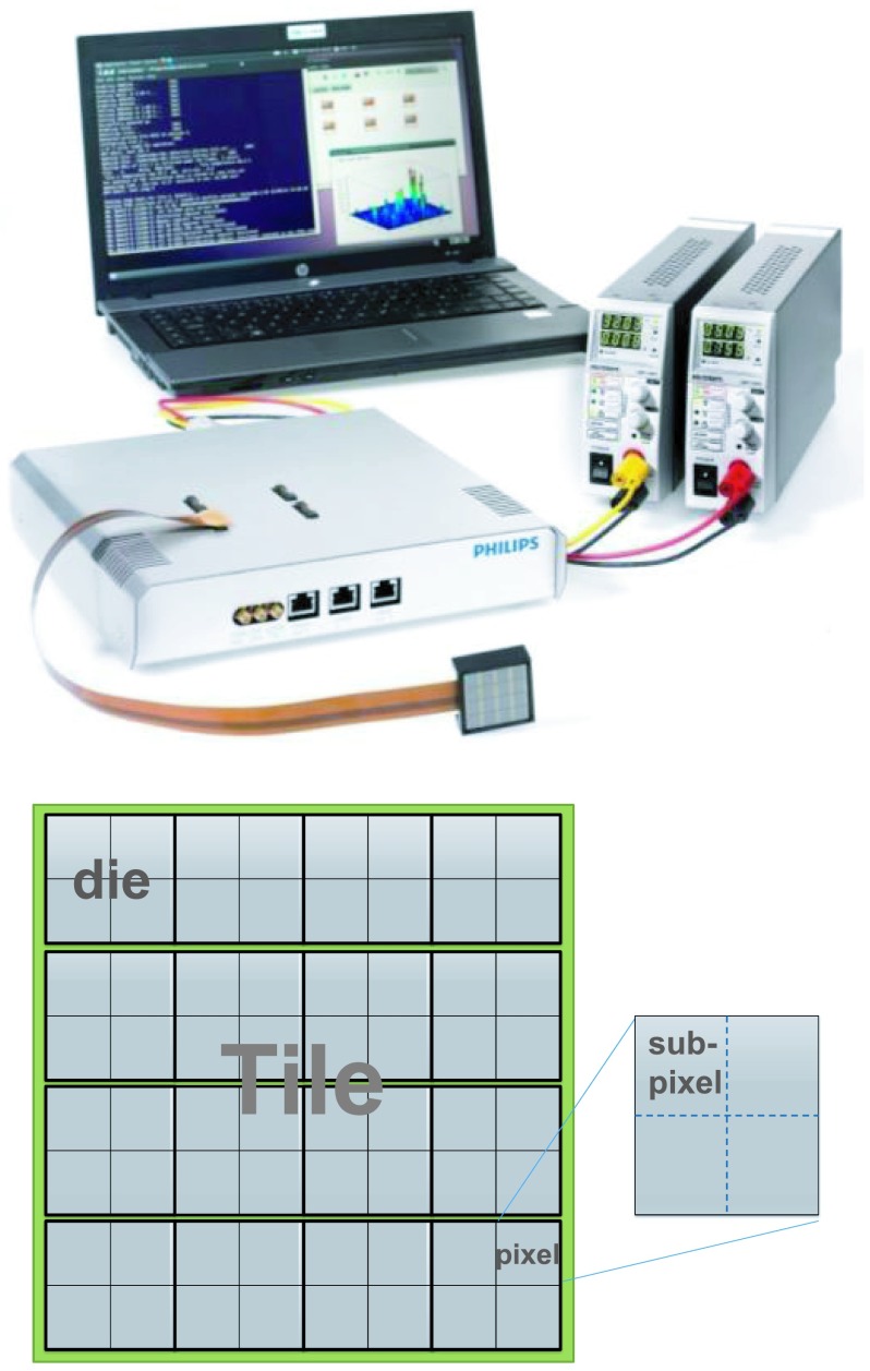
The dSiPM module used in this study is the technology evaluation kit (PDPC-TEK) consisting of two dSiPM tiles (outer dimension 32.6 × 32.6 mm2), a data acquisition module known as the base unit, power supplies, and a notebook with preinstalled software. A dSiPM tile comprises of 16 (in a 4 × 4 matrix) independent sensor dies (DPC-3200), each made up of a 2 × 2 SiPM pixel matrix, making up a total of 8 × 8 SiPM pixels per tile as illustrated in Fig. 2. Each pixel is 3.2 × 3.8775 mm2 in area and consists of 3200 microcells (∼60 μm microcell size). More detailed information regarding the sensor can be found in a paper by Haemisch et al.38 Any input signal that satisfies the preconfigured threshold conditions triggers the dSiPM for timestamp generation and initiates the data acquisition process. On-die digital circuitry generates timestamps of the trigger instant and counters count the number of microcell breakdowns caused by incoming light photons.
FIG. 2.
Picture of the dSiPM evalution kit taken from the user manual (top) and layout of the tile (bottom).
During the timestamp generation process, a single timestamp is generated by a pair of time-to-digital converters (TDCs) at the die level. That is, the 4 pixels in a die share a TDC pair to generate a single timestamp, meaning that a maximum of 16 timestamps can be generated by a single dSiPM tile. Within a single pixel, in order to trigger at different threshold levels (number of detected photons), each pixel has further been divided into four subpixels (see Fig. 2) and a total of four trigger schemes are supported based on the different Boolean interconnections of the four subpixels as explained in Table II. The first photon detected by a subpixel will produce a digital signal. Thus depending on the logic connection between the subpixels, each pixel can be set to trigger at different number of photons.
TABLE II.
Trigger schemes, corresponding logical subpixel connections and average number of photons required to generate a timestamp. The last column is the average number of photons required to trigger the pixel due to cumulative trigger probability, assuming photons are evenly irradiated on a pixel (data from dSiPM user manual).
| Trigger scheme | Logic connection | Average number of photons to trigger |
|---|---|---|
| 1 | sp1 ∨ sp2 ∨ sp3 ∨ sp4 | 1 |
| (sp1 ∨ sp2) ∧ (sp3 ∨ sp4) | ||
| 2 | ∨ | 2.33 |
| (sp1 ∨ sp4) ∧ (sp2 ∨ sp3)a | ||
| 3 | (sp1 ∨ sp2) ∧ (sp3 ∨ sp4) | 3.0 |
| 4 | sp1 ∧ sp2 ∧ sp3 ∧ sp4 | 8.33 |
“∧” represents the AND logic while “∨” represents OR logic. sp1 here represents subpixel 1 and so on.
3.B. Experimental setup
LYSO:Ce scintillation crystals with 3 × 3 mm2 cross-sectional area and different lengths were used to represent part of the detector configurations illustrated in Figs. 1(a), 1(b), and 1(d). For each configuration, a pair of single element crystals has been used for performance evaluation. The crystals and parameters used for this study are summarized in Table III.
TABLE III.
Specifications of the scintillation crystals for each readout configuration. The 20 and 5 mm length end-readout detector configurations are named as LE and SE, respectively, while the side-readout configuration with 20 mm length crystals is named LS.
| Parameters | End readout (LE) [Fig. 1(a)] | End readout (SE) [Fig. 1(b)] | Side readout (LS) [Fig. 1(d)] |
|---|---|---|---|
| Crystal | LYSO:Ce | LYSO:Ce | LYSO:Ce |
| Size (mm3) | 3 × 3 × 20 | 3 × 3 × 5 | 3 × 3 × 20 |
| Surface treatment | All sides polished | All sides polished | All sides polished |
| Reflector | Teflon | 3M ESR +Teflon top | Teflon |
| Coupling grease | BC-630 | BC-630 | BC-630 |
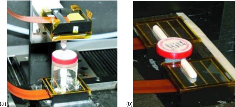
For each readout configuration, individual crystal element was coupled to a single dSiPM tile and placed head-on with a Na-22 point source (0.25 mm diameter) located between the crystal pairs as shown in Fig. 3. Coincidence annihilation photon events are stored in an acquisition PC to compute timing and energy resolutions of the setup. The entire setup was placed in a dark box with cooled dry streams of pressurized air directed at the dSiPM tiles to regulate the temperature of sensor. This cooled air was generated by a mechanical device known as the vortex tube that separates compressed gas, available in many laboratories, into hot and cold streams.39 The cold stream was fed into the dark box with a flexible tubing and further split into two streams, one for each dSiPM tile. By controlling the air valves of the vortex tube, the dSiPM sensor was regulated to about 15 °C during experiments. In all measurements performed, 5% of microcells with the highest dark count rate (DCR) and pixels not involved in the measurements were disabled.
FIG. 3.
Setup for measuring performance of LYSO crystals for the (a) end-readout and (b) side-readout configurations. Shown in the figure are 3 × 3 × 20 mm3 crystals.
For data acquisition, the preinstalled text based Linux program was used to acquire all events that satisfied the preconfigured trigger and validation level (amount of microcell discharges to consider an event as valid or invalid) but only save coincidence events that fall within a small timing window between the two tiles. The information in the output file (tile and die number, timestamp, pixel number and counts, event number, etc.) was then transferred to another PC for processing with c++ and matlab.
3.C. Skew correction
As explained above, there are 16 (in a 4 × 4 matrix) independent sensor dies in a dSiPM tile, each made up of 2 × 2 pixel matrices that generate a single timestamp. Between individual dies (TDCs), however, timing offsets (skew) due to clock signal generation and path length variations, etc., are present. These timing offsets between dies within a tile, which can be as large as several nanoseconds, can severely degrade timing performance of side-readout scintillators as well as for monolithic scintillators. In this study, the skew was determined using the setup depicted in Fig. 4. In the figure, to measure the time skew of the three dies of dSiPM-1 on which the 3 × 3 × 20 mm3 scintillator overlays, a small crystal was placed on one pixel of a die at a time and the timing spectrum with respect to a reference detector (dSiPM-2) was acquired. The variation in the centroid (mean) of the Gaussian fitted timing spectra as the crystal is physically moved across adjacent dies is a measure of the time skew between the dies within dSiPM-1. The same process was repeated to obtain the time skew in dSiPM-2.
FIG. 4.

Time skew in dSiPM-1, relative to Die1, can be computed from the mean of the timing spectra acquired with reference to a second detector (Ref. crystal on dSiPM-2) using (tDiex − tDie1 − tstep), where tstep = flight time of an annihilation photon between dies. Note, however, that in a given die, all 4 pixels are aligned in time.
3.D. Depth-of-interaction measurement
The DOI (or axial, z) resolution of the side-readout scintillation crystal was calculated based on the distribution of light photons across the dSiPM pixels on which the crystal overlays. Details of the method are explained in Refs. 36 and 40 and can be described as follows: the energy Ei of each dSiPM pixel i (i = 1, …, 6 in this study) at a given DOI position z can be described by the probability density function of a normally distributed function with mean μi and standard deviation σi,
For a detected set of energies [E1, …, E6] of a gamma interaction, the probability of it taking place at DOI position z is then given by
Based on the look up table (LUT) of μi and σi computed for finely segmented DOI positions, the maximum likelihood (ML) solution can be acquired by maximizing this probability. That is, the best estimate of the interaction position , for a measurement [E1, …, E6], is the value that maximizes equation
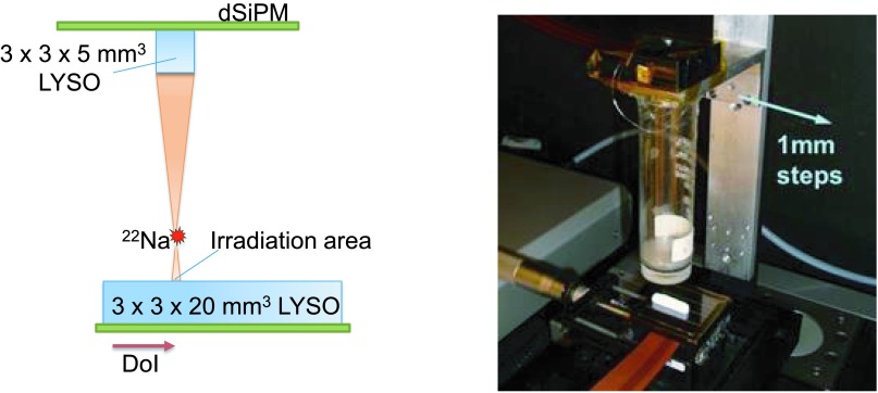
In order to compute the DOI resolution of the side-readout configuration of Fig. 1(d), the LUT of the means and standard deviations that describe a given DOI position as explained above have to be acquired. The setup to acquire the LUT is shown in Fig. 5. Here, a small 3 × 3 × 5 mm3 LYSO crystal was used as a reference to collimate the annihilation photons onto a small region on the side-readout crystal. The reference detector, along with the Na-22 radiation source, was swept across the entire side-readout LYSO crystal in 1 mm steps.
FIG. 5.
Illustration of the setup for DOI resolution measurement (left) and picture of the actual setup (right). Note the DOI direction in the left figure.
4. RESULTS
4.A. Energy resolution
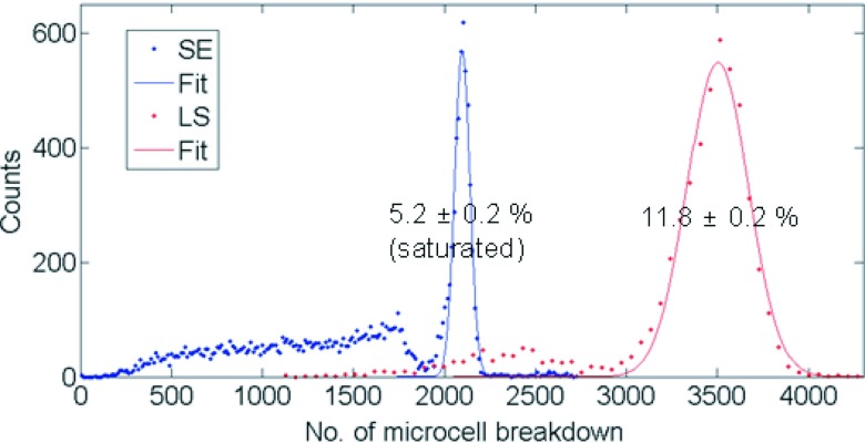
The dSiPM module was configured to save all data above a pre-set validation threshold along with its corresponding timestamps. Events that do not fall within a 20 ns coincidence window were discarded leaving only coincidence events in the acquisition PC. For end-readout crystals, the signal amplitude is the photon count value (number of microcell breakdowns) of the pixel on which each scintillation crystal is coupled. For side-readout crystals, photon count values from the 6 pixels on which the crystal is coupled are summed. The energy spectra for both end-readout scintillator configurations (LE and SE) were saturated due to the limited number of microcells relative to the incoming light photons, but the energy spectrum for side-readout configuration showed negligible saturation effect as the same number of light photons are spread over a much larger number of microcells. The Na-22 energy spectra acquired with 3 × 3 × 5 mm3 and side-readout 3 × 3 × 20 mm3 crystals have been plotted in Fig. 6. The 511 keV photopeaks were fitted with a Gaussian function and the energy resolutions (average of the two crystals in coincidence) were calculated to be 5.2% ± 0.2% (uncorrected for saturation) and 11.8% ± 0.2%, respectively. The error value represents the Gaussian fitting error (2 σ). Note that while automated energy (photon) saturation correction feature is available with the dSiPM module, it is experimental and has not been implemented in this study.
FIG. 6.
Typical energy spectra of coincident annihilation photons from a Na-22 source of the 3 × 3 × 5 mm3 end-readout LYSO crystal (SE) and 3 × 3 × 20 mm3 side-readout crystal (LS). The Gaussian-fitted 511 keV photopeaks are drawn in solid lines. The energy spectrum of end-readout 3 × 3 × 20 mm3 crystal is not shown as it largely overlaps with the blue curve with a photopeak centroid at ∼1900 microcell counts.
4.B. CRT
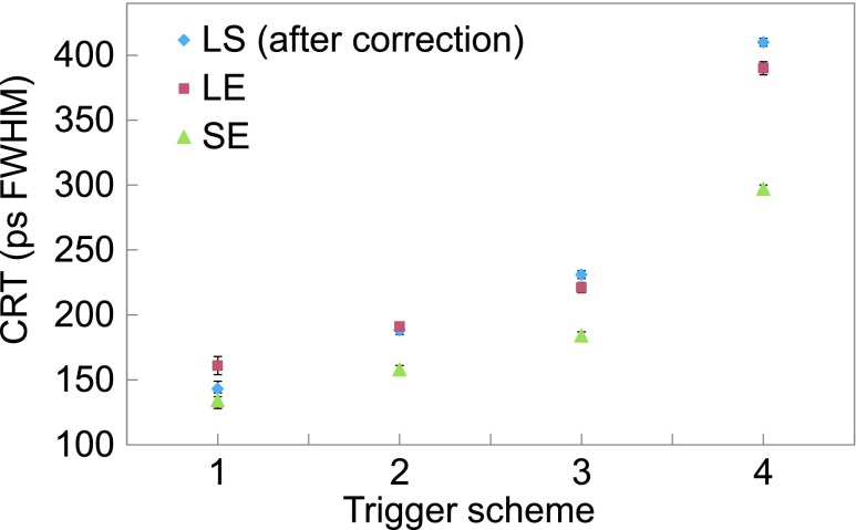
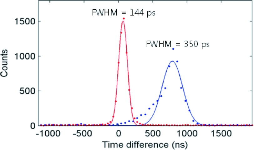
The timing performances of PET detectors are known to be highly dependent on the trigger levels. Therefore, the CRTs of the different configurations have been plotted as a function of trigger scheme (refer to Table II for photon number each scheme triggers) as summarized in Fig. 7. Only events that fall within a 3 σ bound of the 511 keV full energy photopeak coincident events were used. The timing performance was best when triggered at the first photon for all configurations. The CRT was 134 ± 6 ps for 3 × 3 × 5 mm3 end-readout and 162 ± 6 ps for 3 × 3 × 20 mm3 end-readout crystal configurations. The side-readout configuration of the 3 × 3 × 20 mm3 crystal demonstrated a noticeable improvement over the end-readout configuration with a CRT of 144 ± 2 ps after the skew correction described in Sec. 3.C was applied. The degradation of timing performance with trigger scheme was, however, more severe for the side-readout configuration (see Sec. 5 for discussion). The effect of time skew is evident in Fig. 8. Without skew correction, a non-Gaussian timing profile dependent on the amount of skew of the dies was acquired. In this setup, a timing resolution of ∼350 ps was measured without skew correction.
FIG. 7.
CRT of 3 × 3 × 5 mm3 end-readout crystal (SE), 3 × 3 × 20 mm3 end-readout crystal (LE), and 3 × 3 × 20 mm3 side-readout crystal (LS) configurations.
FIG. 8.
CRT of the 3 × 3 × 20 mm3 side-readout crystal configuration (LS) before (right peak) and after skew correction (left peak).
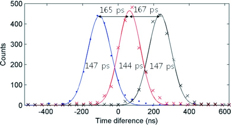
In order to validate the values obtained, one of the detector modules in the side-readout configuration was moved on a motorized stage away from the other detector and radiation source. Three sets of data were acquired in steps of 50 mm for a total of 100 mm (0, 50, and 100 mm). Trigger scheme 1 was selected and the acquired timing spectra are shown in Fig. 9. The time differences between two adjacent peaks are 165 ± 2 ps and 167 ± 2 ps which, using the speed of light, correspond to 49.8 ± 0.6 mm and 50.1 ± 0.6 mm separations, respectively.
FIG. 9.
Timing spectra and CRTs of side-readout 3 × 3 × 20 mm3 LYSO crystals at three different positions corresponding to 0, 50, and 100 mm from left to right.
4.C. DOI resolution for side-readout configuration
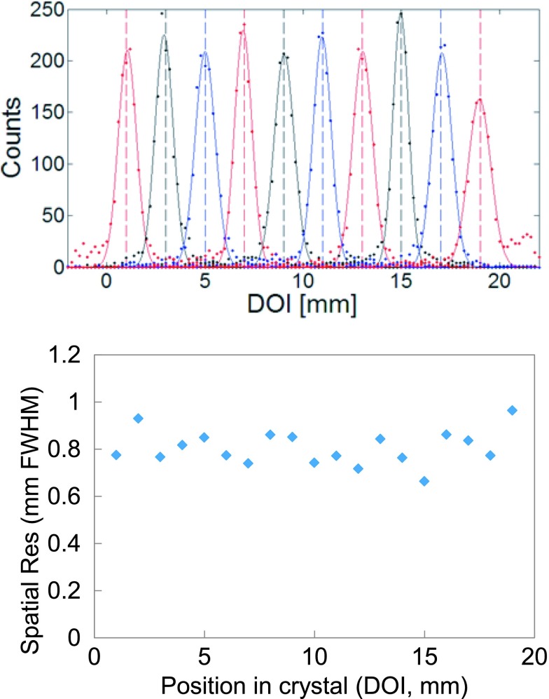
Based on the algorithm described in Sec. 3.D, the point spread function (PSF) along the 3 × 3 × 20 mm3 long LYSO has been plotted as in Fig. 10. Cubic spline interpolation was performed to acquire data every 0.2 mm. Only events that fall within 3 σ bound of the 511 keV full energy photopeak coincident events were used and the data were fitted with a Gaussian function to compute the DOI (or axial, z) resolution. The spatial resolution at each measurement point along the crystal is also plotted in Fig. 10 and the average DOI resolution was 0.80 ± 0.07 mm FWHM. The error value is the standard deviation of the data. The experimental results obtained from this study with discrete scintillation crystals are summarized in Table IV.
FIG. 10.
PSF of selected points separated by 0.2 mm along the 3 × 3 × 20 mm3 long LYSO (top) and spatial resolution as computed from the PSF (bottom).
TABLE IV.
Summary of the performance with end-readout and side-readout LYSO:Ce detector configurations.
| Crystal configuration | Energy resolution (%) | CRT (ps FWHM) | DOI resolution (mm FWHM) |
|---|---|---|---|
| 5 mm, end readout | Saturated | 134 ± 6 | NA |
| 20 mm, end readout | Saturated | 162 ± 6 | NA |
| 20 mm, side readout | 11.8 ± 0.2 | 144 ± 2 (>350a) | 0.8 ± 0.07 |
CRT when skew correction not applied. Dependent on degree of offset between dies.
5. SUMMARY AND DISCUSSION
The small 3 × 3 × 5 mm3 LYSO crystals showed the best timing performance, but with the 20 mm end-readout crystal size typically used in PET for stopping power, that value degraded by about 20% due to photon transport and light collection variations within the crystal.15 The side-readout configuration, with its much larger photosensor coupling area, leads to less light loss and lower transit time spread (variation in photon collection time), resulting in better timing performance comparable to short end-readout crystals. When skew correction was not applied to the same data, the timing spectrum skewed from its typical Gaussian distribution and produced highly degraded results. The larger coupling area (number of microcells) for the side-readout configuration also produces unsaturated energy resolution compared to end-readout configuration. Finally, a sub-millimeter DOI can be achieved with side-readout configuration by utilizing information of light distribution across the coupled photosensor pixels. With regards to saturation effects of SiPMs, it should be noted that energy saturation in itself may not degrade energy resolution and corrections can be performed offline to assess the true energy resolution of a detector. These methods should, however, be performed with care as the results are highly dependent on the correction function parameters, and detailed studies on saturation correction are out of scope of this paper.41,42
All measurements have been performed at a temperature regulated to around 15 °C (as measured with the temperature sensor on the dSiPM tile) with a vortex tube. Although cost effective, this cooling method could at best only cool the dSiPM tile down to about 10 °C, requires a pressurized dry air source near the setup, and the vented air produces an annoying amount of noise. Furthermore, a small and slow temperature fluctuation of 1 °C–2 °C from the regulated temperature was observed over the course of a day due to temperature and/or pressure changes in the main air line. However, that level of cooling and temperature shift is acceptable for our study as dSiPM is known to be generally less sensitive to temperature variations (photopeak and TDC drift of 0.33%/0.33 °C and 15.3 ps/15.3 °C, respectively).38
The side-readout configuration has the potential to overcome some of the shortcomings of monolithic detectors (single block or stacked monolithic). The side-readout configuration achieved a better energy resolution (especially at higher temperatures) compared to the monolithic designs likely due to lower accumulation of dark counts during signal integration.9,35 Also, the additional degradation of timing resolution at higher trigger levels due to light spread that occurs in monolithic crystals, while also evident in the side-readout configuration (Fig. 7), is largely mitigated for the latter due to coupling to a much smaller number of photosensors (note that this degradation is nonexistent only when triggered at the first photon). From Fig. 7, it is clear that even though the timing resolution degradation at higher trigger levels is worse compared to end-readout detectors, the timing resolution is still excellent up to trigger scheme 3 defined in Table II—which is crucial if the dSiPM is to be operated close to room temperatures. The actual trigger scheme to be used would depend on the regulated temperature and amount of counts (sensitivity) one is willing to compromise for timing. At higher trigger schemes, there will be fewer triggers by dark counts and thus lower probability of another event during the dSiPM deadtime.
That said, as mentioned earlier, the timing resolution of the results acquired from this study can be further improved by using faster/brighter scintillators like Ca-codoped LSO:Ce (Refs. 43 and 44) and/or by further cooling the detector module down to lower temperatures.38,45 It may also be possible to improve the timing performance further with a better skew correction method. For this study, we performed the correction by physically moving a crystal from die to die and inferring the skew from the shift in timing spectra (see Sec. 3.C). This process, while straightforward in our setup, can be cumbersome to perform on entire tiles and may be prone to larger error than by utilizing, for example, a fast pulsed laser system that outputs a reference trigger along with a laser pulse and by irradiating each pixel within the tile to obtain accurate time skew values between dies.30 Finally, although not implemented in this study, it may also be possible to reduce the timing resolution by taking into account the 511 keV photon flight time within the side-readout configuration. However, the effect is likely to be very small (∼few nanoseconds) when added in quadrature with the timing resolution of the detector. To improve the DOI resolution, brighter scintillation crystals like Ce:GAGG could be used.46
6. CONCLUSION
In this proof of concept study, we have experimentally demonstrated that side readout of light photons from long scintillation crystals in PET detectors has the potential to achieve excellent DOI and energy resolutions while still preserving excellent timing resolution. Scaling side-readout detectors up to a full system, however, can be challenging due to detector complexity (packing, cooling, etc.) and comes at the expense of increased number of photosensors and electronics.47–49 In that respect, physically thinner photosensors would be beneficial in consideration of detector packing fraction of complete PET systems. Finally, we conclude from this study that the side-readout detector configuration can be appropriate for small animal PET systems that would benefit from fine DOI resolution and may also be an attractive configuration for PET systems requiring both TOF timing performance and fine DOI resolution, such as brain dedicated systems.
ACKNOWLEDGMENTS
This study is supported in part by the quality of working life (QWL) program funded by the Ministry of Trade, Industry and Energy of South Korea, National Research Foundation of Korea (NRF-2014R1A1A1005242), “Creative ICT Convergence Human Resource Development” support program (NIPA-2014-H7501-14-1002) supervised by NIPA (National IT Industry Promotion Agency), NIH-NIBIB Grant No. R21EB014405, and a grant from Philips Healthcare. The authors would like to thank Matthew Bieniosek of Stanford University for useful dicussions, and Virginia Spanoudaki, David Sowards-Emmerd and Ralf Schulze of Philips for support with the use of dSiPM.
REFERENCES
- 1.Peng B. H. and Levin C. S., “Recent development in PET instrumentation,” Curr. Pharm. Biotechnol. 11, 555–571 (2010). 10.2174/138920110792246555 [DOI] [PMC free article] [PubMed] [Google Scholar]
- 2.Cherry S. R. and Dahlbom M., “PET: Physics, instrumentation, and scanners,” in M. E. Phelps, PET: Molecular imaging and its biological applications (Springer, New York, 2004). [Google Scholar]
- 3.Tai Y.-C. and Laforest R., “Instrumentation aspects of animal PET,” Annu. Rev. Biomed. Eng. 7, 255–285 (2005). 10.1146/annurev.bioeng.6.040803.140021 [DOI] [PubMed] [Google Scholar]
- 4.Gu Y.et al. , “Study of a high-resolution, 3D positioning cadmium zinc telluride detector for PET,” Phys. Med. Biol. 56(6), 1563–1584 (2011). 10.1088/0031-9155/56/6/004 [DOI] [PMC free article] [PubMed] [Google Scholar]
- 5.MacDonald L. R. and Dahlbom M., “Parallax correction in PET using depth of interaction information,” IEEE Trans. Nucl. Sci. 45, 2232–2237 (1998). 10.1109/23.708354 [DOI] [Google Scholar]
- 6.Lerche C. W.et al. , “Depth of interaction detection for gamma-ray imaging,” Nucl. Instrum. Methods Phys. Res., Sect. A 600, 624–634 (2009). 10.1016/j.nima.2008.11.151 [DOI] [Google Scholar]
- 7.Schaart D. R.et al. , “A novel, SiPM-array-based, monolithic scintillator detector for PET,” Phys. Med. Biol. 54, 3501–3512 (2009). 10.1088/0031-9155/54/11/015 [DOI] [PubMed] [Google Scholar]
- 8.Sánchez F.et al. , “Small animal PET scanner based on monolithic LYSO crystals: Performance evaluation,” Med. Phys. 39, 643–653 (2012). 10.1118/1.3673771 [DOI] [PubMed] [Google Scholar]
- 9.España S., Marcinkowski R., Keereman V., Vandenberghe S., and Van Holen R., “DigiPET: Sub-millimeter spatial resolution small-animal PET imaging using thin monolithic scintillators,” Phys. Med. Biol. 59, 3405–3420 (2014). 10.1088/0031-9155/59/13/3405 [DOI] [PubMed] [Google Scholar]
- 10.Blanco A.et al. , “RPC-pet: A new very high resolution PET technology,” IEEE Trans. Nucl. Sci. 53, 2489–2494 (2006). 10.1109/TNS.2006.876005 [DOI] [Google Scholar]
- 11.Buzhan P.et al. , “Silicon photomultiplier and its possible applications,” Nucl. Instrum. Methods Phys. Res., Sect. A 504, 48–52 (2003). 10.1016/S0168-9002(03)00749-6 [DOI] [Google Scholar]
- 12.Spanoudaki V. C. and Levin C. S., “Photo-detectors for time of flight positron emission tomography (ToF-PET),” Sensors 10, 10484–10505 (2010). 10.3390/s101110484 [DOI] [PMC free article] [PubMed] [Google Scholar]
- 13.Yeom J. Y.et al. , “Fast timing silicon photomultipliers for scintillation detectors,” IEEE Photonics Technol. Lett. 25, 1309–1312 (2013). 10.1109/LPT.2013.2264049 [DOI] [Google Scholar]
- 14.Schaart D. R.et al. , “LaBr(3):Ce and SiPMs for time-of-flight PET: Achieving 100 ps coincidence resolving time,” Phys. Med. Biol. 55, N179–N189 (2010). 10.1088/0031-9155/55/7/N02 [DOI] [PubMed] [Google Scholar]
- 15.Yeom J. Y., Vinke R., and Levin C. S., “Optimizing timing performance of silicon photomultiplier-based scintillation detectors,” Phys. Med. Biol. 58, 1207–1220 (2013). 10.1088/0031-9155/58/4/1207 [DOI] [PMC free article] [PubMed] [Google Scholar]
- 16.Yeom J. Y., Vinke R., Spanoudaki V. C., Hong K. J., and Levin C. S., “Readout electronics and data acquisition of a positron emission tomography time-of-flight detector module with waveform digitizer,” IEEE Trans. Nucl. Sci. 60(5), 3735–3741 (2013). 10.1109/TNS.2013.2264947 [DOI] [Google Scholar]
- 17.Levin C., Deller T., Peterson W., Maramraju S. H., Kim C., and Prost R., “Initial results of simultaneous whole-body ToF PET/MR,” J. Nucl. Med. 55, 660 (2014). [Google Scholar]
- 18.Miller M.et al. , “Initial characterization of a prototype digital photon counting PET system,” J. Nucl. Med. 55, 658 (2014). [Google Scholar]
- 19.Moses W. W., “Recent advances and future advances in time-of-flight PET,” Nucl. Instrum. Methods Phys. Res., Sect. A 580, 919–924 (2007). 10.1016/j.nima.2007.06.038 [DOI] [PMC free article] [PubMed] [Google Scholar]
- 20.Karp J. S., Surti S., Daube-Witherspoon M. E., and Muehllehner G., “Benefit of time-of-flight in PET: Experimental and clinical results,” J. Nucl. Med. 49, 462–470 (2008). 10.2967/jnumed.107.044834 [DOI] [PMC free article] [PubMed] [Google Scholar]
- 21.Chandrikamohan P. and DeVol T. A., “Comparison of pulse shape discrimination methods for phoswich and CsI: Tl detectors,” IEEE Trans. Nucl. Sci. 54, 398–403 (2007). 10.1109/TNS.2007.892943 [DOI] [Google Scholar]
- 22.Seidel J., Vaquero J. J., Siegel S., Gandler W. R., and Green M. V., “Depth identification accuracy of a three layer phoswich PET detector module,” IEEE Trans. Nucl. Sci. 46, 485–490 (1999). 10.1109/23.775567 [DOI] [Google Scholar]
- 23.Jung J. H.et al. , “Optimization of LSO LuYAP phoswich detector for small animal PET,” Nucl. Instrum. Methods Phys. Res., Sect. A 571, 669–675 (2007). 10.1016/j.nima.2006.10.293 [DOI] [Google Scholar]
- 24.Du H., Yang Y., Glodo J., Wu Y., Shah K., and Cherry S. R., “Continuous depth-of-interaction encoding using phosphor-coated scintillators,” Phys. Med. Biol. 54, 1757–1771 (2009). 10.1088/0031-9155/54/6/023 [DOI] [PMC free article] [PubMed] [Google Scholar]
- 25.Streun A.et al. , “Pulse shape discrimination of LSO and LuYAP scintillators for depth of interaction detection in PET,” IEEE Trans. Nucl. Sci. 50, 344–347 (2003). 10.1109/TNS.2003.812449 [DOI] [Google Scholar]
- 26.Tsuda T.et al. , “Performance evaluation of a subset of a four-layer LSO detector for a small animal DOI PET scanner: Jpet-rd,” IEEE Trans. Nucl. Sci. 53, 35–39 (2006). 10.1109/TNS.2005.862961 [DOI] [Google Scholar]
- 27.Beltrame P.et al. , “AX-PET: Concept, proof of principle and first results with phantoms,” in IEEE Nuclear Science Symposium Conference on Medical Imaging (IEEE, Knoxville, TN, 2010), pp. 2754–2757 10.1109/NSSMIC.2010.5874294 [DOI] [Google Scholar]
- 28.Yang Y.et al. , “Depth of interaction calibration for PET detectors with dual-ended readout by PSAPDs,” Phys. Med. Biol. 54, 433–445 (2009). 10.1088/0031-9155/54/2/017 [DOI] [PMC free article] [PubMed] [Google Scholar]
- 29.Ito M.et al. , “A four-layer DOI detector with a relative offset for use in an animal PET system,” IEEE Trans. Nucl. Sci. 57, 976–981 (2010). 10.1109/TNS.2010.2044892 [DOI] [Google Scholar]
- 30.van Dam H. T., Borghi G., Seifert S., and Schaart D. R., “Sub-200 ps CRT in monolithic scintillator PET detectors using digital SiPM arrays and maximum likelihood interaction time estimation,” Phys. Med. Biol. 58, 3243–3257 (2013). 10.1088/0031-9155/58/10/3243 [DOI] [PubMed] [Google Scholar]
- 31.Levin C. S., “Design of a high-resolution and high-sensitivity scintillation crystal array for PET with nearly complete light collection,” IEEE Trans. Nucl. Sci. 49, 2236–2243 (2002). 10.1109/TNS.2002.803870 [DOI] [Google Scholar]
- 32.Moses W. W.et al. , “Optimization of a LSO-based detector module for time-of-flight PET,” IEEE Trans. Nucl. Sci. 57, 1570–1576 (2010). 10.1109/TNS.2010.2047266 [DOI] [PMC free article] [PubMed] [Google Scholar]
- 33.Vinke R. and Levin C. S., “A method to achieve spatial linearity and uniform resolution at the edges of monolithic scintillation crystal detectors,” Phys. Med. Biol. 59, 2975–2995 (2014). 10.1088/0031-9155/59/12/2975 [DOI] [PubMed] [Google Scholar]
- 34.Chen Z.et al. , “Optimum performance investigation of LYSO crystal pixels: A comparison between GATE simulation and experimental data,” e-print arXiv:1309.3736v1 [physics.ins-det] (2013).
- 35.Seifert S., van der Lei G., van Dam H. T., and Schaart D. R., “First characterization of a digital SiPM based time-of-flight PET detector with 1 mm spatial resolution,” Phys. Med. Biol. 58, 3061–3074 (2013). 10.1088/0031-9155/58/9/3061 [DOI] [PubMed] [Google Scholar]
- 36.Vinke R.et al. , “Time walk correction for TOF-PET detectors based on a monolithic scintillation crystal coupled to a photosensor array,” Nucl. Instrum. Methods Phys. Res., Sect. A 621(1–3), 595–604 (2010). 10.1016/j.nima.2010.05.034 [DOI] [Google Scholar]
- 37.Frach T., Prescher G., Degenhardt C., and Zwaans B., “The digital silicon photomultiplier—System architecture and performance evaluation,” in IEEE Nuclear Science Symposium Conference on Medical Imaging (IEEE, Knoxville, TN, 2010), pp. 1722–1727. [Google Scholar]
- 38.Haemisch Y., Frach T., Degenhardt C., and Thon A., “Fully digital arrays of silicon photomultipliers (dSiPM)—A scalable alternative to vacuum photomultiplier tubes (PMT),” Phys. Procedia 37, 1546–1560 (2012). 10.1016/j.phpro.2012.03.749 [DOI] [Google Scholar]
- 39.Aljuwayhel N. F., Nellis G. F., and Klein S. A., “Parametric and internal study of the vortex tube using a CFD model,” Int. J. Refrig. 28, 442–450 (2005). 10.1016/j.ijrefrig.2004.04.004 [DOI] [Google Scholar]
- 40.Joung J., Miyaoka R. S., Kohlmyer S., and Lewellen T. K., “Implementation of ML based positioning algorithms for scintillation cameras,” IEEE Trans. Nucl. Sci. 47, 1104–1111 (2000). 10.1109/23.856555 [DOI] [Google Scholar]
- 41.Yeom J. Y.et al. , “First performance results of Ce:GAGG scintillation crystals with silicon photomultipliers,” IEEE Trans. Nucl. Sci. 60, 988–992 (2013). 10.1109/TNS.2012.2233497 [DOI] [Google Scholar]
- 42.Degenhardt C.et al. , “The digital silicon photomultiplier—A novel sensor for the detection of scintillation light,” in IEEE Nuclear Science Symposium Conference Record (NSS/MIC) (IEEE, Orlando, FL, 2009), pp. 2383–2386. [Google Scholar]
- 43.Spurrier M. A., Szupryczynski P., Yang K., Carey A. A., and Melcher C. L., “Effects of Ca 2+ co-doping on the scintillation properties of LSO: Ce,” IEEE Trans. Nucl. Sci. 55, 1178–1182 (2008). 10.1109/TNS.2007.913486 [DOI] [Google Scholar]
- 44.Bisogni M. G., Collazuol G. M., Marcatili S., Melcher C. L., and Del Guerra A., “Characterization of Ca co-doped LSO: Ce scintillators coupled to SiPM for PET applications,” Nucl. Instrum. Methods Phys. Res., Sect. A 628, 423–425 (2011). 10.1016/j.nima.2010.07.016 [DOI] [Google Scholar]
- 45.Feng H.et al. , “Cerium concentration and temperature dependence of the luminescence of Lu2Si2O7:Ce scintillator,” J. Alloys Compd. 509, 3855–3858 (2011). 10.1016/j.jallcom.2010.12.124 [DOI] [Google Scholar]
- 46.Kamada K.et al. , “2 inch diameter single crystal growth and scintillation properties of Ce:Gd3Al2Ga3O12,” J. Crystal Growth 352, 88–90 (2012). 10.1016/j.jcrysgro.2011.11.085 [DOI] [Google Scholar]
- 47.Vandenbroucke A., Foudray A. M. K., Olcott P. D., and Levin C. S., “Performance characterization of a new high resolution PET scintillation detector,” Phys. Med. Biol. 55, 5895–5911 (2010). 10.1088/0031-9155/55/19/018 [DOI] [PMC free article] [PubMed] [Google Scholar]
- 48.Levin C. S., “Promising new photon detection concepts for high-resolution clinical and preclinical PET,” J. Nucl. Med. 53, 167–170 (2012). 10.2967/jnumed.110.084343 [DOI] [PMC free article] [PubMed] [Google Scholar]
- 49.Bieniosek M. F., Olcott P. D., and Levin C. S., “Compact pulse width modulation circuitry for silicon photomultiplier readout,” Phys. Med. Biol. 58, 5049–5059 (2013). 10.1088/0031-9155/58/15/5049 [DOI] [PMC free article] [PubMed] [Google Scholar]


