Abstract
A novel compact and lightweight patient-mounted MRI-compatible robot has been designed for MRI image-guided interventions. This robot is intended to enable MRI-guided needle placement as done in shoulder arthrography. The robot could make needle placement more accurate and simplify the current workflow by converting the traditional two-stage arthrography procedure (fluoroscopy-guided needle insertion followed by a diagnostic MRI scan) to a one-stage procedure (streamlined workflow all in MRI suite). The robot has 4 degrees of freedom (DOF), two for orientation of the needle and two for needle positioning. The mechanical design was based on several criteria including rigidity, MRI compatibility, compact design, sterilizability, and adjustability. The proposed workflow is discussed and initial MRI compatibility experiments are presented. The results show that artifacts in the region of interest are minimal and that MRI images of the shoulder were not adversely affected by placing the robot on a human volunteer.
I. INTRODUCTION
Arthrography is the evaluation of joint condition using imaging modalities such as computed tomography (CT) and magnetic resonance imaging (MRI). The average American child between the ages of 5-14 will experience one sports-related injury during that time period [1]. A significant portion of these injuries will involve internal derangements of shoulders, hips, wrists, and other joints [1]. Magnetic resonance (MR) arthrography is the modality of choice for evaluation of suspected derangement of articular labral structures, untreated congenital joint dysplasias, articular cartilage, and other internal structures of the joint since it has higher soft tissue contrast in comparison to other modalities. Currently, arthrography requires two separate stages, an intra-articular contrast injection guided by fluoroscopy or ultrasound followed by an MRI. While MRI could also be used for guiding the needle placement, patient access in MRI can be difficult, especially for closed bored scanners. Therefore, the development of a small, body-mounted robot to assist in needle placement in the MRI environment could streamline the procedure.
The current two-step workflow can result in anxiety for the patient, prolonged sedation time when sedation is needed for younger patients, radiation exposure from the fluoroscopic imaging, and may increase cost due to the use of both the fluoroscopy and MRI suite. Our goal therefore is to develop an MRI-compatible shoulder arthrography robot to enable one-stage procedures in the MRI environment. This robot will also provide a stable guide for the needle and may reduce the number of needle passes by providing a steady and precise needle holder. The latter will reduce trauma to patient and reduce the burden to the physician.
The high-strength magnetic field currently present in the clinical MRI environment makes developing MRI-compatible equipment a challenge. Nonmagnetic materials, MRI-compatible actuators (piezo-motors, pneumatic and hydraulic actuators), optical encoders, and sensors are key elements of these robotic systems. A few research groups have reported related work in the field of patient-mounted robots for percutaneous interventions. Walsh et al. [2] developed a patient-mounted robot called Robopsy. This was a system with 4 DOF for needle holding, guidance, and insertion. The robot was attached to the patient via an adhesive pad and optional strap points, so the device could move passively with patient motion and was thus inherently safe. An MRI coil-mounted robotic positioner for cryoablation was developed in [3]. This 2 DOF, cable-driven robot had a multi-probe head for decreasing the ablation time. The robot could orient the intervention probes about a remote center of motion (RCM). However, the needle entry point had to be found and marked before attaching the robot to the patient, since the robot had only 2 rotational DOF. Maurin et al. [4] developed a patient-mounted robot using a 5 DOF parallel structure with a semispherical workspace, particularly well-suited to CT-based interventional procedures. A new robotic architecture was developed to perform interventional CT/MR procedures using both ultrasonic motors and pneumatic motors to position the needle and then insert it progressively. The whole robot could be sterilized and its mechanical positioning error was less than 5mm [5]. Bricault et al. [6] developed a light (1Kg) and compact (15×23cm) robot with 5 DOFs to perform abdominal and thoracic punctures under CT or MRI guidance for diagnostic or therapeutic purposes. The robot translation accuracy was 1mm. Rotation and inclination accuracy was less than 1°. Compressed air was used as the energy source. Song et al. developed a 2 DOF MRI-compatible double ring RCM mechanism for MRI-guided liver interventions. This device was a passive mechanism which was manually operated [7].
In this paper a novel MRI-compatible patient-mounted robotic system is introduced which could provide better targeting, improved clinical workflow, and allow better access with cylindrical bore MRI scanners. Our mechanical design results in a minimal height profile which is an important issue considering the small diameter of the MRI scanner’s bore (typically 60 cm). Also, our design should make it possible to wrap most of the robot with a sterile drape to provide a cheap and easy solution for sterilization. The unique design of the mounting legs will enable the robot to sit on non-flat surfaces. While our primary clinical application is arthrography, other MRI image-guided needle placement procedures such as injection (e.g. facet joint injection), biopsy (e.g. lung, liver), and lesion ablation are also potential applications for this robot.
The remainder of this paper is organized as follows. First we present our new proposed clinical workflow in Section II. We then discuss the mechanical design in Section III. A kinematic analysis is given in Section IV, followed by experimental results in Section V. Conclusions are given in Section VI.
II. CLINICAL WORKFLOW
The proposed workflow is described in the following ten steps as shown in the flowchart in Figure 1:
Step 1: The patient will be positioned in the MRI scanner.
Step 2: The robot will be attached to the patient body based on a rough estimation of the target area (shoulder joint). The adjustable legs will sit on top of the shoulder area. Using adhesive pads and tapes, the robot will be securely positioned on the body.
Step 3: The patient will be moved into the scanner bore. A first set of images will be acquired using the spine coil built into the patient table. Using passive fiducial markers incorporated into robot body, robot-to-patient registration will be performed.
Step 4: Based on the images, the radiologist will select the patient’s joint space (target needle point) and the entrance point on the skin.
Step 5: The robot will be registered with the image space using fiducials. The robot is then actuated to align the needle along the line connecting the skin entry point and target point in the joint space.
Step 6: The patient will be moved out of the scanner bore. The radiologist will insert the needle through the needle guide until the needle hits the bone in the joint space.
Step 7: To ensure the needle is in the right place, the patient will be moved into the scanner to take confirmation images.
Step 8: The patient will be moved out of the scanner to connect the syringe and to inject the contrast agent to the patient’s joint.
Step 10: The patient will be moved into the scanner for the last time to take diagnostic images.
Figure 1.
Proposed 10-step clinical workflow.
III. Mechanical design
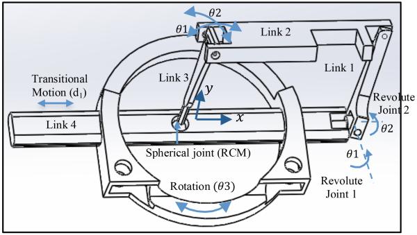
As shown in Fig. 2, a four-link parallel mechanism with a spherical joint is used, yielding 2 rotational DOF about the spherical joint, θ1 and θ2, and 2 DOF for needle positioning. The four-link parallel mechanism base, link 4, slides through the robot base to add the third DOF, d1. The combination of this transitional motion with the rotation of the robot base, θ3, provides maneuverability in the x y plane.
Figure 2.
Schematic of the parallel robot.
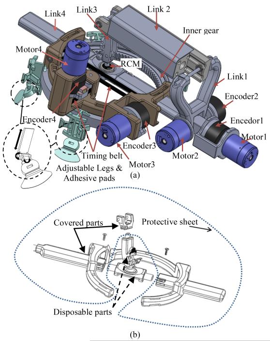
As shown in the CAD model in Fig. 3(a), motor 1 and motor 2 rotate the needle with respect to the spherical joint to provide the 2 rotational DOFs. Motor 3 provides translational motion along link 4 through a timing belt and a pair of pulleys.
Figure 3.
CAD model of the final design (a) patient-mounted robot (b) disposable parts and covered parts.
The design requirements of the robot were as follows:
4 DOF robot, with 2 DOFs for needle positioning and 2 DOFs for needle orientation;
Compact;
Rigid structure;
Ease of attachment to the patient body;
Adjustable mechanism to fit different size patients;
Ease of sterilization;
MRI safe and MRI-compatible;
Simplified workflow while maintaining image quality;
User-friendly interface.
These criteria have been considered and addressed as described below:
4 DOF robot
In typical interventional procedures, first a tomographic scan is performed and then the skin entry point is selected by the radiologist. The hand-eye calibration is done intuitively by the radiologist who requires a great deal of training. Based on the images and a deep understanding of the anatomy, the radiologist places, orients, and inserts the needle in a specific direction through the marked point on the skin to reach the target. For automating this procedure, 4 DOFs are required: 2 DOFs for moving the needle to reach the appropriate point on the skin; and 2 DOFs for orienting the needle along the line to the target.
Small size
The robot is designed to be mounted on the patient’s body while he/she is inside the MRI scanner bore. The diameter of the scanner bore is typically 60 cm which limits the overall robot workspace. Therefore, the height profile of the robot should be minimized. The overall dimensions of the robot are: 300 mm length, 130 mm width, and 100 mm height. The robot’s workspace is a circular area of 10 cm in diameter for translational motion and ±45 ° for rotational degrees of freedom for needle orientation.
Rigid structure
The robot requires a rigid structure to avoid any error in needle placement. Errors may occur if the mechanism deforms while the needle is driven into the patient’s joint. A parallel structure with a RCM has been selected to make the robot small and rigid at the same time.
Ease of attachment
MRI time is very expensive. In robotic assisted arthrography, the procedure time should be as short as possible. Therefore, the attachment of the robot should be easy and fast. In the proposed design, by using adhesive pads and tape, the robot can be easily and quickly attached. The goal is to be able to attach the robot to the patient’s body in less than 3 minutes.
Adjustable mechanism
Due to the variation in patient size and different target joints in arthrography (shoulder, hip, elbow, etc.), the robot should be adjustable for different situations. As shown in Fig. 3(a), four passive adjustable legs are part of the robot design. Each leg has 3 DOFs and can be easily adjusted for different applications. Each leg has an adhesive pad which sits and sticks on the skin.
Ease of sterilization
For medical robotic systems, sterilization is a critical issue that must be addressed. We considered three possibilities: 1) make the robot disposable, 2) use special material and sealing to make the robot sterilizable, 3) cover the robot with an appropriate protective sheet to avoid exposure of the robot to the environment. None of these methods alone seemed optimal for our application.
Therefore, we combined these methods for sterilization. As shown in Fig. 3(b), by separating link 4 into three parts and link 3 into two parts, it is possible to cover most parts of the robot with a protective sheet, and then assemble pieces of the links 3 and 4 together. The parts that are not covered can be either disposable or sterilizable.
MRI-safe and MRI-compatible
Ferromagnetic materials are hazardous in the MRI room. Therefore, the robot should be made of non-ferromagnetic materials, nonmagnetic actuators, and sensors. The robot should also be MRI-compatible.
Non-ferromagnetic metal part still can cause artifacts in the images. In robotic assisted arthrography application where the robot sits directly above the imaging target, compatibility must be considered. In this paper, some experiments have been performed to investigate the MRI compatibility of the robot, particularly for a shoulder arthrography procedure.
Simplified workflow while maintaining image quality
While a flexible coil is usually used for acquiring diagnostic images for shoulder arthrography, this coil may interfere with robot placement in robotic assisted arthrography. For the robotically assisted procedure, one option is to use a single coil [7] which can placed under the robot or a custom made coil embedded to the robot’s base. However, this coil may not give the high quality diagnostic images needed after contrast injection. Therefore, in our proposed clinical workflow, as described in Section II, we started by using the spine coil built into the table for robot-to-patient registration, needle alignment and insertion without any flexible coil. A flexible coil will later be utilized for obtaining diagnostic images after the robot is removed.
User-friendly interface
For control of the robot, we envision two possibilities: 1) a master-slave configuration, in which the physician can control the robot from the MRI control room with a standard joystick or with a MRI-compatible joystick from inside the MRI room; and 2) a positioning mode, in which the robot pre-aligns the needle into the desired trajectory automatically and the physician would then manually drive the needle to the target while the robot maintains the desired trajectory. Both user interfaces will be investigated in future work.
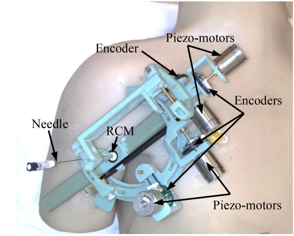
Fig. 4 shows our prototype robot made by a rapid prototyping machine (Objet 500, Stratasys) using ABS material. MRI-compatible piezo-motors (Piezo LEGS® Upsala, Sweden), and MRI-compatible encoders (E8P OEM Optical Kit Encoder, 512 CPR, US digital, Vancouver, Washington, USA) are used for actuation and measurement.
Figure 4.
Prototype of the robot made mostly of ABS material mounted on a body phantom.
IV. Robot kinematics
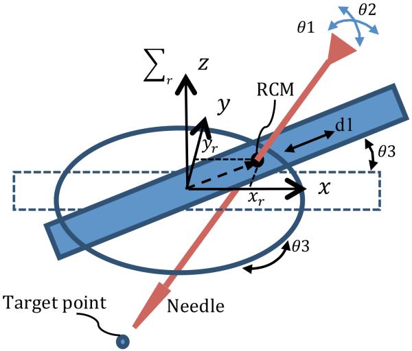
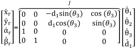
In this section, the kinematic equations for the robot are derived in the robot coordinate system. The transformation matrix from robot coordinate system to image coordinate system allows the physician to select the desired target point in the image and command the robot to align the needle towards the target. Fig. 5 shows the robot configuration and the parameters used to define the kinematics. The kinematic equations for this 4-DOF robot are as follows:
| (1) |
| (2) |
| (3) |
 |
(4) |
where xr and yr are the translational components of the needle coordinate vector in the robot coordinate system (Σr). αr and βr are the rotational components of the needle coordinate vector in the robot coordinate system. J is the Jacobian matrix.
Figure 5.
The robot is shown with its 4th DOF rotated to show 3rd DOF moved for linearly.
V. Experiments and Results
The goals of these experiments were: a) to study the distortions caused by the robot and piezo-motors, and b) to investigate the possibility of using the embedded spine coil of the MRI scanner for needle placement in the shoulder joint. Each of the goals were addressed as follows:
A. Study of distortions caused by the robot and motors
Three different sets of images were obtained: 1) MRI images of a grating phantom, which is used as a ground truth, 2) MRI images of one piezo-motor placed on top of the grating phantom, and 3) MRI images of the grating phantom with the robot placed on top.
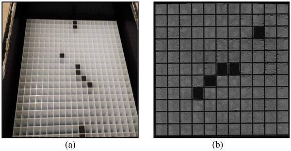
Fig. 6(a) shows the grating phantom. An MRI image from our 1.5 Tesla Siemens scanner for this phantom is shown in Fig. 6(b). The cross lines in the images will show any distortion caused by artifacts. In this image there is no artifact or distortion since there is nothing on top of the phantom.
Figure 6.
Grating phantom with 1 cm by 1 cm cube. (a) Photograph (b) MRI image of part of the phantom.
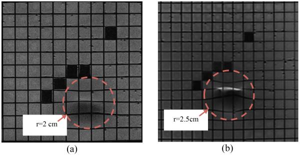
In the next step, the distortions due to the actuators were studied. One of the piezo-motors was placed on the top of the grating phantom and new images were acquired. Fig. 7 shows the results in two different coronal planes. Fig. 7(a) shows the coronal plane under the motor. Fig. 7(b) shows a coronal plane closer to the surface of the grating phantom.
Figure 7.
Distorted areas are seen in MRI images of the grating phantom when the piezo-motor is placed at the isocenter on top of it. Coronal plane under motor (a). Coronal plane closer to grating phantom (b).
As shown in these figures the maximum distortion can be measured in Fig. 7(b). By investigating the images, we determined that the artifacts caused by the piezo-motors result in 2.5 cm distortion in the image in all directions. This result means that appropriate mechanical design is necessary to guarantee that the motors will be more than 2.5 cm away from the targeting area to avoid distortion on images.
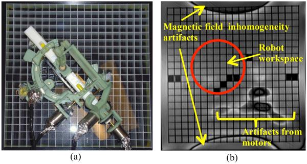
In the next step, the robot with motors attached was placed on top of the grating phantom and a new set of images were acquired. Fig. 8(a) shows the robot on top of the grating phantom and Fig. 8(b) shows image obtained in this experiment in the coronal plane. As shown in Figs. 8(b) there is no distortion or artifact in the workspace of the robot. The robot is mostly made of ABS which is a plastic and no artifacts are expected from plastics. The motors are far enough away to not cause any distortion in the target image area.
Figure 8.
Robot with motors on top of grating phantom (a). Artifacts seen are outside robot workspace (b).
B. Use the spine coil for targeting the joint space
In this section the goal is to investigate the possibility of using the spine coil which is embedded into the MRI scanner table instead of using a flexible coil or single-loop coil. Using the embedded spine coil of the MRI scanner reduces the need to place a coil directly on the shoulder which could interfere with positioning of the robot. In the following experiments two sets of MRI images obtained using the spine coil are compared.
These two sets of images are the MRI image of the human volunteer’s shoulder with and without the robot on the shoulder. The purpose of this experiment is to show that the artifacts caused by the robot on the shoulder do not degrade the MRI images of the joint and that joint space targeting is still possible.
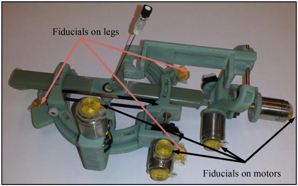
Fiducial markers (Beekley Corporation, Bristol, CT, USA) were attached to the robot on the piezo-motors and on the robot legs. Fig. 9 shows the robot with fiducials. The robot was placed on the shoulder of a human volunteer and images were acquired using the spine coil in the MRI table. The following imaging parameters were used: a) T1 weighted image: SL4, TE 9.1 and TR 500 and b) T2 weighted image: SL4, TE 57 and TR 3300.
Figure 9.
The robot with fiducial markers.
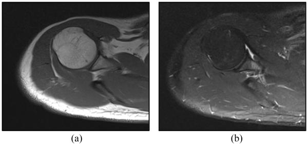
Figures 10(a) and 10(b) show T1 and T2 weighted axial MRI image of the shoulder joint space, while the robot was placed on the shoulder. These images were examined by an interventional radiologist. The radiologist confirmed that the artifacts caused by this shoulder mounted robot are negligible and should not affect the targeting of the joint for contrast injection.
Figure 10.
Axial MRI baseline image obtained by spine coil showing the joint space with robot on the shoulder: (a) T1 weighted image (b) T2 weighted image.
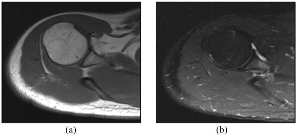
To compare the images with and without the robot on the human subject’s shoulder, the robot was removed from the shoulder and another set of images were taken without the robot on the shoulder. Fig. 11 shows an axial MRI image of the shoulder after removing the robot from the shoulder. Fig. 11(a) shows the MRI image acquired using T1 signal weighting and Fig. 11(b) shows the MRI image acquired using T2 signal weighting. Comparing Fig. 11(a) and 11(b) with Fig. 10(a) and 10(b), respectively, demonstrates that the robot is far enough from the target area and there is no noticeable artifact on the joint space area after attaching the robot to the patient’s shoulder. It shows that the MRI images obtained by the spine coil in the presence of the robot are sufficient for the targeting of the joint space.
Figure 11.
Axial MRI image of human subject’s shoulder after removing the robot: (a) T1 weighted image (b) T2 weighted image.
VI. Conclusions
Mechanical design criteria for a patient mounted robot were discussed and addressed in the prototype design. The clinical workflow for arthrography using the new MRI-compatible robot was presented. Kinematic equations for the robot have been derived. The first prototype was demonstrated and some MRI compatibility experiments were completed to determine the artifacts caused by the motors. The robot design was modified to move the motors away from the targeting area. The experiments proved that the MRI images were not affected by placing the robot on the shoulder of a human volunteer. We also showed that the spine coil of the MRI machine is sufficient for joint space targeting for contrast injection.
VII. Future Work
In future work, an MRI-compatible controller will be developed for the robot. The registration algorithm will be completed and an end-to-end phantom test of the new clinical workflow will be carried out. Our long-term goal is to enable automatically driving a needle and injecting contrast during a real-time MRI sequence for arthrography. The needle driver capability could also be adapted to other interventional MRI procedures. Other enabling technology such as force sensing [9], robot to scanner registration [10], and an MRI-compatible haptic device [11] could also be incorporated to reach these goals.
Footnotes
This research was supported by an internal grant from the Sheikh Zayed Institute, funded by the government of Abu Dhabi, and by NIH grant R01CA172244.
Contributor Information
R. Monfaredi, Sheikh Zayed Institute for Pediatric Surgical Innovation, Children’s National Medical Center, 111 Michigan Ave. DC 20010 USA; Industrial Department, Azad University Sough Tehran Branch, Tehran, Iran
R. Seifabadi, Sheikh Zayed Institute for Pediatric Surgical Innovation, Children’s National Medical Center, 111 Michigan Ave. DC 20010 USA
I. Iordachita, Laboratory for Computational Sensing and Robotics (LCSR), John Hopkins University, 3400 N. Charles St. Baltimore MD 21218 USA.
R. Sze, Sheikh Zayed Institute for Pediatric Surgical Innovation, Children’s National Medical Center, 111 Michigan Ave. DC 20010 USA
N. M. Safdar, Sheikh Zayed Institute for Pediatric Surgical Innovation, Children’s National Medical Center, 111 Michigan Ave. DC 20010 USA
K. Sharma, Sheikh Zayed Institute for Pediatric Surgical Innovation, Children’s National Medical Center, 111 Michigan Ave. DC 20010 USA
S. Fricke, Department of Diagnostic Imaging and Radiology, Children’s National Medical center
A. Krieger, Sheikh Zayed Institute for Pediatric Surgical Innovation, Children’s National Medical Center, 111 Michigan Ave. DC 20010 USA.
K. Cleary, Sheikh Zayed Institute for Pediatric Surgical Innovation, Children’s National Medical Center, 111 Michigan Ave. DC 20010 USA.
REFERENCES
- [1].Lykissas M, Eismann E, Parikh S. Trends in pediatric sports-related and recreation-related Injuries in the United States in the last decade. Journal of Pediatric Orthopedics. 2013;33(8):803–810. doi: 10.1097/BPO.0000000000000099. [DOI] [PubMed] [Google Scholar]
- [2].Walsh C, Hanumara NC, Slocum AH, Shepard JA, Gupta R. A Patient-Mounted, Telerobotic Tool for CT-Guided Percutaneous Interventions. J. of Med. Devices. 2008;2(1):011007.1–011007.10. [Google Scholar]
- [3].Wu FY, Torabi M, Yamadak A, Golden A, Fischer GS, Tuncali K, Frey DD, Walsh C. An MRI Coil-Mounted Multi-Probe Robotic Positioner For Cryoablation; Proceedings of the ASME International Design Engineering Technical Conferences & Computers and Information in Engineering Conference; Portland, Oregon, USA. 2013.pp. 1–9. [Google Scholar]
- [4].Maurin B, Bayle B, Piccin O, Gangloff J, de Mathelin M, Doignon C, Zanne P, Gangi A. A Patient-Mounted Robotic Platform for CT-Scan Guided Procedures. IEEE Transactions on Biomedical Engineering. 2008;55(10):2417–2425. doi: 10.1109/TBME.2008.919882. [DOI] [PubMed] [Google Scholar]
- [5].Hungr N, Fouard C, Robert A, Bricault I, Cinquin P. Interventional Radiology Robot for CT and MRI-guided Percutaneous Interventions. Med Image Comput Comput Assist Interv. 2011;14(1):137–44. doi: 10.1007/978-3-642-23623-5_18. [DOI] [PubMed] [Google Scholar]
- [6].Bricault I, Jouniaux E, Zemiti N, Fouard C, Taillant E, Dorandeu F, Cinquin Ph. A Light Puncture Robot for CT and MRI Interventions. Engineering in Medicine and Biology Magazine,IEEE. 2008;27(3):42–50. doi: 10.1109/EMB.2007.910262. [DOI] [PubMed] [Google Scholar]
- [7].Song SE, Tokuda J, Tuncali K, Yamada A, Torabi M, Hata N. Design Evaluation of a Double Ring RCM Mechanism for Robotic Needle Guidance in MRI-guided Liver Interventions; 2013 IEEE/RSJ International Conference on Intelligent Robots and Systems (IROS); Tokyo, Japan. 2013.pp. 4078–4083. [Google Scholar]
- [8].Monfaredi R, Sze R, Safdar N, Sharma K, Cleary K. Patient Mounted CT and MRI-Compatible Shoulder Arthrography Robot for Needle Guidance in Pediatric Interventional Procedures; The Hamlyn Symposium on Medical Robotics; London, England. 2013.pp. 117–118. [Google Scholar]
- [9].Monfaredi R, Seifabadi R, Fichtinger G, Iordachita I. Design of a Decoupled MRI-compatible Force Sensor Using Fiber Bragg Grating Sensors for Robot-assisted Prostate Interventions; Proc. SPIE 8671, Medical Imaging 2013: Image-Guided Procedures, Robotic Interventions, and Modeling, 867118; Florida, USA. 2013. [Google Scholar]
- [10].Krieger A, Metzger G, Fichtinger G, Atalar E, Whitcomb LL. A Hybrid Method for 6-DOF Tracking of MRI-Compatible Robotic Interventional Devices; Proceedings of IEEE International Conference on Robotics and Automation; Orlando, Florida, USA. 2006.pp. 3844–3849. [Google Scholar]
- [11].Seifabadi R, Iordachita I, Fichtinger G. Design of a teleoperated needle steering system for MRI-guided prostate interventions; IEEE International Conference on Biomedical Robotics and Biomechatronics (BioRob); Rome, Italy. 2012; pp. 793–798. [DOI] [PMC free article] [PubMed] [Google Scholar]


