

Abstract
Although 3D bio-printing technology has great potential in creating complex tissues with multiple cell types and matrices, maintaining the viability of thick tissue construct for tissue growth and maturation after the printing is challenging due to lack of vascular perfusion. Perfused capillary network can be a solution for this issue; however, construction of a complete capillary network at single cell level using the existing technology is nearly impossible due to limitations in time and spatial resolution of the dispensing technology. To address the vascularization issue, we developed a 3D printing method to construct larger (lumen size of ~1mm) fluidic vascular channels and to create adjacent capillary network through a natural maturation process, thus providing a feasible solution to connect the capillary network to the large perfused vascular channels. In our model, microvascular bed was formed in between two large fluidic vessels, and then connected to the vessels by angiogenic sprouting from the large channel edge. Our bio-printing technology has a great potential in engineering vascularized thick tissues and vascular niches, as the vascular channels are simultaneously created while cells and matrices are printed around the channels in desired 3D patterns.
Keywords: 3D bio-printing, capillary, vasculogenesis, angiogenesis, vascular lumen, hydrogel
INTRODUCTION
Due to diffusion limitation (100 – 200 μm for oxygen)6, tissues thicker than a few hundred micrometers have difficulties in survival and proliferation without dense population of vasculatures located within the diffusion limit distance26,46. Building appropriate vascular structure is critical to vitalize thick tissue, and is an important step towards clinical applications of tissue engineering26.
Many approaches have been attempted to solve this problem27. One of the most investigated methods is seeding endothelial cells (ECs) in scaffolds with pre-defined macro- or micro-channels fabricated by free-form manner8–10,16,24,30,31,34,39 or by micro-fabrication technology3,16,20,24,37,40,44,51,55. However, seeding ECs inside the pre-fabricated thick scaffolds is still a very challenging task. In addition, because traditional three-dimensional (3D) free-form fabrication typically involves UV, high temperature or abnormal pH, viable cells cannot be deposited during the fabrication process and have to be seeded later, therefore, greatly limits the ability to design complex tissue structures with multiple cell types. Another approach is to generate pre-vascularized tissue by mixing ECs and mural cells with hydrogels8,22,48,50. After it is implanted into the animal, the vascular remodeling will occur and eventually connect to the host circulation. However, because the cells are simply mixed with the hydrogel, it is difficult to control the spatial organization of the cell-gel structure. In addition, the vascular formation is very limited before implantation and flow through the vasculature has not been achieved.
Recently, 3D bio-printing technologies capable of on-demand control of cells, biomaterial scaffolds have been developed2,12,28,29,33,35,45,52,54. This will allow the creation of complex 3D hydrogel structure and deposition of live cells within the structure at the same time of the bio-printing process. However, construction of a complete capillary network (~10 μm in diameter) at single cell level using current bio-printing technology is nearly impossible due to limitations in time and spatial resolution. Even techniques capable of single cell level patterning still require considerable manufacturing time (from hours to days) for a small piece of tissue at millimeter size, therefore, is incompatible with the live tissue fabrication. Therefore, bio-printing at a lower resolution (~100 μm) is more practical than the ones at single cell level (1–10 μm).
In this study, we developed a 3D printing method to construct larger (lumen size of ~1mm) fluidic vascular channels and to create adjacent capillary network through a maturation process, thus providing a method to connect the capillary network to the large perfused vascular channels. We first developed a 3D printing method demonstrating fluidic vascular channels with a lumen size (diameter) of 0.5–1mm, and ECs and the supporting mural cells can be easily introduced around the vascular channel and allowed to remodel. Microvasculature network was formed by embedding ECs and fibroblasts within the fibrin gel in-between the two vascular channels, and angiogenic sprouting was derived from the larger printed vascular channels to create capillary-vascular channel connection (Fig. 1). The remodeling process is driven by soluble factors, ECMs, and cell-cell interaction between ECs and the supporting cells4,38,53. The bio-printing technology allows the easy embedding of all these components within 3D scaffold at the desired location. Therefore, constructing a larger vascular perfusion channel followed by maturation of the channel and growth of the capillary network represents a feasible approach to address the vascularization issue.
Figure 1.

Schematics of growth and maturation process of the multi-scale vascular system fabricated by using 3D bio-printing technology.
MATERIALS AND METHODS
3D Bio-Printing System
We have developed a bio-printing platform based on the 3D solid freeform fabrication technology. This platform has been used and reported in previous studies 28–30,41,54. The printing system consists of a 3-axis robotic stage, a dispenser array with individually-controlled valve dispensers, material loading units (syringes and tubes connected to dispensers and pneumatic pressure regulators) and an attachable temperature-controlling unit. The liquid-based materials including cell suspensions, soluble growth factors/chemicals, micro-beads suspension, and many types of hydrogel precursors can be dispensed by air pressure during the gate opening of the micro-valve. The volume of dispensing droplet (i.e. drop size) can be adjusted by control of valve opening duration and the air pressure to the fluid pathway. Normal operation allows for continuous dispensing with an actuation frequency of 1 kHz, providing high throughput printing capability. The resolution can be varied systematically by controlling the volume of the dispensed droplets. The minimum resolution of the printing varies with the viscosity of the material. For aqueous materials (e.g. water and cell culture media), the minimum resolution is ~100 μm, and is greater (~200 μm) for viscous materials (e.g. collagen and matrix proteins). A user-friendly software interface facilitates on-demand generation of spatial patterns of the materials in 3D at sub-cellular accuracy with bidirectional reproducibility of 5 μm.
Cell culture and hydrogel preparation
Human umbilical vein endothelial cells (HUVECs) were cultured at 37°C in 5% CO2 in EGM®-2 Endothelial Cell Growth Medium-2 (Lonza; containing hEGF (human recombinant Epidermal Growth Factor), hydrocortisone, GA-1000 (Gentamicin, Amphotericin-B), FBS (fetal bovine seum), VEGF (Vascular Endothelial Growth Factor), hFGF-B (human Fibroblast Growth Factor - Basic with heparin), R3-IGF-1 (Human Recombinant Insulin-like Growth Factor), ascorbic acid, and heparin). Normal human lung fibroblsts (NHLFs) were cultured at 37 °C in 5% CO2 in Dulbecco’s modification of Eagle’s Medium (DMEM) supplemented with 15% Fetal Bovine Serum (FBS) and 1% Penicillin/Streptomycin. Culture media was changed every two days. HUVECs and NHLFs were routinely passaged onto tissue culture flask and were discarded after 8 passages and 12 passages respectively to ensure representation of key characteristics. In order to individually image the capillary formation and endothelial cell sprouting, HUVECs transfected with lentivirus over expressing EGFP (green) and mCherry (red) were separately cultured. GFP-HUVECs were used to create microvascular bed in between fluidic channels. mCherry-HUVECs were seeded on the inner surface of the two larger fluidic channels. NHLFs were not labeled with fluorescent color. Right before cell seeding, cells were harvested using 0.25% Trypsin-EDTA, and then maintained as cell suspensions on ice until ready to be seeded.
Collagen hydrogel precursor (Rat tail, type I, BD Biosciences) was used as a main scaffold material for printing. The collagen precursor from stock was diluted to 3.0 mg/mL and was maintained on ice until ready to be loaded into a syringe (which serves as a printer cartridge) for printing. Gelatin from porcine skin (Sigma-Aldrich) was used as a sacrificial material to create fluidic channels. The concentration of gelatin solution was adjusted to 10%, in which gelatin is reversibly solidifies at room temperature and liquefies at 37°C. To create capillary bed, Fibrinogen (final concentration: 10 mg/mL), thrombin (final concentration: 3U/mL), HUVECs (final cell density: 1×10⁶ cells/mL), and NHLFs (final cell density: 2×10⁶ cells/mL) were prepared and maintained on ice until ready to be deposited.
Defining Printing Parameters
Printing pressure and dispenser valve opening times (pulse duration) are crucial parameters for the proper printing of various biomaterial hydrogel and cells. These parameters were determined based upon the viscosity of the biomaterials being dispensed. The lowest pressure that showed stable dispensing without clogging was used for the printing of collagen and gelatin. As 10% gelatin solution at 37°C is more viscous than collagen precursor, higher pressure was employed for the printing of gelatin compared to collagen. Pressure values in the range of 3.0 – 4.0 psi and 750 μs for valve opening times were used for collagen printing. For gelatin printing, 4.0 – 5.5 psi of pressure and 750 μs of valve opening time were used.
Construction of two fluidic vascular channels with microvascular bed
Through a layer-by-layer approach29,30,54, we created two fluidic vascular channels within a 3D collagen I matrix (3 mg/mL) using 10% gelatin as a sacrificial material (Fig. 2). The collagen precursor was printed on a flow chamber and polymerized by NaHCO3 nebulization This collagen printing step was repeated 5–6 times to fill the bottom half of the flow chamber (Fig. 2, step 1). 10% gelatin, a thermo-reversible hydrogel used as a sacrificial material, was printed in a straight pattern (Fig. 2, step 2). The gelatin solidified within 1~2 minutes when it was exposed to room temperature. The flow chamber was kept in 4°C for 10 minutes to complete gelatin solidification and to provide higher degree of rigidity to gelatin pattern. Fibrinogen, thrombin, HUVECs (GFP-transfected), and NHLFs (kept on ice before use) were quickly mixed, and deposited in between two channels during the fabrication process (Fig. 2, step 3). Once fibrin gelation was completed (~5 min), several layers of collagen were printed on top of the entire structure (Fig. 2, step 4). The whole structure was then incubated for 20–30 minutes to liquefy gelatin and obtain fluidic channels. Then mCherry-transfect HUVECs were injected into the channels in suspension (seeding density: 8 million cells/mL) to be seeded on the inner channel surface and create cell lining (Fig. 2, step 5). Following this step, the flow chamber was connected to a peristaltic dispensing pump and gentle media flow was applied (Fig. 2, step 6). The entire construct was printed on a flow chamber which allows stable, long-term perfusion41,54. Total four needles were installed on a single flow chamber to separately connect two fluidic channels to the perfusion system. The construct was cultured with EGM-2 media flow (10–100 μL/min, <1 dyn/cm2 of shear stress) through the one or two vascular channels for 14 days.
Figure 2.
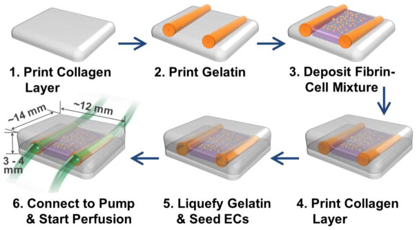
Channel construction and fibrin deposition procedure using 3D bio-printer.
Immunostaining
Following the 14 days of culture, the vasculature samples were fixed with 4% paraformaldehyde. The immunostaining of CD31 marker was performed using Mouse Anti-Human CD31 antibody (Life Technology) and Alexa Fluor 350 Goat Anti-Mouse IgG (H+L) antibody (Life Technology) to visualize the morphology of individual HUVEC that forms capillaries. Each antibody incubation step was followed by 3 washing steps with DPBS, 10 minutes each.
Measurement of Diffusional Permeability
To demonstrate the functional significance of the vascular structures on perfusion, we measured diffusional permeability of the vascular structures and compared with that of control samples. The control samples had same exact structure with the proposed model (Fig. 1 & 2) except that the fibrin-cell mixture was made out of only fibrin and NHLFs, without HUVECs. Thus, there were no capillary formation occurred in the control samples while NHLFs proliferated, produced collagen and filled the structure. The diffusional permeability was assessed by injecting culture media containing 20 μg/mL Alexa Fluor 647-conjugated 10 kDa dextran (Invitrogen) through one of the larger vascular channels. After injection, fluorescence images were captured every two minutes for 10 minutes using a wide-field fluorescent microscope. A diffusional permeability was calculated by quantifying changes of fluorescent intensity over time using the following equation; , where Pd permeability coefficient, I1 is average intensity at an initial time point, I2 is average intensity after delta time (Δt), Ib is background intensity, and d is diameter of the channel 43
RESULTS
Construction of multi-scale vascular network and capillary formation within fibrin
We constructed two fluidic channels with adjacent capillary network within fibrin gel embedded in-between the two channels through 3D bio-printing (Fig. 3). In order to individually recognize the capillary formation occurred within fibrin gel and the endothelial cell sprouting from the larger fluidic channel, HUVECs transfected with GFP (green) and mCherry (red) were separately cultured and used for fibrin gel and fluidic channels, respectively (Fig. 3). GFP-HUVECs were used to create microvascular bed in between fluidic channels (Fig. 4). As shown in Figure 3 and 4, the seeded GFP cells maintained round shape with minimal proliferation until Day 2. Then they began to stretch and formed primary capillary plexus on Day 4. The connections between GFP-HUVECs became denser and more complex over time, accompanying cell proliferation and stretching (Day 4–8). Lumen formation began on Day 8–9, and a uniform and clear lumen structure was developed over the next few days (Fig. 4).
Figure 3.

Two vascular channels and fibrin-cell mixture deposited in between. GFP-HUVECs were embedded within fibrin part for microvascularization. RFP-HUVECs were seeded on the two fluidic channels to form vasculature with mm-scale of lumen size.
Figure 4.
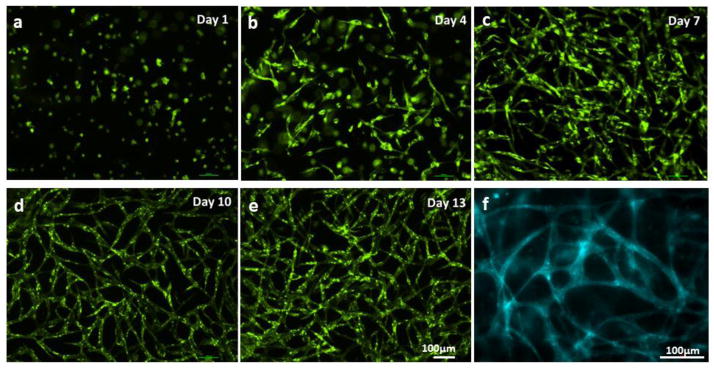
Capillary network formation process. (a–e) GFP-HUVECs first formed plexus structure, then capillaries with lumen were developed. (f) CD31 staining on Day 14.
NHLFs, the supporting mural cells, were not labeled with fluorescent color, thus not shown in the figure. However, general distribution of NHLFs can be identified using wide-field phase contrast microscopy. The NHLFs proliferated rapidly, and filled 50–60% of the entire collagen structure (12 mm × 20 mm × 3 mm) after two weeks of culture. The proliferation and migration rate of NHLFs are far higher than that of HUVECs. HUVECs first formed capillary network within fibrin, then the network became denser and more uniform as HUVECs increase their number within fibrin. After then, the capillaries grew toward the outer collagen space already filled with NHLFs.
The HUVECs began to form tube structure on Day 8–9, and the capillary network became denser, created more branches with lumen (Fig. 3 and 4). The hollow lumen structure of the capillary bed was identified by wide-filed fluorescent microscopy (Fig. 4 and 5a). Tube border and empty hollow space in the middle of capillary tubes were clearly shown in Figure 5a. Images from cryo-sectioned slices confirmed the existence of lumen (Fig. 5b–d). The width of lumen was 10–25 μm in this experiment. CD31 staining of capillaries presented that each tube was enclosed with 2–4 endothelial cells (Fig. 4f). The lumen structure was maintained while they were extending towards the collagen matrix (Fig. 3, magnified inset image).
Figure 5.

HUVECs embedded within fibrin gel formed lumens after 14 days of culture. (a) Wide-field fluorescence microscopy of capillary network. (b–c) Cryo-sectioned slice of capillary network. Luminal structures are clearly presented.
Angiogenic sprouting of ECs sprouting and optimization of media perfusion
We conducted experiments with only large fluidic channels (without fibrin capillary bed) to investigate EC sprouting from the channel edge in various culture conditions. Whereas flow culture condition (shear stress: 10 dyn/cm2) restricted angiogenic sprouting and matrix invasions of ECs, they were actively occurred on the vascular channel edge under static culture condition (Fig. 6). The sprouting initiated on Day 3–4 all over on the channel edge, and extended up to 400 μm on Day 7 (Fig. 6). As the sprouts continued to invade and extend into the collagen matrix, they became longer, contained progressively more cells, and began to branch out. Stereotypical sprouting morphology was observed in these sprouts, presenting thin filopodia-like protrusions at the sprout tip. Although no chemotactic gradient (e.g. gradients of pro-angiogenic factors) was applied within the whole collagen construct, majority of sprouts grew in the orthogonal direction of the channel edge. In most of the cases, cell migration into the collagen matrix was exclusively occurred by angiogenic invasion and sprouting. Single cell migration into the matrix was rarely observed.
Figure 6.

Morphology of HUVECs on the vascular channel edge under static and flow culture condition. Wide-field phase contrast images show the different morphologic changes in dynamic culture (a) and static culture (b) on Day 5. (c, d) The sprouts budded from the channel edge extended over culture time, maintaining filopodia-like protrusion on the tip of the sprouts.
The static culture condition is suitable in this study since the angiogenic sprouting of ECs is required to make connection between the large fluidic channels and the capillary networks formed within fibrin. However, unlike the large channel-only models with limited number of HUVECs, the proposed multi-scale vascular system involves far more cells, and static culture was not able to support the tissue viability more than 3 days. This viability issue can be solved by applying media perfusion through the channel, but we found that fluid shear restricted angiogenesis (Fig. 7a). We compromised the two different culture conditions (static and flow) by applying gentle flow through one of the fluidic channels. 10–100 μL/mL of flow rate was used in this experiment, in which the shear stress was maintained below 1 dyn/cm2. This flow was able to support the viability and lumen formation of the capillary plexus; however, it caused delay on the initiation of angiogenic sprouting for 1–3 days (data not shown).
Figure 7.
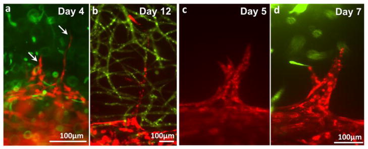
Different types of angiogenic sprouts. (a–b) Thin, long, quick-growing sprouts. (c–d) Wide, slow-growing sprouts.
Sprouting of endothelial cells from the larger fluidic channels
Under the dynamic culture condition (10–100 μL/min of flow rate), the channels successfully supported cell viability and the maturation of microvasculature for 2 weeks. Budding and sprouting of HUVECs from the channel surface began on Day 3–7 (Fig. 7). We observed two different types of cell sprouting which can be roughly categorized into two types. The first type of angiogenesis (Fig. 7a–b) is characterized by thin and long sprouts and earlier initiation of sprouting (Day 3–5). The initial budding of these sprouts involves less than 5 cells and the sprouts quickly invaded into the matrix, extending up to 700 μm on Day 14. The width of the sprouts was 10 – 30 μm. The second type of angiogenic sprouting initiated with more cells at later time point (Day 5–7). The invasion/growth rate of these sprouts is significantly slower than that of thin sprouts. Also, these sprouts often regress when they fail to make contact with capillaries as shown in Figure 7c. The width of the spouts is usually larger than 500 μm. Occasionally, the growing EC sprouts bifurcated or branched out (Fig. 7b–c). The width of bifurcated or branched sprouts became similar to that of parental sprouts 2–3 days after branching. Some of these outreached cell sprouts touched the green capillary network within fibrin and merged with them and develop luminal structure together (Fig. 8). Both the thin sprouts (Fig. 8a–b) and the wide sprouts (Fig. 8c) were able to merge with the capillary within the fibrin gel.
Figure 8.
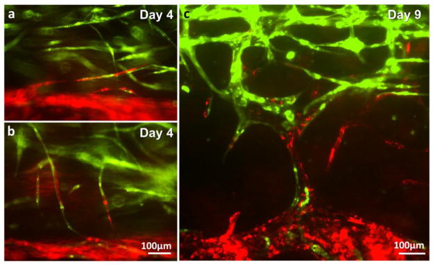
Integration of capillary network (green) and endothelial cells sprouted from the parental vascular channel (red). (a–b) Integration of thin sprouts. (c) Integration of wide sprouts.
Diffusion patterns of dextran in the vascular structures with and without microvascular bed
In order to demonstrate the functional significance of the multi-scale vascular network model on perfusion, 10kDa dextran was injected into the larger vascular channel and the dextran diffusion pattern was observed. In the multi-scale vascular structure, dextran molecules quickly flowed into the microvascular bed through the channel-capillary connection, and then diffused into the tissue (Fig. 9a, top panel). On the other hand, only passive diffusion from the larger channel was observed in the tissue without microvascular bed (Fig. 9a, bottom panel). The diffusional permeability was calculated by quantification of fluorescent intensity (Fig. 9b). The calculation result shows that diffusional permeability is about twice higher in the vascular tissue with capillary network. However, due to the extensive light scattering and the limitation of the imaging techniques in thick tissue as well as the sample variability, the difference is not large enough to be statistically significant.
Figure 9.

Diffusion of 10 kDa Dextran in vascular structures with and without capillary network. (a) Time-lapse fluorescence images of dextran diffusion in structure with capillary network (top panel) and structure without capillary network (bottom panel). RFP-HUVECs were in the larger fluidic channel in both structures. GFP-HUVECs formed capillary network and the capillary network was connected to the larger channel in the structure with capillary network (top). Dextran molecules quickly flowed into the channel-capillary connection in the capillary-containing structure, whereas the molecules stayed in the larger channel in the structure without capillaries.(b) Calculation of diffusional permeability.
DISCUSSION
Our method enables the construction of endothelialized fluidic channels (lumen size of ~1mm), the formation of adjacent capillary network, and consequently the generation of multi-scale vascular network by connecting mm-scale vessels with microvasculatures. The large channels were created using 3D bio-printing technology, and angiogenic sprouting of endothelial cells was derived from the channel edge. The formation of capillary network was achieved by embedding ECs and fibroblasts within fibrin, which allows the self-assembling of ECs into capillary lumens, a process resembles the vasculogenesis. In order to create these two different types of vasculature within single tissue construct, we developed an integrated technique by combining 3D bio-printing technique to control vascular structure for perfusion and the biological self-assembling of ECs, mural cells and matrix. This integrated method allows introducing several critical components into the vascular tissue construct: (1) Proper extracellular matrix that can promote angiogenesis. Fibrin, a natural hydrogel formed from fibrinogen by the protease thrombin, has been shown to induce EC tube formation with mature capillaries surrounded by multiple, polarized ECs8,34,38. (2) Supporting mural cells, fibroblasts (FBs) in this study, are often needed in order to develop and maintain vascular structure stability38,39. These cells provide endogenous growth factors that are essential for vessel formation and remodeling.
Formation of an open vascular lumen is a critical component of the angiogenesis and vasculogenesis process. It is driven by interaction between ECs, mural cells and the extracellular matrices, and is regulated by complex molecular pathways1,5,21,23. We found that the proper combination of cells and matrices is critical for bio-printing of the vascular structure. In this study, we choose collagen gel (3.0 mg/mL) as a main scaffold material because it supports angiogenic sprouting of vascular cells25,40,49 and the structure integrity required for bio-printing. Fibrin gel (10mg/ml) is frequently utilized for in vitro vasculogenesis models8,20, and thus has been chosen to create capillary bed. The choice of cells is also important. We found that NHLFs and HUVECS are able to form robust interconnected vascular lumens; however, if human dermal fibroblasts (HFF-1; ATCC) are used, there was very little capillary lumen formation (data not shown). Interestingly, we found that human dermal microvascular ECs are very limited in their ability to form vascular lumens in this setting, a very surprise finding since they are derived from capillaries. The exact mechanism of what control the differences of these cells in lumen formation is unknown and warrants further studies.
We successfully created a 3D hydrogel structure with two mm-scale channels and fibrin-cell mixture located in-between the channels. Although we used two different types of hydrogel and there were time difference in deposition and gelation, there was no visible gel separation between collagen and fibrin gel. There is a chance that microgap exists at the beginning; however it is likely that these small gaps were filled with actively-proliferating fibroblasts or removed by scaffold remodeling.
We observed that NHLFs proliferated much more actively than HUVECs in 3D culture condition, even though the doubling times of NHLFs and HUVECs in conventional 2D culture condition are similar (15 hours and 17 hours, respectively). It has been reported that EC behaviors are distinct from 2D culture during angiogenesis and vasculogenesis, one example is a decrease in cellproliferation7,11,42. The 3D encapsulation condition may also has a greater influence on HUVECs than NHLFs, as we observed that fibrin-embedded HUVECs maintained round cell shape for 2 days whereas NHLFs expanded its cytoplasm and begun to proliferate from Day 1.
After two weeks of culture, NHLFs occupied 50–60% of the entire volume of the 3D structure. Although large number of fibroblasts embedded in hydrogel generally caused a dramatic contraction/shrinkage of scaffold material18,19, it has not been observed in our study. We postulate that the bio-printing process alter the microstructures of the hydrogel thus change the degree of tissue contraction. This is in consistent with the results from our previous study on skin tissue printing 28. The HUVECs embedded in fibrin formed initial plexus, then capillary network with lumen. The uniformly-distributed network pattern, diameter, and morphological features of the capillaries are comparable to other in vitro microvascular formation researches36,38. There were temporal differences in the initiation of plexus and lumen formation, mainly due to the difference in hydrogel concentrations, hydrogel compositions, and media ingredients.
The existence of flow is critical in inducing angiogenic sprouting from the edge of the large fluidic channels. It has been reported that long-term exposure of endothelium to shear restricts EC proliferation and lowers the metabolic rate32. A complete static condition is ideal for EC sprouting; however, certain level of media perfusion is required to support viability of the thick tissue structure. Gentle flow (10–100μL/mL of flow rate, < 1 dyn/cm2 of shear stress) was used to keep a balance between the tissue viability and angiogenesis. On the other hand, a proper media perfusion is necessary to maintain the stability of the newly formed vascular network. Therefore, to create a stable capillary network which connects flow to the large channel, it is necessary to fine-tune flow rate in a step-wise manner in order to simultaneously control the angiogenic behaviors, tissue survival/maturation and vascular stability. Our platform enables to create a broad span of shear stress and flow pattern, providing opportunities: 1) to investigate flow-relevant behaviors of endothelial cells and vascular tissues; and 2) to obtain a vascular tissue with desired endothelium features.
Active angiogenic EC sprouting was observed at the edge of the large vascular channels. In the experiment with large vessels (without embedding fibrin-cell mixture), EC sprouts grew up to 400 μm for seven days of culture (Fig. 6); however, the sprouts regressed after then (data not shown). Endothelial-coated surface and extracellular matrix (ECM) proteins played a critical role in this early development of EC sprouting6,13,15. However, signals from growth factors or mural cells are necessary to maintain and promote the EC sprouting14,17,38,39. In our proposed vascular tissue model with capillary network, large number of NHLFs secret signaling molecules (e.g. growth factors), maintaining outgrowth of EC sprouts for over two weeks (Fig. 7 & 8). The morphology of sprouts budded from the channel edgeis comparable to other 3D in vitro angiogenesis experiments40,49. The luminal structure on the root and stalk part, thin filopodia-like protrusions at the sprout tip, and branches/bifurcations were observed in our model. However, there are difference in the initiation time point, growth rate, and branching pattern, probably due to the variance in gel concentration and composition, and the difference in culture media ingredients.
Two different types of EC sprouts were presented in this study. The thin and long sprouts are more common than wider sprouts, however there was no particular pattern observed in the occurrences of these sprouts. One explanation will be local irregularities of scaffold material or cell distribution. If a small part of channel edge touches slightly lower concentration of hydrogel or ECs are more densely seeded in a small area, it may cause the wider EC sprouting. There were regressions observed in the wider sprouts when they failed to contact with capillary network. The wider sprouts may require an incorporation of pericytes to avoid the regression and to stabilize the new vessel formation14,15,42,47. It will be interesting to further investigate the differences between these two types of sprouts.
In the dextran diffusion assay, dextran molecules quickly flowed toward microvascular network and showed higher diffusional permeability within a thick tissue structure in comparison to vascular tissue structure without capillaries (Fig. 9). In the vascular tissues with capillaries, the dextran flow pattern revealed architecture of capillary network connected to the larger fluidic channel. The results demonstrated the vascular perfusion capability of our proposed model, as well as clearly confirmed the connection between the large vessel and microvasculatures (Fig. 9a, top panel). The diffusional permeability was calculated based on the fluorescent intensity change in the observation window43. Due to limitations of the current imaging technique on detecting signal from a focal plane of mm-scale thick tissues, signal intensity was acquired by wide field fluorescent imaging. This leads to the signals that come from all depth of the collagen structure instead of just one focal plane. It is considered as a reason why the results had no statistically significant difference between samples with and without capillary network on calculations. Local discrepancies of cell distribution or capillary distribution seem to be also responsible for a wide variation in local signal intensity change. An improved imaging technique capable of measuring the depth-resolved signal intensity in large scale in real time is essential to address the limitations. Mesoscopic fluorescence molecular tomography41,54 capable of imaging depth resolved fluorescent signals in thick 3D structure is currently under development to improve its sensitivity and imaging performance, and can be served as a imaging tool to evaluate an actual filtration of molecules across the endothelium.
In this study, we developed a technique to create perfused in vitro vascular channels with adjacent capillary network using only cells and biological matrices thus allow the occurrence of native vascular remodeling events in the system. Compared to other approaches to microfabricate vascular network that require sophisticated fabrication and assembling steps16,20,40,44,51,55, our approach to create multi-scale vascular network is relatively straightforward. Our bio-printing technology allows the embedding of various components involved in the capillary formation (e.g. supporting cells, soluble factors, and ECMs); therefore, it has a great potential in engineering vascularized thick tissues and vascular niches, as the vascular channels are simultaneously created while cells and matrices are printed around the channels in desired 3D patterns. It can also serve as a unique experimental tool for investigating fundamental vascular biology under 3D dynamic conditions, which is difficult to access either in vivo or in conventional in vitro models. For example, various dynamic culture condition, chemical agents, scaffold components, and different types of mural cells or mesenchymalstem cells can be controlled in our system, thus it provides opportunities to study the influence of individual factors and their synergetic effects on vascular development, maturation and abnormalities.
Acknowledgments
This work was supported by NIHR01HL118245, NSF CBET-1263455, CBET-1350240 and New York Capital Region Research Alliance grant.
Footnotes
CONFLICTS OF INTEREST
Author: Vivian K. Lee, Alison M. Lanzi, Haygan, Ngo, Seung-Schik Yoo, Peter A. Vincent, Guohao Dai declare that they have no conflicts of interest.
ETHICAL STANDARDS
No human studies were carried out by the authors for this article. No animal studies were carried out by the authors for this article.
References
- 1.Adams RH, Alitalo K. Molecular regulation of angiogenesis and lymphangiogenesis. Nat Rev Mol Cell Biol. 2007;8:464–78. doi: 10.1038/nrm2183. [DOI] [PubMed] [Google Scholar]
- 2.Boland T, Mironov V, Gutowska A, Roth Ea, Markwald RR. Cell and organ printing 2: fusion of cell aggregates in three-dimensional gels. Anat Rec A Discov Mol Cell Evol Biol. 2003;272:497–502. doi: 10.1002/ar.a.10059. [DOI] [PubMed] [Google Scholar]
- 3.Borenstein JT, Weinberg ELIJ, Orrick BK, Sundback C, Kaazempur-mofrad MR, Vacanti JP. Microfabrication of Three-Dimensional Engineered Scaffolds. Tissue Eng. 2007;13:1837–1844. doi: 10.1089/ten.2006.0156. [DOI] [PubMed] [Google Scholar]
- 4.Carmeliet P. Blood vessels and nerves: common signals, pathways and diseases. Nature. 2003;4:710–720. doi: 10.1038/nrg1158. [DOI] [PubMed] [Google Scholar]
- 5.Carmeliet P. Angiogenesis in health and disease. Nat Med. 2003;9:653–660. doi: 10.1038/nm0603-653. [DOI] [PubMed] [Google Scholar]
- 6.Carmeliet P, Jain RK. Nature. MACMILLAN MAGAZINES LTD; 2000. Angiogenesis in cancer and other diseases; pp. 249–257. [DOI] [PubMed] [Google Scholar]
- 7.Carmeliet P, Jain RK. Molecular mechanisms and clinical applications of angiogenesis. Nature. 2011;473:298–307. doi: 10.1038/nature10144. [DOI] [PMC free article] [PubMed] [Google Scholar]
- 8.Chen X, et al. Prevascularization of a fibrin-based tissue construct accelerates the formation of functional anastomosis with host vasculature. Tissue Eng Part A. 2009;15:1363–71. doi: 10.1089/ten.tea.2008.0314. [DOI] [PMC free article] [PubMed] [Google Scholar]
- 9.Chiu DT, et al. Patterned deposition of cells and proteins onto surfaces by using three-dimensional microfluidic systems. Proc Natl Acad Sci U S A. 2000;97:2408–2413. doi: 10.1073/pnas.040562297. [DOI] [PMC free article] [PubMed] [Google Scholar]
- 10.Chrobak KM, Potter DR, Tien J. Formation of perfused, functional microvascular tubes in vitro. Microvasc Res. 2006;71:185–196. doi: 10.1016/j.mvr.2006.02.005. [DOI] [PubMed] [Google Scholar]
- 11.Conway EM, Collen D, Carmeliet P. Molecular mechanisms of blood vessel growth. Cardiovasc Res. 2001;49:507–21. doi: 10.1016/s0008-6363(00)00281-9. [DOI] [PubMed] [Google Scholar]
- 12.Cui X, Boland T. Human microvasculature fabrication using thermal inkjet printing technology. Biomaterials Elsevier Ltd. 2009;30:6221–6227. doi: 10.1016/j.biomaterials.2009.07.056. [DOI] [PubMed] [Google Scholar]
- 13.Davis GE, Bayless KJ. An Integrin and Rho GTPase-Dependent Pinocytic Vacuole Mechanism Controls Capillary Lumen Formation in Collagen and Fibrin Matrices. Microcirculation. 2003:27–44. doi: 10.1038/sj.mn.7800175. [DOI] [PubMed] [Google Scholar]
- 14.Davis GE, Koh W, Stratman AN. Mechanisms controlling human endothelial lumen formation and tube assembly in three-dimensional extracellular matrices. Birth Defects Res C Embryo Today. 2007;81:270–85. doi: 10.1002/bdrc.20107. [DOI] [PubMed] [Google Scholar]
- 15.Davis GE, Senger DR. Endothelial Extracellular Matrix: Biosynthesis, Remodeling, and Fufnctions During Vascular Morphogenesis and Neovessel Stabilization. Circ Res. 2005:1093–1107. doi: 10.1161/01.RES.0000191547.64391.e3. [DOI] [PubMed] [Google Scholar]
- 16.Fidkowski C, Kaazempur-Mofrad MR, Borenstein J, Vacanti JP, Langer R, Wang Y. Endothelialized microvasculature based on a biodegradable elastomer. Tissue Eng. 2005;11:302–309. doi: 10.1089/ten.2005.11.302. [DOI] [PubMed] [Google Scholar]
- 17.Ghajar CM, Blevins KS, Hughes CCW, Ph D, George SC, Putnam AJ. Mesenchymal Stem Cells Enhance Angiogenesis Early Matrix Metalloproteinase Upregulation. 2006;12 doi: 10.1089/ten.2006.12.2875. [DOI] [PubMed] [Google Scholar]
- 18.Grinnell F. Fibroblast biology in three-dimensional collagen matrices. Trends Cell Biol. 2003;13:264–269. doi: 10.1016/s0962-8924(03)00057-6. [DOI] [PubMed] [Google Scholar]
- 19.Grinnell F. Fibroblast-collagen-matrix contraction: growth-factor signalling and mechanical loading. Trends Cell Biol. 2000;10:362–5. doi: 10.1016/s0962-8924(00)01802-x. [DOI] [PubMed] [Google Scholar]
- 20.Hsu YH, Moya ML, Abiri P, Hughes CCW, George SC, Lee AP. Full range physiological mass transport control in 3D tissue cultures. Lab Chip. 2013;13:81–9. doi: 10.1039/c2lc40787f. [DOI] [PMC free article] [PubMed] [Google Scholar]
- 21.Iruela-Arispe ML, Davis GE. Cellular and molecular mechanisms of vascular lumen formation. Dev Cell Elsevier Inc. 2009;16:222–31. doi: 10.1016/j.devcel.2009.01.013. [DOI] [PMC free article] [PubMed] [Google Scholar]
- 22.Kachgal S, Putnam AJ. Mesenchymal stem cells from adipose and bone marrow promote angiogenesis via distinct cytokine and protease expression mechanisms. Angiogenesis. 2011;14:47–59. doi: 10.1007/s10456-010-9194-9. [DOI] [PMC free article] [PubMed] [Google Scholar]
- 23.Kamei M, Saunders WB, Bayless KJ, Dye L, Davis GE, Weinstein BM. Endothelial tubes assemble from intracellular vacuoles in vivo. Nature. 2006;442:453–6. doi: 10.1038/nature04923. [DOI] [PubMed] [Google Scholar]
- 24.Khademhosseini A, Langer R, Borenstein J, Vacanti JP. Microscale technologies for tissue engineering and biology. Proc Natl Acad Sci U S A. 2006;103:2480–2487. doi: 10.1073/pnas.0507681102. [DOI] [PMC free article] [PubMed] [Google Scholar]
- 25.Koh W, Stratman AN, Sacharidou A, Davis GE. In vitro three dimensional collagen matrix models of endothelial lumen formation during vasculogenesis and angiogenesis. Methods Enzymol. 2008;443:83–101. doi: 10.1016/S0076-6879(08)02005-3. [DOI] [PubMed] [Google Scholar]
- 26.Langer RS, Vacanti JP. Tissue engineering: the challenges ahead. Sci Am Massachusetts Institute of Technology, USA. 1999;280:86–89. doi: 10.1038/scientificamerican0499-86. [DOI] [PubMed] [Google Scholar]
- 27.Lee V, Dai G. Micro and Nanotechnology in Vascular Regeneration. In: Zhang GL, Webster T, Khademhosseini A, editors. Tissue and Organ Regeneration - Advances in Micro- and Nanotechnology. Pan Stanford Publishing; 2014. [Google Scholar]
- 28.Lee VK, et al. Design and Fabrication of Human Skin by 3D Bioprinting. Tissue Eng Part C Methods. 2013:1–44. doi: 10.1089/ten.tec.2013.0335. [DOI] [PMC free article] [PubMed] [Google Scholar]
- 29.Lee W, et al. Multi-layered culture of human skin fibroblasts and keratinocytes through three-dimensional free form fabrication. Biomaterials Elsevier Ltd. 2009;30:1587–95. doi: 10.1016/j.biomaterials.2008.12.009. [DOI] [PubMed] [Google Scholar]
- 30.Lee W, et al. On-demand three-dimensional freeform fabrication of multi-layered hydrogel scaffold with fluidic channels. Biotechnol Bioeng. 2010;105:1178–1186. doi: 10.1002/bit.22613. [DOI] [PubMed] [Google Scholar]
- 31.Leong MF, et al. Patterned prevascularised tissue constructs by assembly of polyelectrolyte hydrogel fibres. Nat Commun Nature Publishing Group. 2013;4:2353. doi: 10.1038/ncomms3353. [DOI] [PubMed] [Google Scholar]
- 32.Li YSJ, Haga JH, Chien S. Molecular basis of the effects of shear stress on vascular endothelial cells. J Biomech. 2005;38:1949–71. doi: 10.1016/j.jbiomech.2004.09.030. [DOI] [PubMed] [Google Scholar]
- 33.Liu Tsang V, et al. Fabrication of 3D hepatic tissues by additive photo patterning of cellular hydrogels. FASEB J. 2007;21:790–801. doi: 10.1096/fj.06-7117com. [DOI] [PubMed] [Google Scholar]
- 34.Miller JS, et al. Rapid casting of patterned vascular networks for perfusable engineered three-dimensional tissues. Nat Mater Nature Publishing Group. 2012;11:768–74. doi: 10.1038/nmat3357. [DOI] [PMC free article] [PubMed] [Google Scholar]
- 35.Mironov V, Visconti RP, Kasyanov V, Forgacs G, Drake CJ, Markwald RR. Organ printing: tissue spheroids as building blocks. Biomaterials. 2009;30:2164–2174. doi: 10.1016/j.biomaterials.2008.12.084. [DOI] [PMC free article] [PubMed] [Google Scholar]
- 36.Moya ML, Hsu Y, Lee AP, Hughes CCW, George SC. In Vitro Perfused Human Capillary Networks. 2013;19 doi: 10.1089/ten.tec.2012.0430. [DOI] [PMC free article] [PubMed] [Google Scholar]
- 37.Nahmias Y, Schwartz RE, Verfaillie CM, Odde DJ. Laser-Guided Direct Writing for Three-Dimensional Tissue Engineering. Biotechnol Bioeng. 2005;92 doi: 10.1002/bit.20585. [DOI] [PubMed] [Google Scholar]
- 38.Nakatsu MN, et al. Angiogenic sprouting and capillary lumen formation modeled by human umbilical vein endothelial cells (HUVEC) in fibrin gels: the role of fibroblasts and Angiopoietin-1. Microvasc Res. 2003;66:102–112. doi: 10.1016/s0026-2862(03)00045-1. [DOI] [PubMed] [Google Scholar]
- 39.Nakatsu MN, Hughes CCW. An optimized three-dimensional in vitro model for the analysis of angiogenesis. Methods Enzymol. 2008;443:65–82. doi: 10.1016/S0076-6879(08)02004-1. [DOI] [PubMed] [Google Scholar]
- 40.Nguyen DHT, et al. Biomimetic model to reconstitute angiogenic sprouting morphogenesis in vitro. Proc Natl Acad Sci U S A. 2013;110:6712–7. doi: 10.1073/pnas.1221526110. [DOI] [PMC free article] [PubMed] [Google Scholar]
- 41.Ozturk MS, V, Lee K, Zhao L, Dai G, Intes X. Mesoscopic fluorescence molecular tomography of reporter genes in bioprinted thick tissue. J Biomed Opt. 2013;18:100501. doi: 10.1117/1.JBO.18.10.100501. [DOI] [PMC free article] [PubMed] [Google Scholar]
- 42.Potente M, Gerhardt H, Carmeliet P. Basic and Therapeutic Aspects of Angiogenesis. Cell Elsevier Inc. 2011;146:873–887. doi: 10.1016/j.cell.2011.08.039. [DOI] [PubMed] [Google Scholar]
- 43.Price GM, Tien J. Chapter 17: Methods for Forming Human Microvascular Tubes In Vitro and Measuring Their Macromolecular Permeability. In: Khademhosseini A, Suh K-Y, Zourob M, editors. Biological Microarrays: Methods and Protocols, Methods in Molecular Biology. Totowa, NJ: Humana Press; 2011. pp. 281–293. [DOI] [PubMed] [Google Scholar]
- 44.Raghavan S, Nelson CM, PD, Baranski JD, Lim E, Chen CS. Geometrically Controlled Endothelial Tubulogenesis in Micropatterned Gels. Tissue Eng. 2010;16:2255–2263. doi: 10.1089/ten.tea.2009.0584. [DOI] [PMC free article] [PubMed] [Google Scholar]
- 45.Roth Ea, Xu T, Das M, Gregory C, Hickman JJ, Boland T. Inkjet printing for high-throughput cell patterning. Biomaterials. 2004;25:3707–3715. doi: 10.1016/j.biomaterials.2003.10.052. [DOI] [PubMed] [Google Scholar]
- 46.Rouwkema J, Rivron NC, van Blitterswijk CA. Vascularization in tissue engineering. Trends Biotechnol. 2008;26:434–441. doi: 10.1016/j.tibtech.2008.04.009. [DOI] [PubMed] [Google Scholar]
- 47.Saunders WB, et al. Coregulation of vascular tube stabilization by endothelial cell TIMP-2 and pericyte TIMP-3. J Cell Biol. 2006;175:179–91. doi: 10.1083/jcb.200603176. [DOI] [PMC free article] [PubMed] [Google Scholar]
- 48.Sekine H, et al. In vitro fabrication of functional three-dimensional tissues with perfusable blood vessels. Nat Commun Nature Publishing Group. 2013;4:1399. doi: 10.1038/ncomms2406. [DOI] [PMC free article] [PubMed] [Google Scholar]
- 49.Shin Y, et al. In vitro 3D collective sprouting angiogenesis under orchestrated ANG-1 and VEGF gradients. Lab Chip. 2011;11:2175–81. doi: 10.1039/c1lc20039a. [DOI] [PubMed] [Google Scholar]
- 50.Stratman AN, Malotte KM, Mahan RD, Davis MJ, Davis GE. Pericyte recruitment during vasculogenic tube assembly stimulates endothelial basement membrane matrix formation. Blood. 2009;114:5091–101. doi: 10.1182/blood-2009-05-222364. [DOI] [PMC free article] [PubMed] [Google Scholar]
- 51.Wong KHK, Chan JM, Kamm RD, Tien J. Microfluidic models of vascular functions. Annu Rev Biomed Eng. 2012;14:205–30. doi: 10.1146/annurev-bioeng-071811-150052. [DOI] [PubMed] [Google Scholar]
- 52.Xu T, Jin J, Gregory C, Hickman JJJJ, Boland T. Inkjet printing of viable mammalian cells. Biomaterials. 2005;26:93–99. doi: 10.1016/j.biomaterials.2004.04.011. [DOI] [PubMed] [Google Scholar]
- 53.Yancopoulos GD, Davis S, Gale NW, Rudge JS, Wiegand SJ, Holash J. Vascular-specific growth factors and blood vessel formation. Nature. 2000;407 doi: 10.1038/35025215. [DOI] [PubMed] [Google Scholar]
- 54.Zhao L, V, Lee K, Yoo SS, Dai G, Intes X. The integration of 3-D cell printing and mesoscopic fluorescence molecular tomography of vascular constructs within thick hydrogel scaffolds. Biomaterials. 2012;33:5325–5332. doi: 10.1016/j.biomaterials.2012.04.004. [DOI] [PMC free article] [PubMed] [Google Scholar]
- 55.Zheng Y, et al. In vitro microvessels for the study of angiogenesis and thrombosis. Proc Natl Acad Sci U S A. 2012;109:9342–7. doi: 10.1073/pnas.1201240109. [DOI] [PMC free article] [PubMed] [Google Scholar]