Abstract
This tutorial outlines the details of the AOCMF image-based classification system for fractures of the mandibular arch (i.e. the non-condylar mandible) at the precision level 3. It is the logical expansion of the fracture allocation to topographic mandibular sites outlined in level 2, and is based on three-dimensional (3D) imaging techniques/computed tomography (CT)/cone beam CT). Level 3 allows an anatomical description of the individual conditions of the mandibular arch such as the preinjury dental state and the degree of alveolar atrophy. Trauma sequelae are then addressed: (1) tooth injuries and periodontal trauma, (2) fracture involvement of the alveolar process, (3) the degree of fracture fragmentation in three categories (none, minor, and major), and (4) the presence of bone loss. The grading of fragmentation needs a 3D evaluation of the fracture area, allowing visualization of the outer and inner mandibular cortices. To document these fracture features beyond topography the alphanumeric codes are supplied with distinctive appendices. This level 3 tutorial is accompanied by a brief survey of the peculiarities of the edentulous atrophic mandible. Illustrations and a few case examples serve as instruction and reference to improve the understanding and application of the presented features.
Keywords: mandible, fracture classification, dentition, degrees of alveolar atrophy, fracture morphology
Mandibular fractures can be classified under various aspects, such as location, type, completeness, number, and course of fracture lines. Characterization by the anatomic sites involved is commonly the initial stage in the classification process. The allocation of fractures to definite topographical regions of the mandible is the subject of the mandible level 2 tutorial article.1
This level 3 system starts out with refinements in recording the oral conditions: the preinjury dentition status and the degree of alveolar atrophy in toothless zones or the overall edentulous mandible. This is followed by a description of the trauma sequelae with a focus on items going beyond the pure topographical allocation of fractures: (1) tooth injuries and periodontal trauma, (2) alveolar process fractures, (3) fragmentation as one aspect of fracture morphology, and (4) bone loss.
This article provides the background knowledge for the level 3 classification for mandibular fractures including dentition and imaging anatomy.
This tutorial provides rules and illustrations how to make the appropriate fracture diagnosis and generate the associated coding. Case examples with clinical imaging are presented to illustrate the practical application of this system. A brief discussion with a literature review of fracture features beyond anatomic location is concluding this level 3 proposal for the non-condylar mandible. The level 3 classification of condylar process fractures is presented as a subsequent tutorial.2
Anatomical Considerations and Diagnostic Imaging
Symphysis/Parasymphysis
The symphysis/parasymphysis region is the single central unit of the mandibular arch. Its lateral edges are determined by the roots of the lower canines and thus this region matches with the intercanine bone portion. For the purpose of this classification, we will refer to it as the symphysis region.
Outer and Inner Surface of the Mandible
While it is easy to examine the outer surface of the mandible, the medial or inner surface anatomy of the mandible is not amenable to detailed analysis in conventional or panoramic radiographs (Fig. 1). To evaluate the degree of fragmentation or the occurrence of sagittal fracture lines it is indispensable, to examine the inner side of the mandibular arch and the ramus using high performance helical computed tomography (CT) scanners or cone beam CT systems in sort of a ‘horse shoeing’ view. The imaging requirements for this classification are discussed in a companion article in this issue.3
Figure 1.
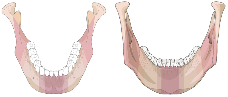
Topography of anatomic regions and transitional zones on outer surface and inner (lingual) aspect of the mandible. Rear view of the mandible (‘horse shoeing view’) as a new imaging option—in conjunction with the outer surface view scrutinizing the posterior aspect for fracture lines facilitates the identification of sagittal fractures.
Level 3 Mandible Fracture Classification System
The level 3 system focuses on the fracture morphology within the symphysis (S), body (B), and angle/ramus (A) anatomical regions of the mandible. While a detailed classification system for condylar process fractures is presented by Neff et al,2 fractures of the coronoid process are not further described beyond their identification in the level 2 system.1
The level 3 system has two main purposes as given below:
Refine basic information on the anatomical properties of the mandible by cataloguing the dentition with permanent teeth and/or the degree of alveolar atrophy after tooth loss, and
Refine the characteristics of the fractures beyond topography by recording tooth injuries and periodontal trauma, indicating the range of alveolar process fractures, quantifying fragmentation on a three-grade ordinal scale and identifying bone loss.
Dentition
The immediate posttraumatic dentition status, including dental and periodontal injuries, requires reliable and meticulous assessment for therapeutic management and insurance-related considerations. As a basis for the subsequent detailed documentation of trauma sequelae, the preinjury dental status is described for the upper and lower jaws recording the missing teeth individually.
The FDI (Fédération Dentaire Internationale) tooth numbering formula (adapted by the World Health Organization) for permanent teeth is used to register the dental status (Fig. 2). In the FDI scheme each tooth is referred to by a two digit number. The first digit refers to the quadrants defined as left (3) and right (4) mandible, respectively (note the digits 1 and 2 refer to the right and left maxilla, respectively). The second digit designates the tooth order starting with number 1 from the midline and ending with number 8 for the third molar. For example, a mandibular left canine is numbered 33, and a mandibular right first molar has the two digit code 46. A correspondence with the tooth numbering formula of the ADA (American Dental Association) is presented in Fig. 2.
Figure 2.
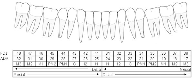
Lower dentition, FDI dental formula, ADA tooth numbering, and tooth acronyms. Note: FDI (Fédération Dentaire Internationale) tooth numbering formula (adapted by WHO) for permanent teeth is referred to by a two-digit number, the first one for the quadrant and the second for the tooth order from mesial to distal. In the tooth numbering formula of the ADA (American Dental Association) the teeth are marked with consecutive numbers following a clockwise order beginning with the maxillary right third molar (1) and continuing to the mandibular right third molar (32). Individual teeth or tooth groups are often given an acronym: “I” stands for incisors, “C” for canine, “PM” for premolar, and “M” for molar. To avoid confusion two terms used conventionally in the dental nomenclature merit clarification: mesial: means toward the midline; distal: means away from the midline. It is to be noted that in surgical terminology distal is the antonym of proximal and means “away from the center”, which is towards the midline in case of the mandible. Preinjury dentition status: Empty tooth sockets originating before the actual trauma will show different stages of bone healing depending on the time period since tooth loss.
In this tutorial, only the lower dentition is addressed independently from bony fractures within the mandibular B and S regions; the upper dentition is presented in the tutorial article for level 3 midface.4
Edentulism: Degree of Mandibular Atrophy
Overtime the alveolar bone of any edentulous portion of the mandible will react with progressive vertical atrophy. In extreme cases, with complete edentulism only the basis of mandible will remain; this situation which is often coined as “pencil bone” condition, which is the most severe form of atrophy. The reduction of the vertical height is confined to the mandibular body regions and the symphysis. In case of partial or complete edentulism four major stages of atrophy in terms of residual vertical bone height are classified according to Luhr et al5 as follows:
0 = No atrophy, original height vertical height > 20 mm
1 = Mild atrophy vertical height > 15 to 20 mm (Luhr Class I)
2 = Moderate atrophy vertical height > 10 to 15 mm (Luhr Class II)
3 = Severe atrophy vertical height ≤ 10 mm (Luhr Class III)
The degree of vertical atrophy is specified separately for the body regions (left and right) and the symphysis (Fig. 3).
Figure 3.
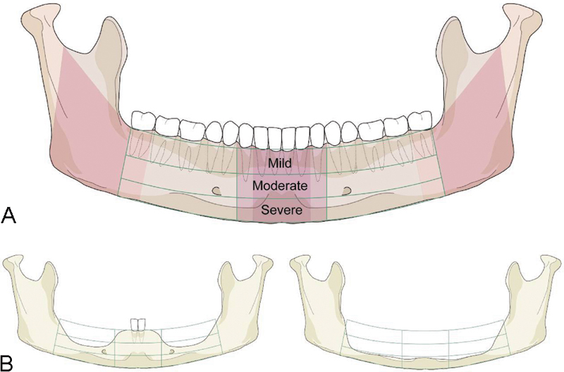
Illustration of mandibular edentulism and atrophy. (A) "Atrophy grid" superimposed on a fully dentulous mandible with permanent teeth. The mandibular body regions, the para–symphsis and the transitional zones depicted as vertical sectors are maintained unchanged. To allocate the fractures to a topographical site the borderlines/frontiers of the region are transferred to the edentulous situation. (B) Left side: Moderate level of atrophy (code 2) on both the body regions, but no atrophy (code 0) in the parasymphysis. Right side: Severe level of atrophy (code 3) over the whole arch of the edentulous mandible ("pencil bone").
In the partially edentulous mandible the bony atrophy principally can take the same form as in complete edentulism, though commonly the vertical atrophy is not as accentuated adjacent to remaining teeth or in tooth gaps. Bony atrophy in partial edentulism is recorded checking the plausibility with the residual tooth pattern.
Tooth Injuries/Periodontal Trauma
With account for the preinjury dentition, the current dental hard tissue and periodontal injuries are documented separately for each involved tooth.
The occurrence of tooth injuries (i.e., tooth loosening, crown and/or root fractures) or tooth loss (tooth avulsion/missing tooth) is recorded6:
Tooth avulsion/tooth loss/missing teeth: The tooth is completely luxated out of its socket. Radiographs show an empty socket.
Crown and/or root fractures: These injuries include enamel fractures (confined to the enamel), enamel–dentin–pulp fractures (substantial loss of tooth substance), crown–root fractures (involving both the coronal and intra-alveolar parts of the tooth) and root fractures (only within the intra-alveolar part).
Tooth loosening: Without displacement, the only sign and symptom of tooth loosening is a marked tenderness to percussion and “a sore tooth.” On radiographs, the injured tooth is in its normal position in the socket, however a loosening can be indirectly assessed by widening of the periodontal spaces mesially or distally. When displaced, the tooth suffers partial axial displacement out of its socket (extrusion).
If there is suspicion for tooth injuries or loss, the nature of which cannot be further specified (e.g., due to imaging shortages), these are classified under the category “undetermined.”
Fracture Involvement of the Alveolar Process
The terms “alveolar fracture,” “alveolar process fracture,” or “alveolar ridge fracture” are used synonymously. A dental alveolus is a tooth socket, the alveolar process is the upper bone portion of the mandibular arch component closely surrounding and supporting the teeth and consisting of several sockets in a continuous row.
An alveolar process fracture is defined as a fracture segment that is bordered between two distinct vertical fracture lines at variable distance from each other and by an interconnecting horizontal fracture line running through the apical base (Fig. 4A, B). Alveolar process fractures are documented by indicating the FDI number(s) of the involved tooth (or teeth), thus providing information about the location and extent of the fracture. No distinction of the exact course of the vertical fracture line directly through a tooth socket or through its mesio- or disto-approximal wall is made.
Figure 4.
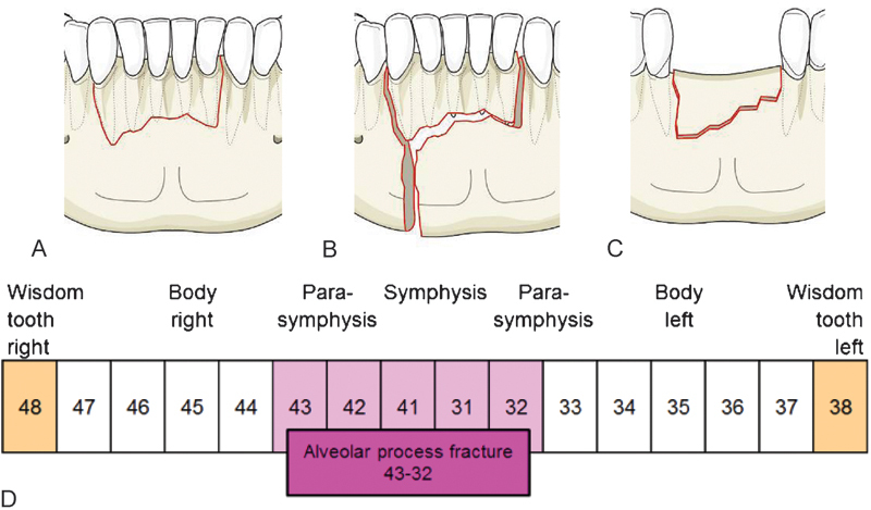
Variations of an anterior alveolar process fracture. Dentoalveolar fracture: Any fracture that is limited to the tooth-bearing area of the mandible. (A) Isolated alveolar process fracture: The nondisplaced fracture block is containing the teeth 43, 42, 41, 31, and 32. (B) Fracture combination: A vertical fracture line in the interdental space 44/43 spreads over the full vertical height of the mandible and delineates the vertical margin of an alveolar process fracture. Both fractures are independently documented. (C) Isolated fracture of an edentulous alveolar ridge: Edentulous portion extending from 42 to 32 pretending the missing teeth were still there. (D) Schematic representation of the alveolar process in the mandible by boxes with the FDI tooth numbers. An alveolar process fracture ranging from 43 to 32 is marked in the schematic bar. In the AOCOIAC classification software program7 the involved teeth or tooth sockets, respectively, can be ticked.
In case an edentulous zone of the alveolar process is entangled by a block-like fracture (Fig. 4 C) the vertical boundaries are indicated pretending as if the teeth were still present. Alveolar fractures are recorded separately from fractures of the basal bone of the mandible.
Fracture Morphology—Fragmentation—Intermediate Fragments
The severity of a fracture can be characterized by the grade and diversity of the bony separation into fragments or the so called fragmentation. The term “fragmentation” is often taken as a synonym to “comminution” or shattering of the bone into pieces. In this context, fragmentation is used as a generic term referring to the appearance, pattern, and the attributes of one or more fracture lines at a given fracture site.
Aside from the two main fragments which result from a single fracture line so-called “intermediate fragments” may be present, which are the product of two or more fracture lines, either interconnected or in close proximity to each other. Consequently, intermediate fragments vary in size from small particles to large pieces, multitude and spatial arrangement.
The crown of a premolar serves as yardstick to approximate the size of the intermediate fragments in the three-dimensions to be independent of differing magnification factors in imaging if exact volumetric measurements were applied. The threshold between, minute' fragments, negligible to be counted in the grading of fragmentation and, small' fragments, relevant for the grading is indeed the crown of a premolar.
The degree of fragmentation at any fracture site within the A, B, and S regions is indicated by one of three categories: no fragmentation (grade 0), minor fragmentation (grade 1), or major fragmentation (grade 2).
However, the regions differ in their vertical extent. Fragmentation within the B and S regions relates to the size of fragments and involvement over the full vertical height of the mandibular arch (Fig. 5). Fragmentation within the A region refers to an increased vertical range above the plane of the alveolar process with potential involvement of the mandibular angle/ramus over its entire height from the inferior border ascending up to the sigmoid notch.
Figure 5.
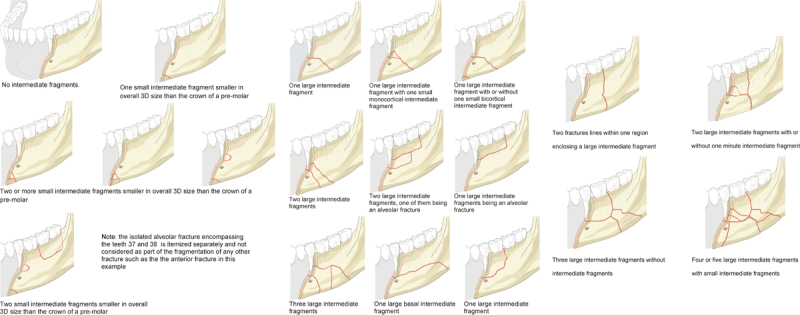
Fragmentation grading in region B and S: 0 = No fragmentation - Definition: None or any number of “minute” intermediate fragment(s) smaller in size than the crown of a pre-molar in any of the three dimensions. Location–limited to the margins or the direct vicinity of the fracture line. Caveat: Fragmentation caused by a multitude of “minute” intermediate fragments involving a segmental zone over a wide range or the full vertical height of the mandibular arch is rated as grade 1 or grade 2, 8 respectively.Fragmentation grading in region B and S: 1 = Minor fragmentation - Definition: One or more intermediate fragment(s) larger in overall 3D size than the crown of a pre-molar (i.e. small or large) and independent of their location, however not involving the full vertical height of the mandibular arch (= region B and/or S). Minute intermediate fragments become relevant for classifying if they occupy a major zone ranging half-way or more over the vertical height of the mandibular arch.Fragmentation grading in region B and S: 2 = Major fragmentation - Definition: One or more small or large intermediate fragment(s) independent of their location at the upper or lower border, but involving the full height of the mandibular arch. This category includes fractures commonly referred to as “comminuted”.
The following rules apply for regions B and S (Fig. 5):
Grade 0: Corresponds to a single fracture line without or with minute intermediate fragments accompanying its course. Such fragments must be limited to the margins directly adjacent to the fracture line. It must be understood that pulverization of wide ranging portions of the mandible does not fulfill the grade 0 criteria, though there are just powder-sized and tiny fragments.
Grade 1: Stands for small intermediate fragments in a zonal distribution not involving the full height of the mandible. This zone can be located in the basal compartment of the mandibular arch or in the alveolar process division.
Grade 2: Classifies a fracture with small or larger intermediate fragments involving the full vertical height of the mandibular arch.
Two independent vertical fracture lines over the full height of the mandible located within the same region (i.e., a unilateral double fracture) are documented as grade 2 fragmentation, since the two lines demarcate one large intermediate fragment.
The following rules apply for region A (Fig. 6):
Figure 6.
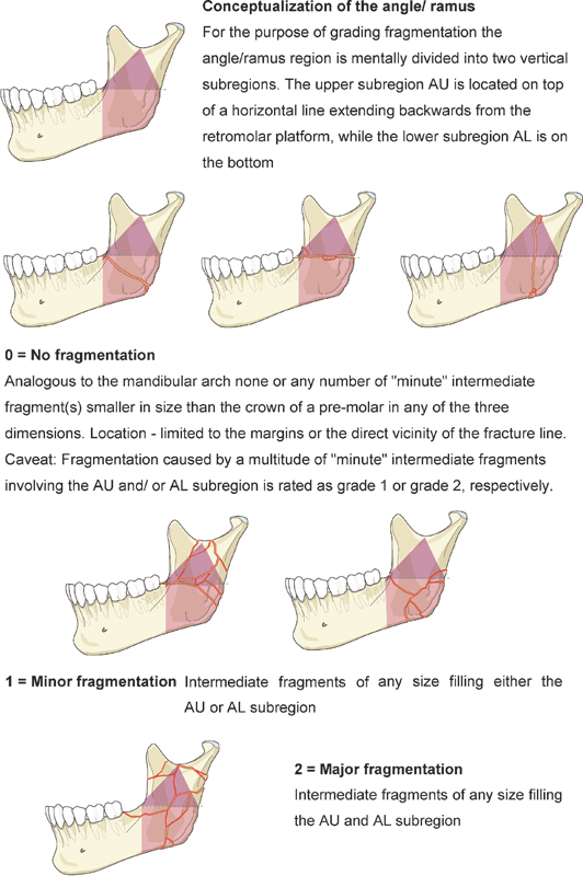
Fragmentation grading in the angle/ramus region.
The angle ramus region is divided by a horizontal line running backward from the retromolar platform, resulting in an upper subregion (AU) and a lower subregion (AL).
Grade 0: It is identical with the grading for region B and S. It should be noted that the pathways of a single “nonfragmented” fracture line through region A are subject to much more variation than in the mandibular arch. A fracture line may travel in a horizontal, oblique, curved, or vertical fashion at variable height or different sagittal levels.
Grade 1: It describes multiple fracture lines spreading out either in subregion AU or in subregion AL. The composition of these fracture zones out of minute small or large-sized intermediate fragments plays a subordinate role. The key criterion is the concentration to the upper or lower topographical subregion.
Grade 2: It classifies multiple fractures distributed over the entire region A (i.e., both subregions AU and AL = total disintegration) independent of the size of the intermediate segments. Attention should be given to the fact that any multifragmented fracture localized in the upper subregion usually involves the base of the condylar and/or the coronoid process. Therefore, such a fracture of either process needs to be documented in conjunction with a grade-1 AU fracture type or a grade-2 A fracture.
In the assessment of fragmentation both the outer/lateral surface and the inner/medial surface must be examined. The highest degree of fragmentation encountered on either side of the mandible is the one single determinant that matters for the classification.
When a (nonconfined) fracture is located over two or several adjacent regions,1 the degree of fragmentation is determined in each region.
Bone Loss/Defect Fracture
Traumatic bone loss in a defect fracture is characterized by a deficit of the original bone mass at the fracture site. Traumatic bone loss must be distinguished from bone atrophy.
Missing bone in any of the mandibular regions may have different functional implications, for example, loss of structural support or tooth loss, in relation to the lost amount and its location. However, in this classification the only determinant for the presence of a bone loss are actual osseous deficiencies due to trauma that are recognizable in the imaging assessment. The dimension and the location of such an osseous deficiency do not really matter, although a defect fracture is commonly associated with discontinuity in the basal mandibular compartment.
Displacement
At present no attempt is made here to classify displacement based on an imaging analysis alone, though it is acknowledged as a paramount descriptor of fracture morphology. The clinically relevant parameter of malocclusion, however, should be documented in the patient charts following clinical examination. Fracture displacement is a salient feature in the system proposed for condylar process fractures by our group.2
Fracture Documentation and Coding
Fractures are coded by letters for their location representing the involved mandibular regions1 from the right side to the left side (P = condylar process; C = coronoid process; A = angle/ramus; B = body; and S = symphysis). At the precision level 3 the dentition status and level of mandibular atrophy are part of the documentation process, even though, they are not entered in the fracture code.
The fragmentation code (0, 1, or 2) is appended following the respective region letter. Bone loss is indicated with the small letter “d” (as “defect”), and the presence of alveolar fractures is coded with the small letter “a.” The level 3 system for condylar process fractures is equipped with coding details of its own which are explained in a subsequent tutorial.2
Case Examples
The following series of three clinical imaging case examples illustrates the coding of fragmentation: grade 0 in a fracture within the symphysis region (Fig. 7); grade 1 in a symphysis fracture associated with an alveolar process fracture (Fig. 8); grade 2 in a fracture predominantly located within the body region with an extension into the symphysis region (i.e., a nonconfined body fracture) (Fig. 9). A case collection can be found in an appendix8 as an electronic supplement of this special issue (www.aocmf.org/classification).
Figure 7.
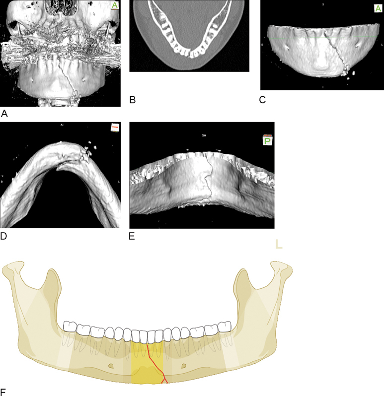
Symphysis fracture of grade 0 fragmentation. (A–E) Imaging: CT scans, 3D reformatted overview, axial slice to identify tooth roots, 3D reformations in detail: Anterior view, basal view, lingual view. Narrative description: Oblique parasymphyseal fracture on the outer surface beginning in the midline interdentally between middle incisors runs downwards to the left and ends at the inferior mandibular border without crossing the anterior transition zone. On the basal and lingual side jagged fracture course indicating a fracture in the frontal plane. (F) Code Level 3: 91 S0. This case example CMTR-91-001 is made available electronically for viewing using the AOCOIAC software at www.aocmf.org/classification.
Figure 8.
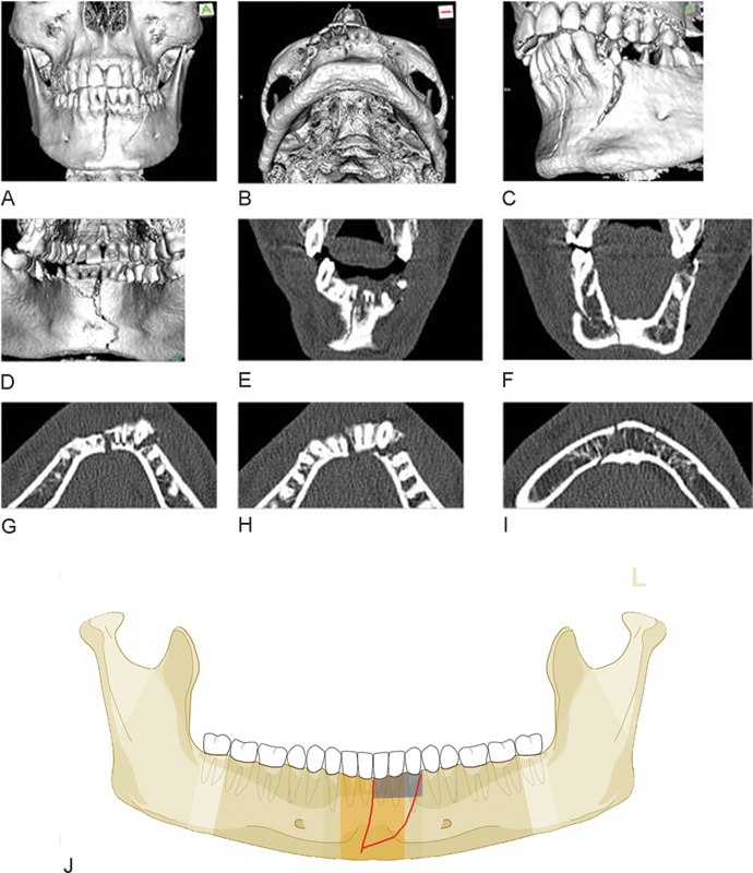
Two fracture lines or one line in conjunction with alveolar process fracture. (A–I) Imaging: CT scans 3D reformatted overviews frontal, basal and in details (oblique left, lingual view); frontal and axial slices. Narrative description: On the outer surface two fracture lines can be identified: a vertical midline fracture and an oblique fracture line between the premolar region on the left and the mental protuberance or the supramental groove, respectively. From the lingual aspect only one fracture line is visible, which extends in a curvilinear course over the full vertical height of the symphyseal region. There is a second through-shaped fracture line embracing the alveolar process 31, 32, 33. The frontal CT scan slices confirm the presence of a single continuous fracture line over the full height of the mandible only. The axial CT scan slices reveal a large wedge-shaped intermediate fragment which involves both cortices at the level of the alveolar process and tapers into a monocortical layer along the outer surface towards its inferior tip. The outlines of the fracture do not coincide with an alveolar process fracture. The configuration corresponds to a fragmentation grade 1. (J) Code level 3: 91 S1a. This case example CMTR-91-026 is made available electronically for viewing using the AOCOIAC software at www.aocmf.org/classification.
Figure 9.
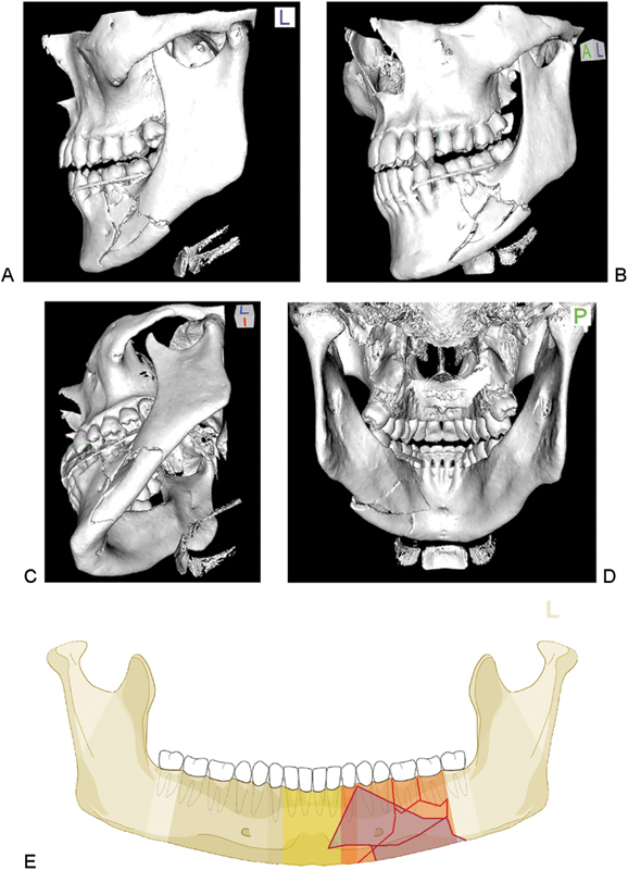
Body fracture of grade 2 fragmentation extending into the symphysis. (A–D) Imaging: CT scans 3D reformatted overviews lateral, anterolateral, laterobasal, and lingual. Narrative description: A look from the outer surface shows multiple large-sized intermediate fragments confined to the mandibular body on the left in its full vertical height. The inspection of the inner aspect exhibits that the anterior tip of a large rhomboid intermediate fragment extends into the symphysis (below 32) (see shaded fragments in illustration below showing fracture pattern on lingual side, which is crucial for to code level 3). The fragmentation the body region is grade 2 and in the symphysis grade 1. (E) Code Level 3: 91 S1-B2. This case example CMTR-91-027 is made available electronically for viewing using the AOCOIAC software at www.aocmf.org/classification.
Discussion
Beyond topographical allocation previous classification attempts for mandibular fractures (see full review in companion article1) have referred to numerous features and categories or combinations thereof (Table 1). These variables have often been used to compose fracture formulas such as FLOSA9 or similar acronyms such as FTLDOSIA10 or the FLOSID taxonomy11 (F= fracture type, T = teeth, L = location, D = displacement, O = occlusion, S = soft-tissue involvement, I = infection, and A = associated fractures). The FLOSID taxonomy and variable combinations thereof were implemented into mandibular injury or facial fracture severity scores.12 13 14
Table 1. Review of diagnostic features considered in mandibular injury classification systems.
| Diagnostic features | References |
|---|---|
| Completeness of fracture lines—incomplete (greenstick) or complete discontinuity of the bone | 19 20 25 26 |
| Number of fractures per mandible—single, double, triple, etc., plural, multiple or multifocal | 9 10 12 13 14 20 25 26 27 28 29 30 31 |
| Distribution or the fracture pattern over the whole extent of the mandible—unilateral, bilateral | 9 10 12 14 20 26 |
| Direction of blow/impact—direct, indirect | 20 25 32 |
| Mechanism—bending, burst, avulsion | 19 |
| Dentition/condition of teeth | 10 25 30 33 34 |
| Structural weakness/predilection sites pathologic erosion (e.g., cysts, metastases, tumors, osteoradionecrosis, bisphosphonate/Anti-resorptive medication induced osteonecrosis, systemic bone disorders, etc.) | 28 |
| Presence or absence of serviceable teeth in the fragments for treatment with arch bars/splints | 25 35 |
| Fracture type, variety of fracture—simple, complex, comminuted, multifragmentation at one fracture site | 9 10 12 13 20 24 30 31 |
| Fracture line course or shape of fractured area—transverse, oblique; butterfly or oblique shape | 19 |
| Bone defect/loss | 9 10 14 24 31 |
| Deviation | 10 |
| Displacement | 10 11 12 13 14 20 24 27 30 31 |
| Stability—stable, unstable mobile, nonmobile, impacted, telescoping | 10 19 25 27 31 36 37 |
| Direction of fracture and potential/favorableness to displacement by muscle pull | 19 20 27 29 36 38 |
| Occlusion—no disturbance, malocclusion, toothlessness | 9 10 |
| Dislocation—condylar head entirely out of glenoid fossa | 24 37 38 |
| Soft tissue involvement—intra- and/or extraorally wound communication, compound, soft-tissue defect; complicated fractures by vessel or nerve damage | 9 10 11 12 20 25 |
| Infection | 10 11 |
| Associated fractures | 9 10 12 14 |
In this level 3 classification proposal for mandibular fractures consideration is given to a few clinically relevant items, with two of them serving for a refined description of the preinjury condition of the mandible.
The applied scheme is purposely limited to record the presence or absence of teeth. It omits dental details such as fillings, crown, and bridgework or dental pathology (apical, cysts, parodontopathies, periodontal bone loss/defects, tooth mobility, nonreactivity to vitality testing) since these conditions go beyond pure radiographic description and require clinical assessment. Up till now enosseous dental implants remain unconsidered but the insertion sites certainly play an important role for an increased vulnerability in mandibular trauma.
Atrophy is typically more advanced laterally in the mandibular body and angle regions than in the symphysis region.15 The description of the localization and degree of atrophy separately for each tooth or region allows identification of mandibles that are susceptible to different fracture patterns. There are several classification proposals in prosthodontic dentistry and implantology to quantify the degree of atrophy in edentulous jaws.15 16 17 18 For this level 3 the well-known Luhr classification5 of atrophic mandibles was adopted. In addition, to the atrophy process in vertical height the bone dimensions of edentulous portions of the mandible decrease in a transverse or horizontal direction. It can be assumed that the bony diminution in all three-dimensions is predisposing for fractures. Thus, in contrast to the dentate mandible the body region (premolar area, mental foramen) is a typical predilection site for fractures in the atrophic mandible.
The broad category of tooth injuries advocated here can be broken down into a manifold of subcategories (e.g., tooth loosening crown, crown–root, and root fractures vertical height and horizontal crown or root fractures at different levels, infractures, extrusion, lateral luxation, etc.). A precise distinction may become necessary for individual dental or implant/prosthetic treatment decisions, but surpasses the needs of a surgically oriented CMF fracture classification. To determine the degree of tooth loosening by indirect radiographic criteria is more likely to be erroneous than by simple clinical testing. In CT scans crown or root fractures are often clouded by the metallic artifacts resulting from bridge and crown work. Tooth avulsion, tooth loss or missing teeth can be easily recognized, since all types of radiographs show an empty socket.
The presence of teeth in the fracture line is often debated as an important criterion in the treatment of mandibular angle fractures, though it has never been a classification item in the past. Certainly, it is far more convenient to assess the dental status and dental or periodontal injuries in panoramic radiographs or Cone beam CTs than in helical CT scans. However, the last two allow for the same accuracy at least if evaluated carefully in an appropriate multiplanar analysis.
The documentation of block fractures of the alveolar process in addition to dental trauma and tooth loss conveys topographical information that has not been supplied in the level 2 system. In a sense this introduces the region above the basal bone compartment in the mandibular arch, well known from the first classification proposals.19 20 In alveolar process fractures the tooth roots may be unaffected and enclosed in the bone block or exposed at its base toward the fracture line. They may also be fractured themselves and located in the fracture line or either one of the upper or lower bone fragments.
The degree of fragmentation in practice varies on a continuous scale from none to severe, and can be fully assessed only with the benefit of 3D imaging technologies.
Fragmentation refers to the breaking up of a fracture zone into pieces, or to the composition of fragments. So fragmentation represents an umbrella-term encompassing several degrees of fracture disruption that may be located in one or several adjoining regions. Fragmentation must be distinguished from the fracture pattern, which refers to the distribution and number of fractures over the entire mandible (unilateral, bilateral, single, double, triple, etc.). The vocabulary to describe the degree of fragmentation from existing classifications sounds familiar: simple, complex, comminuted, and multifragmentary. These attributes however are imprecise or vaguely defined. The word “simple” is typically confused with “single” or “easy to treat,” what may not necessarily be identical. The degree of fragmentation is commonly assessed by subjective clinical judgment. A more objective method of evaluation is applied in long bone fractures according to the number and extent of fragments21: a complex fracture consists of one or more intermediate fragment(s), which are supposed to have no contact to the main fragments after reduction; multifragmentary is referred to fractures with more than one fracture line resulting in three or more pieces.
In the mandible, the term “simple” is suggested to describe a linear one-line fracture resulting in two main fragments while “complex” fractures comprise at least two fracture lines, including basal triangle, segmental, comminuted, and defect fractures.22 Our objective was to devise an appropriate fragmentation scale under geometric-structural aspects. The size, number, and extent of fragments over the vertical height at the inner and outer cortex of the mandibular arch were considered as well as the peculiarities of the distribution of fracture in the angle/ramus region. The size of a crown of the lower premolars was utilized as an easily obtainable measure for sizing the fragments in a 3D manner.
There may be differences in the degree of fragmentation between the outer and the inner surface of the mandible. The surface with the most pronounced degree of fragmentation is of clinical relevance. The 3D imaging techniques offer an easy access to viewing of the inner mandibular surface and thus must complement the panorama-style documentation for advanced fracture classification such as this level 3 system. The two-aspect 3D image analysis also offers the possibility to identify sagittal fracture courses23 with an extent into adjoining regions that would otherwise go unrecognized.
Traumatic Bone Loss/Defect Fracture
Traumatic bone loss or defect fractures are often the result of high energy trauma (e.g., by firearms). Such trauma is usually associated with major soft tissue avulsions through which the osseous fragments have exited the human organism. The amount of missing fragments ranges from tiny bony flakes of the alveolar socket surrounding a knocked-out tooth over divisions of the alveolar process or whole anatomic regions to the entire mandible. With this in mind a defect fracture is often understood as a synonym for a loss of mandibular continuity caused by an en bloc bone deficit comprising the full vertical height of the mandibular arch. These obvious differences in the amount of missing bone are not accounted for in the present classification. So far the only option is to indicate any kind of traumatic bone loss within the regions.
Displacement is an often used fracture morphology feature in existing classifications for mandibular fractures.9 10 11 14 24 The importance of displacement lies in the resulting functional disturbance (malocclusion), the mobility of the fragments, and the risk of contamination if there is communication with the oral cavity or through the external skin. Displacement has no universally accepted definition however; it may be considered in terms of the relationship of the fracture ends at one fracture site (interfragmentary displacement) or at a more comprehensive level regarding the spatial arrangement of all major fragments. While displacement is addressed for classification of condylar process fractures,2 this feature is ignored in the rest of the present non-condylar mandibular system.
Concluding Note
Every classification attempt reflects the way of thinking, the technical development standards, and the attitudes of an era. The advent of 3D imaging techniques offers the chance to analyze and describe mandibular fractures more precisely than ever before. This level 3 classification attempt cannot go without 3D imaging to account for fracture morphology features.3 Admittedly the present system is imperfect; following use and experience in documentation, it will be possible to understand its limitations and consider adequate improvements.
References
- 1.Cornelius C P, Audigé L, Kunz C. et al. The comprehensive AOCMF classification system: mandible fractures – level 2 tutorial. Craniomaxillofac Trauma Reconstr. 2014;7 01:S15–S30. doi: 10.1055/s-0034-1389557. [DOI] [PMC free article] [PubMed] [Google Scholar]
- 2.Neff A, Cornelius C P, Rasse M. et al. The comprehensive AOCMF classification system: condylar process fractures – level 3 tutorial. Craniomaxillofac Trauma Reconstr. 2014;7 01:S44–S58. doi: 10.1055/s-0034-1389559. [DOI] [PMC free article] [PubMed] [Google Scholar]
- 3.Buitrago-Téllez C H, Cornelius C P, Prein J. et al. The comprehensive AOCMF classification system: radiological issues and systematic approach. Craniomaxillofac Trauma Reconstr. 2014;7 01:S123–S130. doi: 10.1055/s-0034-1389565. [DOI] [PMC free article] [PubMed] [Google Scholar]
- 4.Cornelius C P, Audigé L, Kunz C. et al. The comprehensive AOCMF classification system: midface fractures – level 3 tutorial. Craniomaxillofac Trauma Reconstr. 2014;7 01:S68–S91. doi: 10.1055/s-0034-1389561. [DOI] [PMC free article] [PubMed] [Google Scholar]
- 5.Luhr H G Reidick T Merten H A Results of treatment of fractures of the atrophic edentulous mandible by compression plating: a retrospective evaluation of 84 consecutive cases J Oral Maxillofac Surg 1996543250–254., discussion 254–255 [DOI] [PubMed] [Google Scholar]
- 6.Andreasen J Cornelius C P Gellrich N et al. AO Foundation: Dentoalveolar trauma Available at: http://www.aosurgery.org/dentoalveolar. Accessed August 22,2014
- 7.Audigé L, Cornelius C P, Kunz C. et al. The comprehensive AOCMF classification system: classification and documentation within AOCOIAC software. Craniomaxillofac Trauma Reconstr. 2014;7 01:S114–S122. doi: 10.1055/s-0034-1389564. [DOI] [PMC free article] [PubMed] [Google Scholar]
- 8.Cornelius C P, Kunz C, Neff A. et al. The comprehensive AOCMF classification system: fracture case collection, diagnostic imaging work up, AOCOIAC iconography and coding. Craniomaxillofac Trauma Reconstr. 2014;7 01:S131–S135. doi: 10.1055/s-0034-1393722. [DOI] [PMC free article] [PubMed] [Google Scholar]
- 9.Spiessl B. Berlin, Heidelberg: Springer Verlag; 1989. AO Classification of mandibular fractures. [Google Scholar]
- 10.Pankratov A S, Robustova T G. A classification of mandibular fractions [in Russian] Stomatologia (Mosk) 2001;80(2):29–32. [PubMed] [Google Scholar]
- 11.Shetty V, Atchison K, Der-Matirosian C. et al. The mandible injury severity score: development and validity. J Oral Maxillofac Surg. 2007;65(4):663–670. doi: 10.1016/j.joms.2006.03.051. [DOI] [PubMed] [Google Scholar]
- 12.Cooter R D, David D J. Computer-based coding of fractures in the craniofacial region. Br J Plast Surg. 1989;42(1):17–26. doi: 10.1016/s0007-1226(89)90107-0. [DOI] [PubMed] [Google Scholar]
- 13.Joos U Meyer U Tkotz T Weingart D Use of a mandibular fracture score to predict the development of complications J Oral Maxillofac Surg 19995712–5., discussion 5–7 [DOI] [PubMed] [Google Scholar]
- 14.Catapano J, Fialkov J A, Binhammer P A. et al. A new system for severity scoring of facial fractures: development and validation. J Craniofac Surg. 2010;21(4):1098–1103. doi: 10.1097/SCS.0b013e3181e1b3c1. [DOI] [PubMed] [Google Scholar]
- 15.Cawood J I, Howell R A. A classification of the edentulous jaws. Int J Oral Maxillofac Surg. 1988;17(4):232–236. doi: 10.1016/s0901-5027(88)80047-x. [DOI] [PubMed] [Google Scholar]
- 16.Mercier P, Lafontant R. Residual alveolar ridge atrophy: classification and influence of facial morphology. J Prosthet Dent. 1979;41(1):90–100. doi: 10.1016/0022-3913(79)90363-9. [DOI] [PubMed] [Google Scholar]
- 17.McGarry T J, Nimmo A, Skiba J F. et al. Classification system for complete edentulism. Dent Today. 2001;20(10):90–95. [PubMed] [Google Scholar]
- 18.Merrot O, Vacher C, Merrot S. et al. Changes in the edentate mandible in the elderly. Surg Radiol Anat. 2005;27(4):265–270. doi: 10.1007/s00276-005-0323-x. [DOI] [PubMed] [Google Scholar]
- 19.Dingman R O, Natvig P. Philadelphia, PA: WB Saunders; 1964. Surgery of Facial Fractures; pp. 143–144. [Google Scholar]
- 20.Rowe N L, Killey H C. Baltimore: Williams & Wilkins; 1955. General considerations and classification of mandibular fractures. [Google Scholar]
- 21.Müller M, Narzarian S. Berlin, Heidelberg: Springer; 1990. The comprehensive classification for fractures of long bones. [Google Scholar]
- 22.Cienfuegos R Cornelius C P Ellis E III Kushner G AO AO Foundation: Mandible Available at: http://www.aosurgery.org/mandible. Accessed August 22, 2014
- 23.Rallis G, Komis C, Mourouzis C, Papanastasiou G. Classification and treatment of grossly oblique mandibular fractures. Br J Oral Maxillofac Surg. 2005;43(3):269–270. doi: 10.1016/j.bjoms.2004.11.011. [DOI] [PubMed] [Google Scholar]
- 24.Buitrago-Téllez C H, Audigé L, Strong B. et al. A comprehensive classification of mandibular fractures: a preliminary agreement validation study. Int J Oral Maxillofac Surg. 2008;37(12):1080–1088. doi: 10.1016/j.ijom.2008.06.008. [DOI] [PubMed] [Google Scholar]
- 25.Krüger E Mandibular fractures, 1. Classification, diagnosis, and fundamentals of treatment In: Krüger E Schilli W, eds. Oral and Maxillofacial Traumatology. Chicago: Quintessence Publishing Company; 1982211–223. [Google Scholar]
- 26.Carinci F, Arduin L, Pagliaro F. et al. Scoring mandibular fractures: a tool for staging diagnosis, planning treatment, and predicting prognosis. J Trauma. 2009;66(1):215–219. doi: 10.1097/TA.0b013e318194560b. [DOI] [PubMed] [Google Scholar]
- 27.Kruger G O. St. Louis: Mosby; 1974. Fractures of the jaws; pp. 314–385. [Google Scholar]
- 28.Halazonetis J A. The ‘weak’ regions of the mandible. Br J Oral Surg. 1968;6(1):37–48. doi: 10.1016/s0007-117x(68)80025-3. [DOI] [PubMed] [Google Scholar]
- 29.Spiessl B, Schroll K. Stuttgart: Georg Thieme Verlag; 1972. Gelenkfortsatz-und Gelenkköpfchenfrakturen; pp. 136–152. [Google Scholar]
- 30.Roth F S, Kokoska M S, Awwad E E. et al. The identification of mandible fractures by helical computed tomography and panorex tomography. J Craniofac Surg. 2005;16(3):394–399. doi: 10.1097/01.scs.0000171964.01616.a8. [DOI] [PubMed] [Google Scholar]
- 31.Luyk N H. Philadelphia, PA: Lippincott-Raven; 1992. Principles of management of fractures of the mandible; pp. 381–434. [Google Scholar]
- 32.Gola R, Cheynet F, Carreau J P, Amrouche M. [Proposal of a new topographic classification of mandibular fractures] Rev Stomatol Chir Maxillofac. 1996;97(2):59–71. [PubMed] [Google Scholar]
- 33.Huelke D F, Burdi A R, Eymen C. Mandibular fractures as related to site of trauma and state of dentition. J Dent Res. 1961;40(6):1262–1266. [Google Scholar]
- 34.Huelke D F, Burdi A R, Eyman C E. Association between mandibular fractures and site of trauma, dentition and age. J Oral Surg Anesth Hosp Dent Serv. 1962;20:478–481. [PubMed] [Google Scholar]
- 35.Kazanjian V H Converse J M Surgical treatment of facial injuries 3rd ed. Baltimore: Williams and Wilkins; 1974 [Google Scholar]
- 36.Fry W K, Shepherd P R, McLeod A C, Parfii G J. Oxford: Blackwell Scientific Publications; 1942. The dental treatment of maxillofacial injuries. [Google Scholar]
- 37.Luyk N H, Larsen P E. The diagnosis and treatment of the dislocated mandible. Am J Emerg Med. 1989;7(3):329–335. doi: 10.1016/0735-6757(89)90181-2. [DOI] [PubMed] [Google Scholar]
- 38.Dingman R O, Converse J M. Philadelphia, PA: WB Saunders; 1977. The clinical management of facial injuries and fractures of the facial bones. [Google Scholar]


