

Abstract
Objective
The aim of this study was to evaluate and compare the cephalometric measurements obtained from computerized tracing of direct digital radiographs and hand tracing of their digital radiographic printouts.
Material and methods
The soft- and hard-copies of pre-treatment lateral cephalograms of 40 subjects (both males and females) within the age group of 10–30 years, irrespective of the type of malocclusion were taken. Total 26 measurements (13 linear and 13 angular) were obtained using both the manual and the digital technique.
Results
Amongst the linear measurements, Anterior facial height (AFH), Posterior facial height (PFH), Upper lip length (ULL), Lower lip length (LLL), Anterior cranial base length (ACBL), Posterior cranial base length (PCBL), Maxillary length (MxL), Mandibular length (MdL), Lower incisor to NB line (L1 to NB) and Lower lip protrusion (LLP) showed statistically significant difference between the two techniques but were clinically acceptable (difference between the digital and manual technique were less than 2 units (1 unit = 1 mm for linear measurements and 1° for angular measurements). While amongst the angular measurements, only occlusal plane angle showed statistically significant difference between the two techniques that was not clinically acceptable.
Conclusion
Digital measurements obtained from monitor-displayed images (soft copy) were found to be reproducible and comparable to the manual method done on its hard copy, for all the measurements except occlusal plane angle (SN-occlusal plane).
Keywords: Cephalometric measurements, Digital imaging, Cephalometric software
1. Introduction
Cephalometry is an important tool in orthodontic diagnosis, treatment planning, for evaluation of treatment results and prediction of growth. With standardized radiographs, the orientation of various anatomical structures can be studied by means of angular and linear measurements. Hand traced cephalometric analysis on traditional radiographic films has been the gold standard for analyzing a cephalometric radiograph for the past few decades.1 Despite its widespread use in orthodontics, the technique is time consuming and has several drawbacks including, high risk of error during hand tracing, landmark identification and measurements.2–5
With the advent of computer age and today's ever changing technological environment, Digital imaging system is increasingly getting more popularity over conventional film based radiography. These days it is possible to perform cephalometric tracing both through the use of digitizers and directly on screen displayed digital images.6 Digitally acquired cephalometric imaging has numerous advantages, including elimination of chemical processing and dark room, reduced radiation exposure, improved landmark identification through image enhancement techniques, faster cephalometric data acquisition, with efficient storage and archiving, that is a step towards a paperless system of maintaining patient's records. The other advantages of digital imaging include the possibility of teleradiology and ability to duplicate radiographs easily at lesser expenses.1,7,8
Nowadays various software programs are available for cephalometric measurements on digital cephalograms.8,9 They also simulate and predict multiple treatment options, thereby enabling the clinician to select the best treatment option according to the patient's desire and need. With the help of facial photographic morphing technique we can predict the profile change of the patient after orthognathic surgical procedures. This demonstration of VTO (Visual treatment objectives) also helps in achieving acceptable motivation of the patient for any particular orthodontic treatment. Thus in comparison with conventional tracing the computer aided cephalometric software programs are an effective diagnostic tool and also a powerful consultation and presentation tool.
Most recent researches have concluded that the differences between the measurements derived from the landmarks on original cephalometric radiographs and those identified on their digital counterparts though statistically significant were found to be clinically acceptable.8,9 According to Chen et al (2004)8 and Schultze et al (2002),9 clinically acceptable means that significant difference between the digital and manual technique were less than 2 units (1 unit = 1 mm for linear measurements and 1° for angular measurements). Various studies have assessed the validity and reproducibility of linear and angular measurements by cephalometric software programs like Dolphin,10,11 Vistadent,6,12 Quick ceph.7
The present study was done to evaluate and compare the various cephalometric measurements of monitor-displayed images with the help of cephalometric software program “Nemoceph” and the manual tracing on its hard copy.
2. Material and methods
The present study was conducted on pre-treatment digital lateral cephalograms (both soft and hard copies) of 40 subjects (both males and females) within the age group of 10–30 years, irrespective of the type of malocclusion, who came for the orthodontic treatment to the OPD of the Department of Orthodontics and Dentofacial Orthopedics, Babu Banarasi Das College of Dental Sciences, Lucknow. The informed consent forms were signed from all the patients or parents (in case of patients less than 18 years of age) and the study was approved by the ethical committee of the institution.
The inclusion criteria for the analog and digital cephalograms were as follows:
-
1.
The X-rays should be of good quality to permit identification of landmarks.
-
2.
All the radiographs should be taken from the same machine.
-
3.
All the radiographs should show the calibration ruler.
Digital lateral cephalograms of the subjects were taken on a digital cephalometric machine (Planmeca Proline XC, Finland) in a standing position with relaxed lips, teeth in centric occlusion and the subject's head in such a position that the Frankfort horizontal plane was parallel to the floor. The receptor – source distance was fixed at 60 inches. The exposure values were set at 68 kV, 5 mA, and with an exposure time of 23 s. All lateral cephalograms were then transferred to a computer loaded with Planmeca software and the hard copies were printed with the help of an X-ray printer (Drystar, AGFA).
After placing registration points on the hard copies of the lateral cephalograms, hard and soft tissue landmarks (Fig. 1) were traced manually on tracing paper (0.003″ × 8″ × 10″) using 0.5 mm 3H pencil on a view box using transilluminated light in a dark room. Any stray light radiations were eliminated by covering margins of the view box around the radiograph with a black paper. When there was lack of superimposition of right and left structural out line, the average between the two was drawn by inspection and cephalometric points were located in reference to the arbitrary line so obtained. The linear and angular measurements were done with the help of reference planes (Fig. 2) to the nearest 0.5 mm and 0.5° respectively with the help of millimeter ruler and protractor.
Fig. 1.
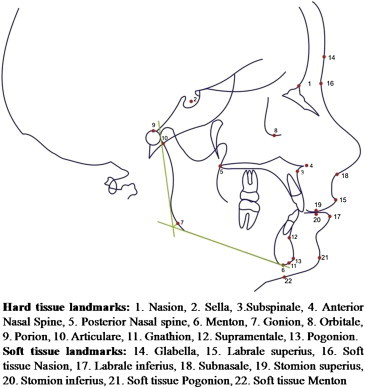
Cephalometric points and landmarks.
Fig. 2.
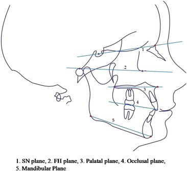
Cephalometric reference planes.
The soft copies of all lateral cephalograms were transferred to Nemoceph cephalometric software program (Nemotec, Version6.0). The images were calibrated by identifying two crosshairs 10 mm apart. The image enhancement features of the software, like brightness, contrast adjustment and magnification were used as needed to identify individual cephalometric landmarks as precisely as possible with the help of mouse/cursor. Once all the landmarks were marked, these landmarks were again adjusted and corrected for accurate measurements. All angular and linear measurements were automatically calculated by the tracing software. The data so obtained was subjected to statistical analysis.
2.1. The various measurements done were as follows
Fig. 3 shows following linear measurements: 1. Anterior cranial base length (Se– N) 2. Posterior cranial base length (S-Ar) 3. Posterior facial height (S-Go) 4. Ramus height (Ar-Go) 5. Mandibular base length (Go-Me) 6. Maxillary base length (PNS to A I on PP) 7. Anterior facial height (N–Me).
Fig. 3.
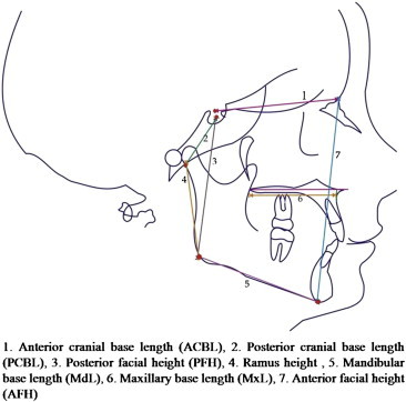
Linear measurements.
Fig. 4 shows following linear measurements: 1. Upper lip length (Sn-Stms) 2. Lower lip length (Stmi-Me') 3. Upper lip prominence (Ls-Sn-Pg') 4. Lower lip prominence (Li–Sn–Me') 5. Upper incisor to NA 6. Lower incisor to NB.
Fig. 4.
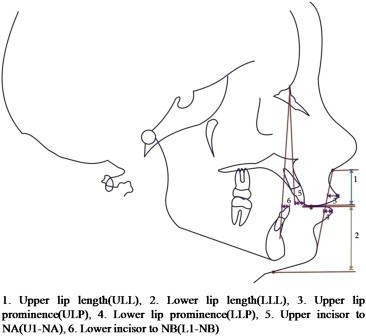
Linear measurements.
Fig. 5 shows following angular measurements: 1. SNA angle 2. SNB angle 3. ANB angle 4. Upper incisor to NA 5. Lower incisor to NB 6. Interincisal angle 7. SN-mandibular plane angle (SN-Go-Gn).
Fig. 5.
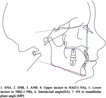
Angular measurements.
Fig. 6 shows following angular measurements: 1. Saddle angle (N–S-Ar), 2. Articular Angle (S-Ar-Go), 3. Gonial angle (Ar-Go-Me), 4. SN-occlusal plane angle 5. Facial angle (N-Pg to FH), 6. Soft tissue facial convexity (G-Sn to Pog').
Fig. 6.
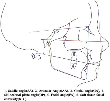
Angular measurements.
2.2. Method of determining accuracy
The intraclass correlation coefficient with r > 0.75, would show good reproducibility of the method. The measurements would be considered clinically acceptable if the mean measurement differences between digital and manual methods were less than 2 units (1unit = 1 mm for linear measurements and 1° for angular measurements).
2.3. Statistical analysis
The statistical analysis was done using SPSS (Statistical Package for Social Sciences) Version 15.0 statistical Analysis Software. Intraexaminer error was evaluated by repeating tracings of randomly selected 10 radiographs (performed at the interval of 2 weeks) and the difference between the two sets of readings was statistically nonsignificant. Systemic error i.e. difference in measurements related to the methods investigated was calculated by using paired t-tests based on equality of variance between the digital and manual tracings.
3. Results
Comparison of mean difference in the two measuring techniques i.e. manual and digital techniques for linear measurements is shown in Table 1 and for angular measurements in Table 2. Amongst these linear measurements, values obtained by the manual technique were higher in comparison with the digital technique for all the measurements except the ramus height, which showed higher value in the digital technique (Table 1). Amongst the angular measurements, ANB, L1 to NB, SA, GA demonstrated higher values in manual technique whereas SNA, SNB, U1 to NA, U1/LI, MP, OP, AA, STC, FA showed higher values in digital technique (Table 2).
Table 1.
Comparison of linear measurements between manual and digital techniques.
| S. no | Parameter | Manual (mean ± SD) | Digital (mean ± SD) | Difference (mean ± SD) | “t” | “p” | “r” |
|---|---|---|---|---|---|---|---|
| 1. | AFH | 106.08 ± 7.04 | 104.95 ± 7.61 | 1.13 ± 1.40 | 5.081 | 0.000 | 0.985 |
| 2. | PFH | 73.06 ± 7.08 | 72.45 ± 7.83 | 0.61 ± 1.71 | 2.251 | 0.030 | 0.979 |
| 3. | Ramus Height | 44.30 ± 5.78 | 44.37 ± 6.30 | −0.07 ± 2.35 | −0.195 | 0.846 | 0.928 |
| 4. | ULL | 18.95 ± 2.41 | 18.47 ± 2.61 | 0.48 ± 1.47 | 2.059 | 0.046 | 0.832 |
| 5. | LLL | 41.15 ± 4.65 | 40.23 ± 4.97 | 0.92 ± 1.67 | 3.497 | 0.001 | 0.942 |
| 6. | ACBL | 65.26 ± 4.17 | 64.20 ± 4.65 | 1.06 ± 1.65 | 4.070 | <0.001 | 0.935 |
| 7. | PCBL | 33.90 ± 3.58 | 32.48 ± 4.20 | 1.42 ± 1.75 | 5.135 | <0.001 | 0.911 |
| 8. | MxL | 44.46 ± 2.69 | 43.64 ± 3.13 | 0.83 ± 2.21 | 2.357 | 0.024 | 0.720 |
| 9. | MdL | 65.70 ± 5.64 | 65.04 ± 6.40 | 0.66 ± 2.05 | 2.029 | 0.049 | 0.950 |
| 10. | U1 to NA | 7.35 ± 3.24 | 7.34 ± 3.25 | 0.01 ± 1.05 | 0.060 | 0.952 | 0.947 |
| 11. | L1 to NB | 7.36 ± 2.69 | 6.87 ± 2.81 | 0.49 ± 0.76 | 4.077 | <0.001 | 0.963 |
| 12. | ULP | 6.21 ± 2.25 | 6.08 ± 2.55 | 0.13 ± 1.18 | 0.699 | 0.489 | 0.888 |
| 13. | LLP | 5.88 ± 2.72 | 5.25 ± 2.75 | 0.63 ± 0.83 | 4.758 | <0.001 | 0.954 |
p < 0.05 – Significant; p < 0.01 – Very significant; p < 0.001 – Most significant.
Table 2.
Comparison for angular measurements between manual and digital techniques.
| S. no. | Parameter | Manual (mean ± SD) | Digital (mean ± SD) | Difference (mean ± SD) | “t” | “p” | “r” |
|---|---|---|---|---|---|---|---|
| 1. | SNA | 82.63 ± 3.79 | 82.76 ± 4.17 | −0.141 ± 0.80 | −0.484 | 0.631 | 0.902 |
| 2. | SNB | 78.35 ± 4.49 | 78.89 ± 5.05 | −0.541 ± 0.72 | −1.967 | 0.056 | 0.942 |
| 3. | ANB | 4.23 ± 3.39 | 3.89 ± 3.58 | 0.331 ± 0.18 | 1.779 | 0.083 | 0.944 |
| 4. | U1 to NA | 30.33 ± 8.36 | 30.56 ± 8.40 | −0.242 ± 0.67 | −0.556 | 0.581 | 0.949 |
| 5. | L1 to NB | 30.05 ± 7.46 | 29.86 ± 7.02 | 0.202 ± 0.53 | 0.488 | 0.629 | 0.941 |
| 6. | IIA | 115.10 ± 12.42 | 115.70 ± 12.58 | −0.602 ± 0.74 | −1.371 | 0.178 | 0.976 |
| 7. | MP | 28.23 ± 6.07 | 29.11 ± 6.32 | −0.881 ± 0.74 | −3.215 | 0.003 | 0.962 |
| 8. | OP | 18.85 ± 3.10 | 23.63 ± 2.79 | −4.78 ± 2.00 | −15.138 | 0.000 | 0.775 |
| 9. | SA | 125.78 ± 5.37 | 124.76 ± 5.48 | 1.02 ± 2.32 | 2.771 | 0.009 | 0.909 |
| 10. | AA | 141.75 ± 5.61 | 143.66 ± 6.76 | −1.91 ± 2.60 | −4.642 | 0.000 | 0.929 |
| 11. | GA | 122.90 ± 6.41 | 120.91 ± 7.43 | 1.99 ± 2.00 | 6.294 | 0.000 | 0.969 |
| 12. | STC | 15.80 ± 6.85 | 16.02 ± 7.06 | −0.22 ± 1.75 | −0.786 | 0.437 | 0.969 |
| 13. | FA | 87.50 ± 3.92 | 88.50 ± 4.71 | −1.00 ± 1.70 | −3.716 | 0.001 | 0.938 |
p < 0.05 – Significant; p < 0.01 – Very significant; p < 0.001 – Most significant.
4. Discussion
Cephalograms have been used widely, both as clinical tool and as a research technique for the study of craniofacial growth and orthodontic treatment. Precision and reproducibility in data obtained from cephalometrics is important for the orthodontist. Errors in conventional methods arise from radiographic acquisition, landmark identification, and measurement.2,3,13−16
To overcome the errors of conventional radiography, digital cephalometry, which allowed the operator to manipulate data on the computer thereby facilitating the complex analysis and organization became popular.
Most of the studies done previously compared the digital cephalometric analysis of either scanned or photographed images to their analog hard copy by manual tracings or comparison of soft copy to its analog hard copy, where cephalograms were taken by using sandwich technique. The present study was done on the cephalograms taken by direct digital radiography, charged couple device (CCD) technique and its soft copies and digital printouts were obtained. Previous studies have been done to compare the cephalometric measurements of monitor-displayed images using different softwares7,15–17 but not the “Nemoceph” software that was used for analysis in the present study. The parameters selected included all the areas of the cephalogram for overall meaningful and reliable comparison between digital and manual tracing techniques.
The results of the study showed that the linear measurements i.e. anterior facial height (AFH), Posterior facial height (PFH), Upper lip length (ULL), Lower lip length (LLL), Anterior cranial base length (ACBL), Posterior cranial base length (PCBL), Maxillary length (MxL), Mandibular length (MdL), Lower incisor to NB line (L1 to NB) and Lower lip protrusion (LLP) showed statistically significant differences in the digital and manual methods. Similar to the findings of this study, Santoro et al17 and Celik et al6 found significant differences in anterior facial height (AFH) and posterior facial height (PFH) ratio between both the tracing techniques. Agarwal et al18 found significant differences for both anterior cranial base length (ACBL) and posterior cranial base length (PCBL). Celik et al6 found significant difference for mandibular length (MdL), while contrary to present study, Singh et al19 did not find any significant difference between the digital and manual tracing for mandibular length (MdL).
Gregston et al,20 Ozsoy et al12 and Krishnaraj et al21 found significant differences in mean values of U1to NA and L1to NB, in contrast of this, Bruntz et al1 and Paixao et al22 did not find significant difference in the two techniques for these parameters. Contrary to the findings of present study, Uysal et al,11 Celik et al6 and Agarwal et al18 showed significant difference only for U1 to NA, but did not find significant difference for L1 to NB.
In the present study, the significant differences found for both Upper and lower lip length (ULL and LLL) supports the findings of Agarwal et al,18 while contrary to this, Celik et al6 did not find any significant difference between the two techniques for upper lip length (ULL). The present study showed significant difference for the lower lip protrusion (LLP) between the two techniques, this is corroborated by the findings of Cooke and Wei23 that lip prominence points are poor landmarks to identify.
All the linear measurements that showed statistically significant difference were clinically acceptable based on the criteria stated by Chen et al8 and Schulze et al.9 According to them, when the measurement difference is less than 2 units (mm or degree) i.e. within the one standard deviation of norm values of conventional cephalometric analysis between the two techniques, it is considered to be clinically insignificant or clinically acceptable.
The angular measurements, Mandibular plane angle (MP), Occlusal plane angle (OP), Saddle angle (SA), Articular angle (AA), Gonial angle (GA) and Facial angle (FA) showed statistically significant differences in the digital and manual methods. Naini et al24 and Santoro et al18 found significant difference for mandibular plane angle (MP) while contrary to this, Uysal et al,11 Celik et al6 and Singh et al19 found no significant difference between the two techniques for the same. Chen et al8 and Gregston et al20 found significant difference for Occlusal plane angle (OP), which supports the finding of this study, while contrary to the present study, Lai et al25 did not find any significant difference for mandibular plane angle (MP) as well as Occlusal plane angle (OP).
Contrary to the findings of the present study, Ozsoy et al12 and Krishnaraj et al21 did not find significant difference for mandibular plane angle (MP), Saddle angle (SA), Articular angle (AA) and Gonial angle (GA). In contrast to this Agarwal et al18 found significant difference for the mandibular plane angle (MP), Occlusal plane angle (OP) and Gonial angle (Go) whereas no difference was found for Saddle angle (SA) and Articular angle (AA) in their study.
The significant difference found for Facial angle (FA) in this study was supported by the findings of Bruntz et al1 whereas it disagreed with the results of Agarwal et al.18 No significant difference was found in the present study for the angles SNA, SNB, ANB, U1to NA, L1 to NB and Interincisal angle, similar to the findings of Bruntz et al,1 Uysal et al11 and Paixao et al,22 and contrary to this, Naini et al24 found significant difference between two techniques for the above parameters.
Chen et al8 and Lai et al25 found that there was no significant difference for SNA, SNB and ANB, whereas significant difference was found for interincisal angle, while Gregston et al20 and Celik et al6 found significant difference only in L1 to NB angular value and there was no difference found for rest of the parameters. Santoro et al17 found significant differences for SNA, ANB and interincisal angle, while there was no difference found for SNB, whereas contrary to this Ozsoy et al12 showed significant differences for SNB only, and there was no significant difference found for other parameters.
Krishnaraj et al21 found significant difference in U1-NA, and no differences were found for SNA, SNB and L1 to NB, while Agarwal et al18 found significant difference for SNA, ANB and U1 to NA, and there was no difference found for SNB, L1to NB and interincisal angle. Singh et al19 found significant difference for SNB and L1 to NB, while SNA, ANB, U1 to NA and Interincisal angle showed no differences for the two techniques.
The present study showed that there was no significant difference found for soft tissue facial convexity. This finding supports the finding of Kublashvilli,26 while contrary to this, Agarwal et al18 found statistically significant difference between the two techniques for soft tissue facial convexity parameter.
Amongst all the angular measurements that showed statistically significant difference between the manual and digital technique, all were clinically acceptable except SN-OP angle as per the criteria8,9 quoted previously. The SN-occlusal plane measurements were affected by the double images of the occlusal surfaces of the teeth, interfering with easy identification of the occlusal plane. Also the occlusal plane was marked automatically on the digital image and may not correspond to that drawn in the manual method, which could be responsible for variation in readings of this parameter between the two techniques.
The differences in measurements between the soft- and hard copies for the present study were more significant for linear than angular measurements similar to the results of Lai et al25 and Celik et al.6 Differences in measurements of 10 out of 13 linear measurements were significant while differences in measurements of only 6 out of 13 angular measurements were statistically significant.
The difference in measurements between the two methods could be due to the fact that certain hard tissue landmarks such as articulare, gonion, porion, menton, gnathion, orbitale and point ‘A’ lie on poorly defined outlines or low contrast areas, and also some of the soft tissue landmarks such as Li, Ls, Me', Pog' and Sn are present on the contoured area, making them difficult to locate on radiographs in manual technique. These are substantiated by the findings of Houston et al,15 Gregston et al,20 Santaro et al17 and Ozsoy et al,12 who also found difficulties in locating landmarks Ar, Gn, Go, Po, Or, lower incisor apex, Me, Pog, and point A. During manual tracing different reference planes were constructed to assist in identifying points Gn, Me and Go, which was not possible with on-screen digitization, where these points were marked by the operator with a single click of the mouse without any reference plane construction. Baumrind and Frantz3 reported tracing difficulties of the incisor position and variation in incisor angular measurements between tracing methods.
Thus, it can be stated that Nemoceph digital imaging software program can be reliably used with good accuracy for the measurements of most of the parameters used in routine clinical practice. Further research needs to be done on the evaluation of digital cephalometry with a larger sample size to ensure reproducibility and reliability of the cephalometric software program.
5. Conclusions
The following conclusions were drawn from the study:
-
1.
Digital measurements obtained from monitor-displayed images (soft copy) were found to be reproducible and comparable to the manual method done on its hard copy, for all the measurements except occlusal plane angle (SN-Occlusal plane), which showed clinically significant difference between the two techniques.
-
2.
Amongst the linear measurements, Anterior facial height (AFH), Posterior facial height (PFH), Upper lip length (ULL), Lower lip length (LLL), Anterior cranial base length (ACBL), Posterior cranial base length (PCBL), Maxillary length (MxL), Mandibular length (MdL), Lower incisor to NB line (L1 to NB) and Lower lip protrusion (LLP) showed statistically significant difference between the two techniques, but were clinically acceptable.
-
3.
Amongst the angular measurements, Mandibular plane angle (MP), Occlusal plane angle (OP), Saddle angle (SA), Articular angle (AA), Gonial angle (GA) and Facial angle (FA) showed statistically significant difference between the two techniques, but were clinically acceptable.
-
4.
Measurements of all linear variables were found to be higher by manual technique except ramus height. Angular measurements ANB, L1 to NB, Saddle angle (SA) and Gonial angle (GA) were measured higher by manual technique and rest of the measurements were measured higher by digital technique.
Conflicts of interest
All authors have none to declare.
References
- 1.Bruntz L.Q., Palomo J.M., Baden S., Hans M.G. A comparison of scanned lateral cephalograms with corresponding original radiographs. Am J Orthod Dentofac Orthop. 2006;130:340–348. doi: 10.1016/j.ajodo.2004.12.029. [DOI] [PubMed] [Google Scholar]
- 2.Baumrind S., Frantz R.C. The reliability of head film measurements 1. Landmark identification. Am J Orthod Dentofac Orthop. 1971;60:111–127. doi: 10.1016/0002-9416(71)90028-5. [DOI] [PubMed] [Google Scholar]
- 3.Baumrind S., Frantz R.C. The reliability of head film measurements 2. Conventional angular and linear measurements. Am J Orthod Dentofac Orthop. 1971;60:505–517. doi: 10.1016/0002-9416(71)90116-3. [DOI] [PubMed] [Google Scholar]
- 4.Baumrind S., Miller D.M. Computer aided headfilm analysis. The University of California San Franciso method. Am J Orthod Dentofac Orthop. 1980;78:41–65. doi: 10.1016/0002-9416(80)90039-1. [DOI] [PubMed] [Google Scholar]
- 5.Geelen W., Wenzel A., Gotfredsen E., Kruger M., Hansson L.G. Reproducibility of cephalometric landmarks on conventional film, hardcopy, and monitor displayed images obtained by the storage phosphor technique. Eur J Orthod. 1998;20:331–340. doi: 10.1093/ejo/20.3.331. [DOI] [PubMed] [Google Scholar]
- 6.Celik E., Ozsoy O.P., Memikoglu T.U.T. Comparison of cephalometric measurements with digital versus conventional cephalometric analysis. Eur J Orthod. 2009;31(3):241–246. doi: 10.1093/ejo/cjn105. [DOI] [PubMed] [Google Scholar]
- 7.Johnson D.R., English J., Gallerano R. Comparison of hand-traced and computerized cephalograms: landmark identification, measurement, and superimposition accuracy. Am J Orthod Dentofac Orthop. 2008;133:56–64. doi: 10.1016/j.ajodo.2006.03.041. [DOI] [PubMed] [Google Scholar]
- 8.Chen S.K., Chen Y.J., Yao C.C.J., Chang H.F. Enhanced speed precision of measurement in a computer assisted digital cephalometric analysis system. Angle Orthod. 2004;74:501–507. doi: 10.1043/0003-3219(2004)074<0501:ESAPOM>2.0.CO;2. [DOI] [PubMed] [Google Scholar]
- 9.Schultze R.K.W., Dent M., Gloede M.B., Doll G.M. Landmark identification on direct digital versus film based cephalometric radiographs – A human skull study. Am J Orthod Dentofac Orthop. 2002;122:635–642. doi: 10.1067/mod.2002.129191. [DOI] [PubMed] [Google Scholar]
- 10.Sayinsu K., Isok F., Trakyali G., Arun T. An evaluation of errors in cephalometric measurements on scanned cephalometric images and conventional tracings. Eur J Orthod. 2007;29:105–108. doi: 10.1093/ejo/cjl065. [DOI] [PubMed] [Google Scholar]
- 11.Uysal T., Baysal A., Yagci A. Evaluation of speed, repeatability, and reproducibility of digital radiography with manual versus computer-assisted cephalometric analyses. Eur J Orthod. 2009;31:523–528. doi: 10.1093/ejo/cjp022. [DOI] [PubMed] [Google Scholar]
- 12.Ozsoy O.P., Gokcelik A., Menkoglu T.U.T. Differences in cephalometric measurements: a comparison of digital versus hand-tracing methods. Eur J Orthod. 2009;31(3):254–259. doi: 10.1093/ejo/cjn121. [DOI] [PubMed] [Google Scholar]
- 13.Tsorovas G., Karsten A.L.A. A comparison of hand-tracing and cephalometric analysis computer programs with and without advanced features- accuracy and time demands. Eur J Orthod. 2010;32:721–728. doi: 10.1093/ejo/cjq009. [DOI] [PubMed] [Google Scholar]
- 14.Richardson A. An investigation into reproducibility of some points, planes and lines used in cephalometric analysis. Am J Orthod Dentofac Orthop. 1966;52:637–651. doi: 10.1016/0002-9416(66)90212-0. [DOI] [PubMed] [Google Scholar]
- 15.Houston W.J.B., Maher R.E., McElroy D., Sherriff M. Sources of error in measurements from cephalometric radiographs. Eur J Orthod. 1986;8:149–151. doi: 10.1093/ejo/8.3.149. [DOI] [PubMed] [Google Scholar]
- 16.Forsyth D.B., Shaw W.C., Richmond S. Digital imaging of cephalometric radiology. Part I: advantages and limitations of digital imaging. Angle Orthod. 1996;66:37–42. doi: 10.1043/0003-3219(1996)066<0037:DIOCRP>2.3.CO;2. [DOI] [PubMed] [Google Scholar]
- 17.Santoro M., Jarjoura K., Cangialosi T.J. Accuracy of digital and analogue cephalometric measurements assessed with the sandwich technique. Am J Orthod Dentofac Orthop. 2006;129:345–351. doi: 10.1016/j.ajodo.2005.12.010. [DOI] [PubMed] [Google Scholar]
- 18.Agarwal N., Bagga D.K., Sharma P. A comparative study of cephalometric measurements with digital versus manual methods. J Ind Orthod Soc. 2011;45(2):84–90. [Google Scholar]
- 19.Singh P., Davies T.I. A comparison of cephalometric measurements: a picture archiving and communication system versus the hand-tracing method – a preliminary study. Eur J Orthod. 2010;33:350–353. doi: 10.1093/ejo/cjq087. [DOI] [PubMed] [Google Scholar]
- 20.Gregston M.D., Kula T., Hardman P., Glaros A., Kula K. A comparison of conventional and digital radiographic methods and cephalometric analysis software: I. Hard tissue. Sem Orthod. 2004;10:204–211. [Google Scholar]
- 21.Krishnaraj R., Balasubramaniam M.R., Shetty R.S., Arumugam E. A comparison of conventional, digitized and digital methods of hard tissue cephalometric parameters. SRM University J Dent Sci. 2010;1(1):68–74. [Google Scholar]
- 22.Paixao M.B., Sobral M.C., Vogel C.J., Araujo T.M. Comparative study between manual and digital cephalometric tracing using dolphin imaging software with lateral radiographs. Dent Press J Orthod. 2010;15(6):123–130. [Google Scholar]
- 23.Cooke M.S., Wei S.H. Cephalometric errors: a comparison between repeat measurements and retaken radiographs. Aust Dent J. 1991;36:38–43. doi: 10.1111/j.1834-7819.1991.tb00806.x. [DOI] [PubMed] [Google Scholar]
- 24.Naini F.B., Otasevic M., Vasir N.S. A comparison of manual tracing, digitising and computer cephalometric analysis. Virtual J Orthod. 2001;3(4):94–99. [Google Scholar]
- 25.Lai E.H.H., Chen C.S.K., Chang Z.C., Yao C.C., Chen Y.J. Cephalometric analysis using digital radiography acquired by a storage phosphor imaging system – a comparison of reading soft- and hard-copies. J Dent Sci. 2007;2(2):65–67. [Google Scholar]
- 26.Kublashvili T., Kula K., Craven R., Vadachkoria Z. Reliability of soft tissue cephalometric parameters using conventional and digital cephalometric radiogram. Ann Biomed Res Educ. 2002;2(4):316–322. [Google Scholar]