Abstract
Predominantly closed-cell low density shape memory polymer (SMP) foam was recently reported to be an effective aneurysm filling device in a porcine model (Rodriguez et al., Journal of Biomedical Materials Research Part A 2013: (http://dx.doi.org/10.1002/jbm.a.34782)). Because healing involves blood clotting and cell migration throughout the foam volume, a more open-cell structure may further enhance the healing response. This research sought to develop a non-destructive reticulation process for this SMP foam to disrupt the membranes between pore cells. Non-destructive mechanical reticulation was achieved using a gravity-driven floating nitinol pin array coupled with vibratory agitation of the foam and supplemental chemical etching. Reticulation resulted in a reduced elastic modulus and increased permeability, but did not impede shape memory behavior. Reticulated foams were capable of achieving rapid vascular occlusion in an in vivo porcine model.
1. Introduction
An intracranial aneurysm, or abnormal bulging of an artery wall within the brain, is susceptible to rupture, having a great potential to result in mental debilitation or death1. Rupture of an aneurysm, or subarachnoid hemorrhage, results in bleeding out into the spaces of the brain. The cause of aneurysm growth and rupture is not fully known, but is thought to be due to abnormal blood flow patterns, local shear stresses and the weakened state of the arterial wall2. Due to the inability to predict the occurrence of a rupture of such a malformation, and its potential to have a fatal or harmful outcome, it is advantageous for the patient to be treated as early in the disease progression as possible.
In the past couple of decades, endovascular treatment has become the preferred treatment versus surgical methods. This is mainly due to the significantly less invasive nature of endovascular treatments, with attendant reductions in recovery time and cost when compared to surgical craniotomy. Previously, it has been shown that polyurethane based shape memory polymer (SMP) foam is a biocompatible material effective for aneurysm filling3,4 in a porcine animal model. Additionally, other non-shape memory polymeric polyurethane and polycarbonate foams have been explored for the purpose of vascular5 and abdominal aortic aneurysm6 occlusion with promising results. In this research we sought to develop a self-actuating vascular occlusion device (VOD) made of SMP foam to be delivered via endovascular methods.
It has been shown by Singhal, et al., in 2012, that polyurethane based SMP formulations can be tailored to be blown into foams with various actuation temperatures, densities and pore cell sizes7. These ultra-low density SMP materials have the ability to be temporarily programmed to a secondary compressed shape and maintain that shape until the material's temperature is elevated above its transition temperature. Around the transition temperature, the material regains its original shape. This ability to maintain a compressed shape until exposed to an increase in temperature above its transition temperature makes these materials excellent candidates for endovascular applications. Given their shape memory capability, tunable pore cell size, tunable actuation temperature and proven biocompatibility3, we desire to develop these materials as an endovascularly delivered VOD.
These foams possess a predominantly closed cell microstructure, which may not be optimal for aneurysm occlusion and subsequent healing. Post processing to reticulate the foam, or remove/puncture the thin membranes between pore cells while leaving the net-like foam backbone intact8, will likely enable blood flow to more easily permeate throughout the foam, and allow for a forming clot to stabilize the device within the aneurysm. This permeation of blood throughout the material also enables the desired cellular components necessary to induce healing to more easily migrate into the volume of foam after clotting has occurred.
Reticulation has been achieved by multiple post-processing methods within industry, including caustic leaching8 via exposure of the foam to a caustic bath for a specific amount of time, temperature and speed, thermal reticulation via a controlled burning of the membranes with the ignition of hydrogen and oxygen gases within a vessel housing the foam, or cyclic loading and unloading of the material. The act of reticulation changes the overall physical properties of foam. In general, it has been shown that with removal of membranes there is a decrease in the resistance to mechanical compression9. There is also an increase in tensile properties, such as elongation and tearing strength9. When developing a reticulation procedure for SMP foam, care must be taken to avoid damaging the foam struts to preserve shape memory behavior and minimize the impact on its mechanical properties.
This research sought to develop a methodology for reticulation of membranes between the pores of SMP foam without damaging the native structure9 or shape memory ability, with the intent of using these processed materials as a VOD. A viable non-destructive method of reticulation was developed involving mechanical membrane puncture and supplemental chemical etching, and the effect of reticulation on the mechanical properties of the foam was determined. To demonstrate proof of concept for these materials as a VOD, the occlusion time was determined via catheter implantation of reticulated foam devices within the vasculature of a porcine animal model. This research may accelerate the process of development of these materials as VODs for aneurysm treatment or other vascular applications aimed at achieving hemostasis.
2. Materials and Methods
2.1. Foam synthesis
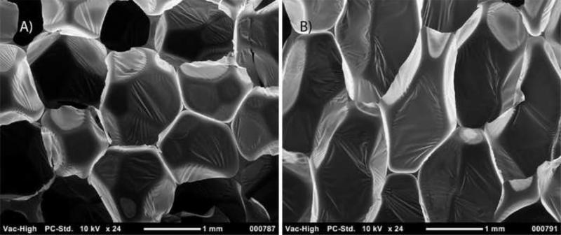
Two versions of SMP foam were fabricated by the method described by Singhal et al., in 2012 and 20137,10. One version contained 100% hexamethylene diisocyanate (HDI) and the other contained 20% HDI and 80% trimethyl-1,6-hexamethylene diisocyanate (TMHDI) for the isocyanate monomer in the polyurethane reaction. The less hydrophobic 100% HDI foam was made specifically for vessel implantation studies to allow for immediate self-actuation of the VOD in vivo without the need for external heating. The foam actuates at body temperature after exposure to moisture in the blood which causes a drop in the material's transition temperature. The other formulation was used for development of the reticulation system and mechanical testing. Both foams were reticulated and chemically post-processed in the same manner. Aside from their different hydrophobicities, these two foams share very similar mechanical properties and shape memory characteristics10. During the foaming process, the material is constrained by the side walls of the container and unconstrained from above as it rises. Due to these conditions and their ultra-low densities9, the foams have an anisotropic morphology as demonstrated in Figure 1.
Figure 1.
SEM cross-section images of native SMP foam in (A) horizontal (x-y) and (B) vertical (x-z) planes. The cells are elongated in the direction of the foam rise (z, vertical). The membranes between cells are evident.
2.2. Nitinol wire characterization
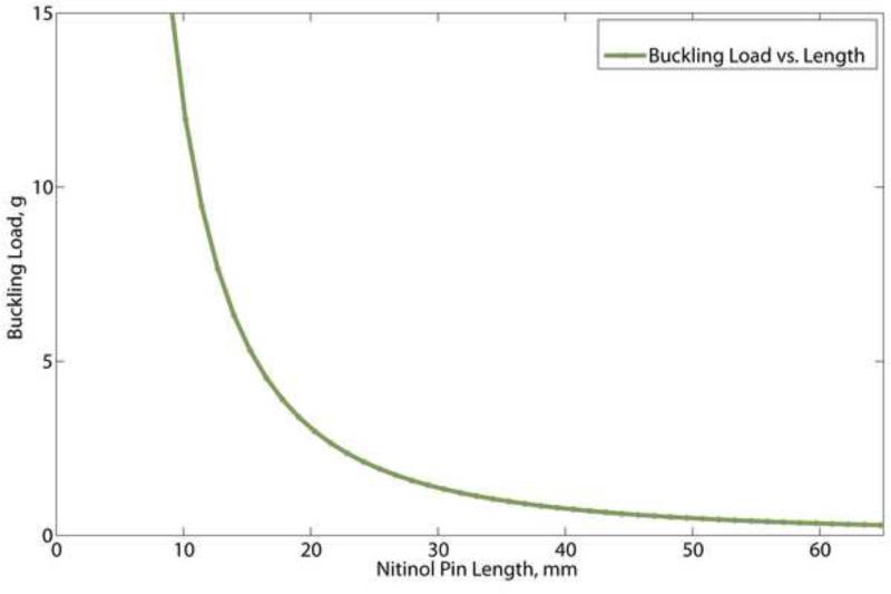
Nitinol wire pins were chosen as the means of mechanically reticulating the foam. Straight drawn nitinol wire (0.008” diameter) was purchased from Nitinol Devices & Components, Inc. (Fremont, CA), and was tested via strain to failure according to ASTM F2516 – 07 Standard Test Method for Tension Testing of Nickel-Titanium Superelastic Materials. Tests were performed on six samples using an Instron 5965 load frame (Instron©, Norwood, MA) equipped with a 500 N load cell. The Young's modulus and buckling load (critical load at which a column bows outward) of the nitinol wire were calculated. Young's modulus was calculated as the ratio of true stress to true strain at low strain. The buckling load was determined from the Euler column formula
where Fcr is the minimal buckling load, K accounts for the end conditions, E is the Young's modulus, L is the length of the column and I is the area moment of inertia for the cross section of a cylindrical column, a circle, given by
where R is the radius of the column. The end conditions, K, are determined as follows: both ends fixed: K = 0.5, one end fixed, one end pivots: K =0.707, both ends pivot: K = 1, one end fixed, one end free: K = 2. Since the end of the nitinol pin is free to move laterally when interacting with the foam surfaces, K was taken to be 2.
2.3. Mechanical reticulation system
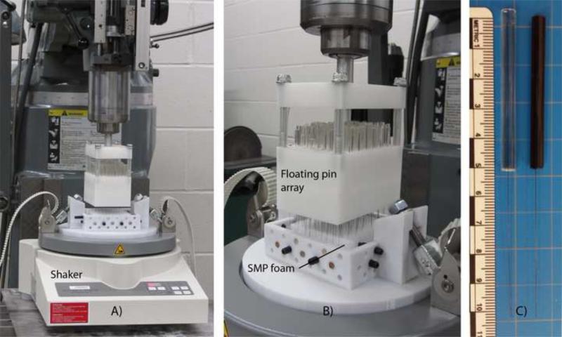
The mechanical reticulation system consisted of two main components: (1) a gravity-driven floating nitinol pin array and (2) a vertically oscillating vibratory shaker upon which the foam was mounted for reticulation (Figure 2A). Each pin was made by casting a nitinol wire in a 1 ml syringe filled with EpoxAcast® 690 (Smooth-On, Inc., Easton, PA) doped with < 1 μm tungsten particulate (Alfa Aesar, Ward Hill, MA). A 50-mm length of nitinol protruded from the cast polymer cylinder (Figure 2B). The pins were loaded perpendicular to the top surface of the foam in individual channels drilled in a delrin block. The low-friction channels allowed unrestricted vertical motion of the pins. The pins were spaced 7 mm apart in a radial pattern. With the free ends of the floating nitinol pins in contact with the foam, the foam was agitated (0.25 mm amplitude) by the vertically oscillating shaker (Fritsch, Analysette 3 Spartan pulverisette 0), allowing for gravity-driven downward movement of the pins. Agitation continued until the pins penetrated the full thickness of the foam. The delrin block, which was chucked into a Bridgeport milling machine (Hardinge Inc., Elmira, NY) for controlled step wise movement, was then translated horizontally (pins removed) for further reticulation of the foam sample. Samples were punched in a raster manner every 500 μm. The samples were punched in one axis (uni-axial) or three axes (tri-axial). Uni-axial reticulated samples were punched along the direction of foam rise only (z-axis). Tri-axial reticulated samples were punched along the x-, y-, and z-axes by punching along one axis, re-orienting the foam, and punching along a different axis.
Figure 2.
(A) Mechanical reticulation system including the floating nitinol pin array and vibratory foam shaker. (B) Close up of the array punching the foam. (C) Nitinol pins cast in non- doped (left pin) and tungsten-doped polymer (right pin).
2.4. Preliminary mechanical reticulation testing
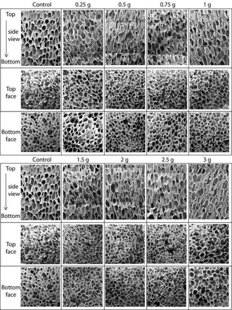
To determine the pin mass necessary to puncture a 30-mm-thick foam sample using the mechanical reticulation system, pins of variable mass were made by varying the amount of tungsten in the cast pins. Pins were made with masses of 0.25, 0.5, 0.75, 1.0, 1.5, 2.0, 2.5 and 3.0 grams. Uni-axial reticulation was performed to assess the effect of pin mass.
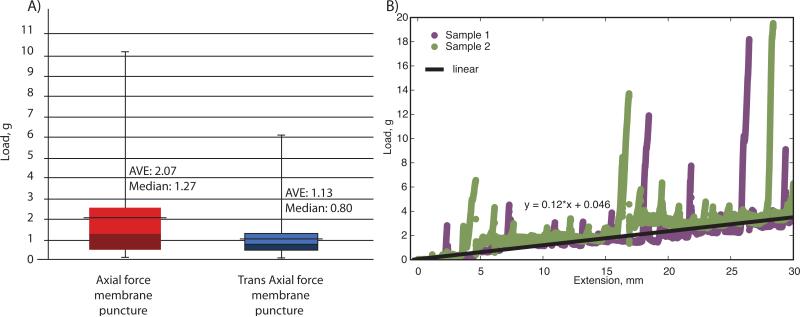
In addition to the method of varying the pin mass using the reticulation system, the membrane strength (minimal force necessary to puncture a membrane) and the friction of a wire passing through the foam were determined via mechanical testing using the Instron load frame equipped with a 50 N load cell. Agitation of the foam was not employed in these tests. A custom grip incorporating a pin vise was used to hold the 0.008” nitinol wire perpendicular to the foam sample. The wire extended 50 mm beyond the grip. All measurements were taken at ambient temperature. The force necessary to puncture a single membrane was determined in both the axial (foam rise) and trans-axial (orthogonal to foam rise) directions to assess potential differences due to the anisotropic foam cell structure. The force necessary to puncture a membrane was determined as the first spike in force prior to a sharp decrease in force encountered within the first 2 mm of foam. This distance was chosen due to the average pore cell size being roughly 1 mm in diameter. Force spikes greater than 10.5 g were likely caused by direct interaction with a strut, not a membrane, and were ignored. One hundred and fifty four (154) measurements in the axial direction and 153 measurements in the trans-axial direction were made. For measurement of friction between the nitinol wire and the foam as it penetrated through the 30-mm-thick foam, the crosshead was translated at a rate of 1 mm/min while the load was recorded. Two separate measurements were made. The friction is reported as the slope of the load vs. extension data, excluding the spikes where the nitinol wire tip directly contacted a membrane or strut.
2.5. Chemical etching and final cleaning
In specified cases mechanical reticulation was supplemented by chemical etching to assess the effect of more thorough membrane removal as opposed to membrane puncture. To attempt to remove residual membranes after mechanical reticulation the foams were immersed into a 5N NaOH solution for 30 minutes while sonicated using a 5510R-DTH and 3510R-DTH ultrasonic cleaner (Branson® Ultrasonics Corp., Danbury, CT). The samples were then repeatedly rinsed with RO water to neutralize the samples. All samples (etched or not) were finally cleaned using the protocol outlined by Rodriguez et al. in 20133. The samples were then dried for approximately three hours under vacuum at 90 °C.
2.6. Imaging foam microstructure
Dried foam samples were sputter coated with gold using a Cressington 108 sputter coater, model 6002-8 (Ted Pella, Inc., Redding, CA) for 60 seconds at a distance of 3 cm. Imaging of the SMP foam was done before and after reticulation via low vacuum scanning electron microscopy (LV-SEM) using a NeoScope JCM-5000 (Jeol USA, Inc., Peabody, MA).
2.7. Mechanical characterization of foam
Mechanical testing of SMP foam was performed in compression mode according to ASTM D1621 – 10 Standard Test Method for Compressive Properties of Rigid Cellular Plastics using the Instron load frame with a 500N load cell at ambient laboratory temperatures 23 ± 2 °C, as specified within the text. Cylindrical samples 25.4 mm in diameter by 25.4 mm tall of both the non-reticulated and reticulated (chemically etched or not etched) foams were prepared. These samples were frozen in a −80 °C freezer overnight and subsequently lyophilized for 24 hours prior to mechanical testing. To assess the effects of pin mass, uni-axial vs. tri-axial reticulation, and chemical etching, nine different reticulation schemes (including a non-reticulated control) were investigated as outlined in Table 1. Five (5) samples were tested for each scheme.
Table 1.
Reticulation schemes employed for mechanical testing of foams.
| Nitinol Pin Mass | Chemical Etch | Number of Samples Tested | |
|---|---|---|---|
| Uni-axial | 1 g | no | 5 |
| 1 g | yes | 5 | |
| 2 g | no | 5 | |
| 2 g | yes | 5 | |
| Tri-axial | 1 g axial, 1 g trans-axial | no | 5 |
| 1 g axial, 1 g trans-axial | yes | 5 | |
| 2 g axial, 1 g trans-axial | no | 5 | |
| 2 g axial, 1 g trans-axial | yes | 5 | |
| Non-reticulated control | not applicable | no | 5 |
2.8. Permeability measurements
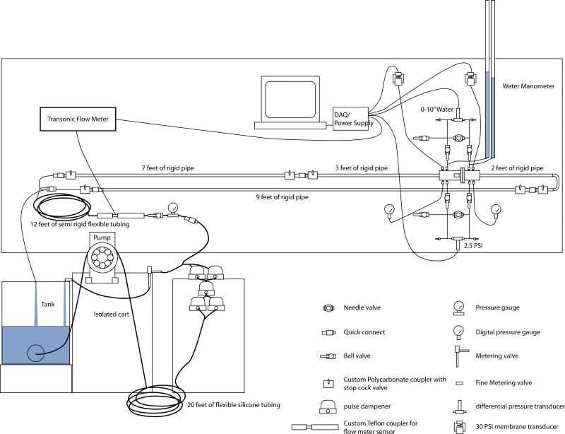
The nine cases of reticulation and etching, having varying densities were measured in triplicate. Each sample was evacuated overnight to remove air bubbles from the samples and was then placed within the chamber of the flow loop (Figure 3). The pressure drop across the foam was measured at various flow rates to determine the permeability. The flow rates measured ranged from 0 to 850 ml/min, or Darcy velocities between 0 to 0.071 m/s for each of the samples. Due to the range of pressures measured, three types of pressure transducers were used for these measurements: 1) 2,482 Pa differential pressure transducer (model # PX409-10WDWUV) 0.08% of range accuracy (Omega Engineering, Inc., Stamford, Connecticut), 2) 17,240 Pa differential pressure transducer (model # PX409-2.5WDWUV) 0.08% of range accuracy, (Omega Engineering, Inc., Stamford, Connecticut) and 3) two 206,800 Pa absolute membrane pressure transducers (model PXM42MG7-400MBARGV) 0.25% of range accuracy (Omega Engineering, Inc., Stamford, Connecticut).
Figure 3.
Diagram of the permeability measurement system.
The reticulated samples were measured with the 2,482 Pa transducer until the differential pressure exceeded the maximum pressure of the transducer in the higher flow rates. Once the maximum differential pressure exceeded the capabilities of the first transducer, the measurements were recorded and read by the 17,240 Pa transducer. As the flow rates decreased on the second half of data acquisition, the data was the acquired from the more sensitive of the measurements available once the transducer was in the proper range of pressures. The set of 206,800 Pa transducers were used to measure the differential pressure of non-reticulated and non-etched control samples. In addition to the pressure transducers, a set of two rigid tubes were fashioned as a water manometer and a set of digital 206,800 Pa pressure gauges (Dwyer Instruments, Michigan City, IN) (Model: DPGWB-06) with 0.01 of range resolution, were used to determine the maximum pressure differential of the highest flow prior to measurement with the transducers (Figure 3).
The pump consisted of a Verderflex® Smart, (Verderflex, England, U.K.) L20 series, peristaltic pump equipped with a non-standard six head roller on an isolated cart, for reduction of pulse within the system. In addition to the six head roller, 20 feet of large diameter (12.7 mm ID and 15.875 mm OD) flexible silicone tubing was placed after the pump just before five pulse dampeners. After the pulse dampeners, there was an additional 12 feet of semi-rigid flexible tubing (12.7 mm ID and 19.1 mm OD) and subsequently ten feet of rigid tubing (15.875 mm ID and 19.05 mm OD) before the pressure chamber. A flow meter probe, attached to a small animal blood flow meter (model number T206) (Transonic Inc., Ithaca, NY) was placed after the five pulse dampeners to quantify the pulse within the system and for flow rate measurements. In an effort to further reduce the pulse of the system seen by the sample, the tank was also isolated on its own cart.
From these measurements the porous media properties were calculated using the Forchheimer-Hazen-Dupuit-Darcy (FHDD) equation:
where the pressure gradient, , is along the sample in the direction of flow (Pa/m), μ is the dynamic viscosity of the fluid (Pa · s), K is the intrinsic permeability of the sample (m2), ν0is the Darcy velocity (average velocity or flow rate, Q, divided by cross-sectional area, A of the sample) (m/s), is the density of the fluid (kg/m3), and C is the form factor of the sample (m-1)11. Permeability is a geometric parameter of the foam and represents the loss in pressure across a sample due to viscous losses, or the coefficient of viscous flow resistance. Permeability is inversely proportional to the surface area of the foam in contact with the fluid. Form factor is also a geometric parameter of the foam and represents the losses in pressure across the sample due to inertial losses, or the coefficient of inertial flow resistance. Form factor is proportional to the projected cross sectional surface area of the foam perpendicular to the flow. These two coefficients represent the forces acting against the motion of fluid flow through the porous media. At low velocities, the viscous forces dominate. While, in higher velocities the inertial losses dominate. Calculated C and K values were reported for three samples of each case measured using water as the fluid.
2.9. In vivo vascular occlusion assessment
Uni-axial and tri-axial reticulated SMP foam samples were cut into 20-30 mm long cylindrical samples using a 10mm diameter biopsy punch. The samples were pre-conditioned by radially compressing to 1 mm diameter using a SC250 stent crimper (Machine Solutions Inc®, Flagstaff, AZ) at 97 °C and heated to expand to their original shape. The SMP foam cylinders were then chemically etched, rinsed, and cleaned. The samples were dried in vacuum and stored in an air-tight container with desiccant. The cylindrical samples were cut to 8 mm diameter using fine-tip scissors and 10 mm long using a razor blade. Samples were then radially compressed to the minimum diameter of approximately 1 mm using the stent crimper at 97 °C, cooled under compression to maintain the compressed shape, and stored in an air-tight container with desiccant until implantation in vivo.
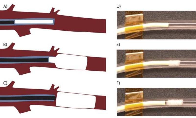
Six (6) devices (3 uni-axial and 3 tri-axial reticulated using 1 g pins and etching) were successfully deployed into multiple hind limb vessels of a three month old, 25 kg pig. Angiography performed prior to implantation of the VODs indicated the diameters of the vessels were on average 2.6 mm in diameter, which was smaller than the 8-mm diameter of the uncompressed VODs; therefore, the devices were able to expand to approximately 33% of their original diameter. A 5F catheter, 0.055” inner diameter, was navigated to the implant site using a 0.035” guidewire. The compressed foam VOD was submerged in room temperature saline for 2-5 minutes and then submerged in 32 °C saline for 3-5 seconds. The device was placed inside the catheter for 5 minutes to allow the foam to begin expanding and then pushed out of the catheter using the 0.035” guidewire (Figure 3A-C). This procedure resulted in expansion of the foam immediately as it emerged out of the catheter as shown in a preliminary benchtop in vitro demonstration (Figure 3D-F). Contrast enhanced fluoroscopy was used to determine when the device had been deployed, by observing the location of the guide wire and if possible a lack of contrast agent in the vessel. After delivery into the vessel, the device expanded to its primary shape and subsequently blocked the vessel. We defined vessel occlusion time as the time after device delivery until injected contrast agent ceased to flow through or past the device; at that point clotting is likely to have occurred. Vessel occlusion time was determined via iodinated contrast injections visualized with angiography 45 seconds after deployment and then at 30 second intervals thereafter5. Average occlusion times were reported.
3. Results and Discussion
3.1. Nitinol pin properties
From the six samples tested it was determined that the average Young's modulus of the nitinol wire was 58.62 ± 0.93 GPa. From this data, the buckling load for different pin lengths was calculated (Figure 4). The buckling load for the 50-mm-long nitinol pins is estimated to be 0.5 g.
Figure 4.
Schematic diagram of endovascular deployment of the SMP foam VOD: (A) the device is pushed near the 5F catheter tip by the guidewire, (B) the guidewire pushes the self- actuating device out of the catheter, and (C) the deployed device fills the vessel lumen. (D-F) In vitro demonstration of VOD deployment showing immediate expansion of the VOD in 37°C (body temperature) water in a silicone tube (3.5 mm inner diameter).
3.2. Mechanical reticulation
Results of varying the mass of the pins for puncturing the membranes throughout the foam thickness are summarized in Figure 5.
Figure 5.
Calculated buckling load of 0.008” diameter nitinol wire.
The average and median mechanical load necessary to puncture a single membrane was determined to be 2.07 ± 2.23 grams and 1.27 grams in the axial direction and 1.13 ± 1.09 grams and 0.80 grams in the trans-axial direction respectively (Figure 6A). Due to the range of measurements, large standard deviation and overlapping data a Wilcoxon Mann test was used to evaluate the difference between the two data sets. The Wilcoxon Mann test resulted in a P_TwoTail value of 0.00252858, which indicated that the two data sets were not the same. Buckling of the nitinol pins may occur based on these measurements, which could influence the reticulation path (and, hence, the number of punctured membranes) as they penetrate through the foam. Friction during penetration though the foam was estimated to be 0.12 g/mm (Figure 6B). The spikes in the data are interactions between the nitinol tip and either a membrane or a strut of the SMP foam, and were intentionally ignored for the friction estimate. However, the spikes generally exceeded the estimated buckling load of the nitinol pins, further suggesting that buckling can occur during reticulation.
Figure 6.
Results of axial reticulation through 30 mm of SMP foam using pins with different masses.
3.3. Effect of reticulation of foam mechanical properties
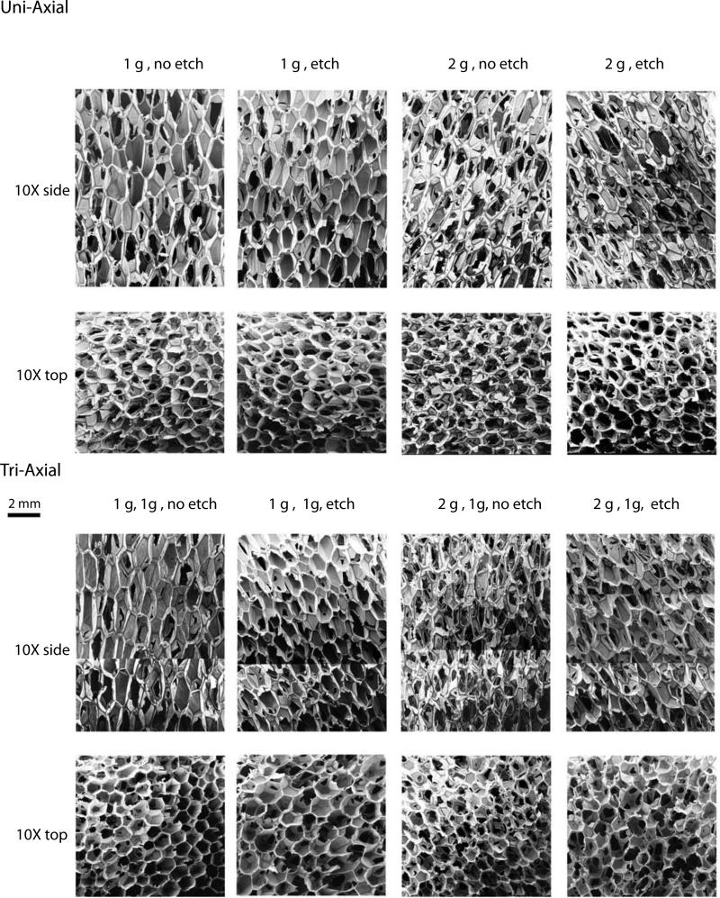
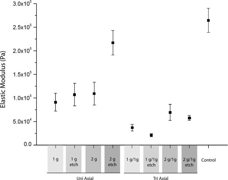
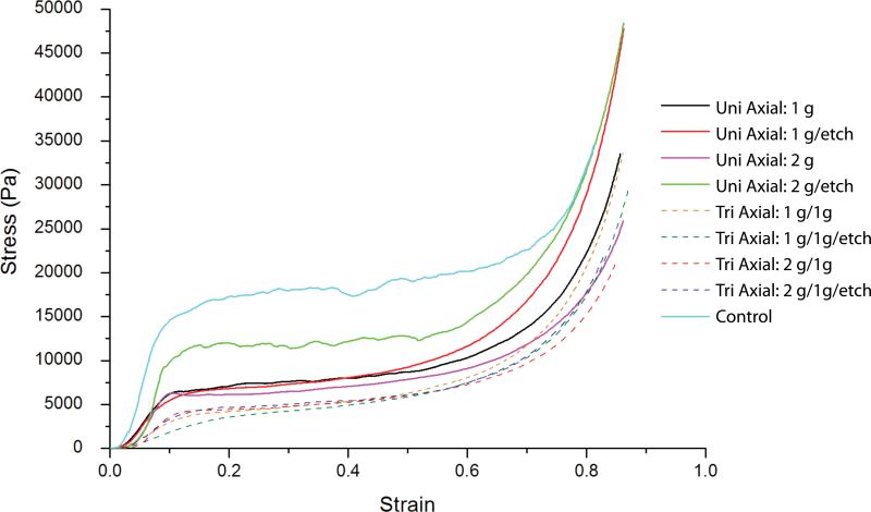
The foams reticulated according to Table 1 are shown in Figure 7. As shown in Figure 8, the non-reticulated control foam had an average elastic modulus of approximately 2.65 X 10⁵ Pa. Reticulation reduced the modulus, with the tri-axial reticulated foams having the lowest moduli. The more extensive disruption of the cell membranes caused by reticulation in multiple axes resulted in higher reduction of the modulus. Closer inspection of the data shows that chemical etching of the uni-axial reticulated foam increased the modulus, while the tri-axial reticulated foams showed a slight decrease in modulus after chemical etching. In both the axial and tri-axial cases, the modulus was higher when 2 gram pins were used for axial reticulation compared to the use of 1 g pins. Figure 9 is a summary of the average stress versus strain curves for the 5 samples tested per case. Following the trend in modulus, the non-reticulated foam had the highest stress plateau before densification, followed by the uni-axial and finally the tri-axial reticulated foams.
Figure 7.
(A) Membrane puncture strength for the axial and trans axial orientations and (B) frictional force experienced between the nitinol wire and SMP foam as it penetrated through a 30 mm thickness of foam in the axial direction with the linear fit of the data represented in black.
Figure 8.
Scanning Electron Microscopy (10X magnification, scale bar = 2 mm) of reticulated foam samples. The cases are summarized in Table 1.
Figure 9.
Elastic moduli for the foams reticulated according to Table 1.
3.4. Permeability of samples
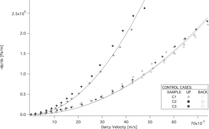
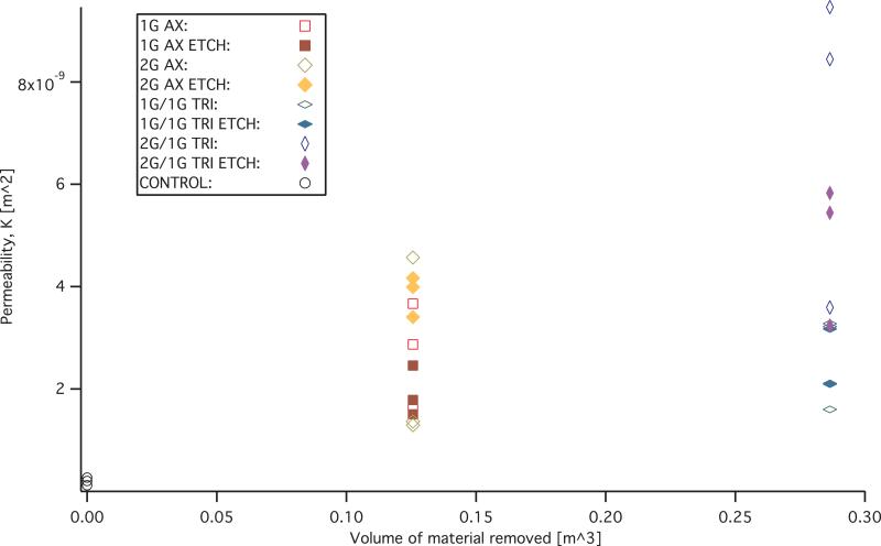
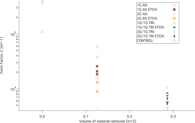
The measurements and FHDD algorithm fitted curves of the non-reticulated control samples are shown in figure 11. Permeability (K) and form factor (C) of each sample that was fitted with the FHDD equation was calculated from the pressure gradient measurements and the ranges are reported in Table 2. The calculated form factor (C) and permeability (K) values for the samples are displayed in figures 12 and 13 respectively. Form factor and permeability were plotted versus the idealized volume of material removed per cubic meter of solid polymer via mechanical reticulation, where the idealized volume of material removed was determined from the volume of the nitinol pins multiplied by the punch pattern. The sum of the volume of the nitinol pins was subtracted from a 1 m3 solid volume of polymer for the different reticulation patterns. Non-reticulated control samples correspond to 0.0 m3, uni-axial is 0.126 m3, tri-axial is 0.286 m3 of material removed per m3.
Figure 11.
Pressure gradient measurements of the non-reticulated control SMP foam samples.
Table 2.
Range of calculated Permeability (K) and Form factor (C) values of the cases tested.
| Permeability, K (m2) | Form factor, C (m−1) | |||
|---|---|---|---|---|
| Sample Type | min | max | min | max |
| 1 g Uni Axial | 1.64E-09 | 3.67E-09 | 1.67E+04 | 5.92E+04 |
| 1 g Uni Axial and Etch | 1.51E-09 | 2.46E-09 | 1.85E+04 | 2.59E+04 |
| 2 g Uni Axial | 1.29E-09 | 4.57E-09 | 4.25E+03 | 1.52E+04 |
| 2 g Uni Axial and Etch | 3.41E-09 | 4.17E-09 | 8.96E+03 | 1.32E+04 |
| 1 g/1 g Tri Axial | 1.60E-09 | 3.28E-09 | 4.63E+03 | 5.92E+03 |
| 1 g/1 g Tri Axial and Etch | 2.09E-09 | 3.17E-09 | 5.71E+03 | 8.38E+03 |
| 2 g/1 g Tri Axial | 3.59E-09 | 9.46E-09 | 4.25E+03 | 1.07E+04 |
| 2 g/1 g Tri Axial and Etch | 3.24E-09 | 5.83E-09 | 5.35E+03 | 6.66E+03 |
| Control | 1.18E-10 | 2.68E-10 | 1.10E+05 | 3.96E+05 |
Figure 12.
Permeability (K) versus estimated material removed from the foam via mechanical reticulation.
Figure 13.
Form factor versus estimated material removed from the foam via mechanical reticulation.
It was shown that all reticulated samples were an order of magnitude higher than the control samples in permeability and an order of magnitude lower in form factor.
3.5. In vivo vascular occlusion
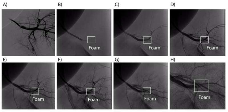
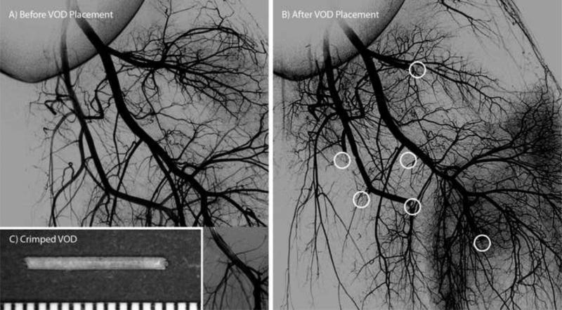
The uni-axial reticulated foam had an average occlusion time of 90 ± 11s and the tri-axial reticulated foam had an average occlusion time of 128 ± 77s. Figure 10 illustrates VOD deployment and subsequent vascular occlusion of a tri-axially reticulated VOD. Figure 11 shows angiograms of all treated vessels before VOD implantation and after vessel occlusion. On average the uni-axial reticulated foam induced faster occlusion that the tri-axial reticulated foam. This result is not unexpected since blood flow is likely impeded more by the less reticulated foam, potentially resulting in more rapid clotting. However, the large deviation of the occlusion time for the tri-axial reticulated foams, as well as the 30-s interval between contrast injections, prevents reaching a definitive conclusion on the effect of extent of reticulation on occlusion time; further study is required.
Figure 10.
Average compressive engineering stress vs. engineering strain for the foams reticulated according to Table 1. Each curve is an average of n stress-strain measurements.
4. Conclusions
Previously we have demonstrated that our SMP foams are biocompatible in vivo, when implanted into a porcine aneurysm model3. Though excellent healing was observed, these foams possessed a predominantly closed-cell structure, which likely limits the amount of blood flow allowed to percolate through the material and may delay or inhibit optimal healing in vivo. Reticulation may enhance application of these materials as an aneurysm filling or other vascular occlusion device. This study looked only at mechanical reticulation of these foams for vascular occlusion. These mechanically reticulated devices had membranes that were punctured, rather than completely removed. This may have increased their ability to act as an occlusion device due to greater surface area in contact with blood, relative to completely reticulated, or foams that have open windows between individual pore cells. However, further comparison to such materials would need to be made before conclusive statements can be made about the difference in occlusion rates between mechanically reticulated foams and foams reticulated via alternative methods.
We developed a method for non-destructive mechanical reticulation of ultra low density SMP foam by using a gravity-driven floating nitinol pin array coupled with vibratory agitation of the foam. Appropriate pin masses and agitation amplitude were identified to enable the desired level of reticulation. We focused on mechanical reticulation in different axes, versus changing the pin density of the array, to adjust the level of reticulation, and investigated chemical etching of the materials post reticulation.
Visually, there appeared to be a tradeoff of puncturing membranes, or membrane damage created as a function of mass, by down selecting to two and one gram pins for the preliminary detailed studies in the axial direction of puncture. In other words, the channels of the two gram pins appear to be less tortuous compared to the one gram pins when punched parallel to the axis of foaming, and therefore make a more direct path during reticulation. The less direct path, taken by the lower mass pins during reticulation, results in a less permeable sample. This is most likely due to the increase in surface area for which the fluid must interact with during the measurements of the pressure differential across the samples. Permeability measurements appear to confirm this statement as was evident by the majority of the two gram reticulated samples measured having a higher permeability, K values and lower form factor, C values.
However, the permeability and form factor values overlap for all of the uni axial cases and tri axial cases making definitive statements about the difference between cases of reticulation difficult. The data for the permeability shows that uni axial and tri axial reticulation increased the permeability for all cases compared to the control samples tested. However, the calculated permeability for all tri axial cases overlap and surpass the uni axial cases of reticulated foams. This may be due to the materials heterogeneous nature, which exhibit different pore cell densities even within the same batch. The overlap in calculated permeability may also be a result of the mechanical reticulation. The mechanical reticulation system was designed to be non-destructive and leave struts intact. In order to achieve this goal some of the pins do not reticulate the entire thickness for every instance of reticulation. The nitinol pins also deflect as they puncture the materials, making the pathways diverge away from a straight trajectory. Both of these results would cause variation in the amount of removal of membranes from sample to sample.
Overall, mechanical reticulation resulted in a reduced elastic modulus, but did not impede shape memory behavior as demonstrated by the in vitro delivery and in vivo occlusion tests. The modulus was lower for foams reticulated in multiple axes compared to a single axis. Supplemental chemical etching was not mechanically detrimental and for the axial cases tended to slightly increase the elastic modulus. Although the mechanical properties of the foams were decreased by all reticulation methods, the expansion in vivo was not affected. This is most likely due to the strong shape memory behavior and high stress recovery of these highly cross-linked polyurethane materials7. In other words, the mechanical properties of the bulk material were decreased by the reticulation methods, due to the loss in shear walls of the individual pores, but the ability of the structures to regain their primary shape via shape memory recovery should not be greatly affected unless there were damage to the struts of the foam. The shape memory properties should remain intact due to the struts, or main architecture of the material remaining unaffected by the reticulation, even if they are slightly less in recovery strength or take longer to recover. In addition, when the material is exposed to an aqueous environment in vivo, the materials may also be absorbing water from the environment and this may aid in the expansion to fill the vessel12, and this effect may surpass any loss in mechanical properties due to reticulation.
The reticulated VODs were capable of achieving rapid vascular occlusion in an in vivo porcine model, indicating that SMP foam could be used as a device not only to fill aneurysms, but to also occlude patent vessels under arterial pressure. It was shown that on average the less reticulated the VOD, the faster the occlusion time. However, further study is needed to definitively conclude that occlusion time is affected by level of reticulation. While we hypothesize that predominantly open-cell foams may enhance the aneurysm healing response compared to predominantly closed-cell foams due to the increased pathways for blood flow and cell migration, further work must be done to assess the healing response of reticulated foams.
Highlights.
- Non-destructive method for disrupting cell membranes (reticulating) of closed cell shape memory polymer foam.
- Reticulated foams used as a vascular occlusion devices in vivo.
- Reticulation reduced stiffness, but did not impede shape memory behavior.
- Reticulation increased permeability and decreased form factor of the material.
Figure 14.
In vivo deployment of a tri-axial reticulated foam: A) pre-deployment digital subtraction angiogram, B) guidewire ejection of the foam from the catheter (no contrast used), C G) contrast enhanced angiograms acquired after deployment at 30-s intervals, H) close up view of the fifth contrast enhanced angiography performed after deployment. Complete occlusion of the parent vessel is evident in (G) and (H), 165 s after delivery.
Figure 15.
Angiograms acquired (A) before implantation of the SMP foam VODs and (B) after vessel occlusion occurred. A separate angiogram showing the distal portion of one of the treated vessels is overlaid in (A). White circles indicate the locations of the SMP foam VODs in (B). (C) Compressed vascular occlusion device (scale divisions in mm).
Acknowledgments
This work was supported by the National Institutes of Health/National Institute of Biomedical Imaging and Bioengineering Grant R01EB000462 and partially performed under the auspices of the U.S. Department of Energy by Lawrence Livermore National Laboratory under Contract DE-AC52-07NA27344. The authors would like to thank Carl Johnson and Todd Landsman for their assistance in fabrication of the reticulation devices.
Abbreviations
- VOD
vascular occlusion device
- SMP
shape memory polymer
- RO
reverse osmosis
- LV-SEM
low vacuum scanning electron microscopy
Footnotes
Publisher's Disclaimer: This is a PDF file of an unedited manuscript that has been accepted for publication. As a service to our customers we are providing this early version of the manuscript. The manuscript will undergo copyediting, typesetting, and review of the resulting proof before it is published in its final citable form. Please note that during the production process errors may be discovered which could affect the content, and all legal disclaimers that apply to the journal pertain.
References
- 1.Bederson JB, Connolly ES, Batjer HH, Dacey RG, Dion JE, Diringer MN, Duldner JE, Harbaugh RE, Patel AB, Rosenwasser RH. Guidelines for the management of aneurysmal subarachnoid hemorrhage. Stroke. 2009;40(3):994–1025. doi: 10.1161/STROKEAHA.108.191395. [DOI] [PubMed] [Google Scholar]
- 2.Cebral JR, Mut F, Weir J, Putman C. Quantitative characterization of the hemodynamic environment in ruptured and unruptured brain aneurysms. American Journal of Neruroradiology. 2011;32:145–151. doi: 10.3174/ajnr.A2419. [DOI] [PMC free article] [PubMed] [Google Scholar]
- 3.Rodriguez JN, Clubb FJ, Wilson TS, Miller MW, Fossum T, Hartman J, Tuzun E, Singhal P, Maitland DJ. In vivo response to an implanted shape memory polyurethane foam in a porcine aneurysm model. Journal of Biomedical Materials Research Part A. 2013 doi: 10.1002/jbm.a.34782. http://dx.doi.org/10.1002/jbm.a.34782. [DOI] [PMC free article] [PubMed]
- 4.Rodriguez JN, Yu YJ, Miller MW, Wilson TS, Hartman J, Clubb FJ, Gentry B, Maitland DJ. Opacification of shape memory polymer foam designed for treatment of intracranial aneurysms. Annals of Biomedical Engineering. 2012;40(4):883–97. doi: 10.1007/s10439-011-0468-1. [DOI] [PMC free article] [PubMed] [Google Scholar]
- 5.Kipshidze N, Sadzaglishvili K, Panarella M, Elias A, Rivera MHS, Virmani R, Leon MB. Evaluation of a novel endoluminal vascular occlusion device in a porcine model: early and late follow-up. Journal of Endovascular Therapy. 2005;12(4):486–494. doi: 10.1583/05-1543.1. [DOI] [PubMed] [Google Scholar]
- 6.Rhee JY, Trocciola SM, Dayal R, Lin S, Chaer R, Kumar N, Mousa A, Bernheim J, Christos P, Prince M. Treatment of type II endoleaks with a novel polyurethane thrombogenic foam: Induction of endoleak thrombosis and elimination of intra-aneurysmal pressure in the canine model. Journal of Vascular Surgery. 2005;42(2):321–8. doi: 10.1016/j.jvs.2005.04.043. others. [DOI] [PubMed] [Google Scholar]
- 7.Singhal P, Rodriguez JN, Small W, Eagleston S, Van de Water J, Maitland DJ, Wilson TS. Ultra low density and highly crosslinked biocompatible shape memory polyurethane foams. Journal of Polymer Science, Part B: Polymer Physics. 2012;50(10):724–737. doi: 10.1002/polb.23056. [DOI] [PMC free article] [PubMed] [Google Scholar]
- 8.Gent AN, Rusch KC. Viscoelastic behavior of open-cell foams. National Academy of Sciences - National Reseach Council; Natick, Massachussetts: Apr 13-15, 1966. pp. 42–51. 1966. [Google Scholar]
- 9.Blair EA. Cell Structure: Physical Property Relationships in Elastomeric Foams. National Academy of Sciences, National Research Council; Natick, Massachussetts: Apr 13-15, 1966. pp. 143–152. 1966. [Google Scholar]
- 10.Singhal P, Boyle A, Brooks ML, Infanger S, Letts S, Small W, Maitland DJ, Wilson TS. Controlling the Actuation Rate of Low-Density Shape-Memory Polymer Foams in Water. Macromolecular Chemistry and Physics. 2013;214(11):1204–1214. doi: 10.1002/macp.201200342. [DOI] [PMC free article] [PubMed] [Google Scholar]
- 11.Geertsma J. Estimating the Coefficient of Inertial Resistance in Fluid Flow Through Porous Media. Society of Petroleum Engineers. 1974;14:445–450. [Google Scholar]
- 12.Yu Y- J, Hearon K, Wilson TS, Maitland DJ. The effect of moisture absorption on the physical properties of polyurethane shape memory polymer foams. Smart Materials and Structures. 2011;20(085010):6. doi: 10.1088/0964-1726/20/8/085010. [DOI] [PMC free article] [PubMed] [Google Scholar]


