Abstract
Centrifugal microfluidic platforms have emerged as point-of-care diagnostic tools. However, the unidirectional nature of the centrifugal force limits the available space for multi-stepped processes on a single microfluidics disc. To overcome this limitation, a passive pneumatic pumping method actuated at high rotational speeds has been previously proposed to pump liquid against the centrifugal force. In this paper, a novel micro-balloon pumping method that relies on elastic energy stored in a latex membrane is introduced. It operates at low rotational speeds and pumps a larger volume of liquid towards the centre of the disc. Two different micro-balloon pumping designs have been developed to study the pump performance and capacity at a range of rotational frequencies from 0 to 1500 rpm. The behaviour of the micro-balloon pump on the centrifugal microfluidic platforms has been theoretically analysed and compared with the experimental data. The experimental data shows that, the developed pumping method dramatically decreases the required rotational speed to pump liquid compared to the previously developed pneumatic pumping methods. It also shows that within a range of rotational speed, desirable volume of liquid can be stored and pumped by adjusting the size of the micro-balloon.
1. Introduction
The centrifugal microfluidic platform also known as CD-like microfluidic is an automated lab-on-a-disc platform (LOD) that relies on the centrifugal force to manipulate the liquid movement between the micro-chambers through micro-channels. The advantageous features of portability, disposability and full automation in these platforms have led to the research of various aspects of the centrifugal microfluidics for novel (ideal or efficient) point of care diagnostic (POC)1–6. Over the last decade, various centrifugal microfluidic designs have replicated standard medical diagnostics techniques such as the enzyme-linked immunosorbent assay (ELISA)7 and polymerase chain reaction (PCR)8. However, technology faces a severe implementation challenge due to the unidirectional nature of the centrifugal force, limiting the number of possible microfluidic networks which are available for complex integrated assays9. One way to implement more fluidic functions on a centrifugal microfluidics is to provide a mechanism that pumps liquid back to the disc centre.
In recent years, a handful of fluid manipulating techniques have been introduced to overcome unidirectional fluid flow on the centrifugal microfluidics. An initial study by Robert Gorkin et al.9 used a pneumatic compression chamber to pump liquid over a short distance toward the disc centre. Steffen Zehnle et al.10 connected a narrow inlet and a wider outlet to a compression chamber and has used the difference between their hydrodynamic resistance to pump a large amount of liquid back towards the disc centre. In another study by Garcia Cordero et al.11, hydrophilic capillary action was used to manipulate the flow direction on the disc. However, these techniques are limited either to the distance or the amount of liquid they can pump toward the disc centre. Moreover building enough pneumatic energy to pump liquid toward centre of the disc requires high rotational speed which may prematurely burst any passive valves that may be on the centrifugal microfluidics or and making hydrophilic capillaries requires complex surface modification procedures.
An ideal pumping solution that enables the implementation of multi-stepped or complex assays would be able to move a large volume of liquid while making efficient use of the disc space. To meet this requirement, a few studies have been conducted by various researchers. A study by Stefan Haeberle et al.12 employed a polydimethylsiloxane (PDMS) membrane pump that uses externally excited permanent magnets for flexing the membrane to inject air into a connected fluidic network to transfer liquid back to towards the disc centre. In a different pneumatic based study by Kong and Salin13, an external source of compressed air is used instead. However, in both studies, air from the surroundings is used for pumping the liquid. A major drawback of these pneumatic based studies is that there is a possibility of contamination of samples and reagents in the microfluidic process. In order to manipulate trapped air inside centrifugal microfluidics, Kameel Abi-Samra et al.14 and Thio et al.15 employed external heating source to heat air chambers and therefore utilized air expansion inside microfluidic system to pump liquid toward the disc centre. Drawback of these implementations is the added external features such as externally actuated magnet, air source or external heating source, which increase the complexity and cost of the system.
We introduce a novel technique, called latex micro-balloon pumping, which is easy to fabricate, control and integrate into the centrifugal microfluidic platforms. It is capable of propelling the liquid back to the disc centre without performing surface treatments or using external actuators. The micro-balloon pump is fabricated simply by integrating a highly flexible latex film onto the CD-like platform. This novel latex micro-balloon pump operates at low rotational speeds i.e., less than 1500 rpm and avoid external contaminants. It pumps predictable volume of liquid i.e., larger volume than conventional pneumatic methods to the expected distance from the disc centre. As one of the possible applications, we demonstrate siphon activation using the micro-balloon pump. To illustrate the suitability of using latex, we present a comparison between latex and the more commonly used PDMS as a flexible membrane.
2. Methods and materials
2.1. Micro-balloon pumping mechanism
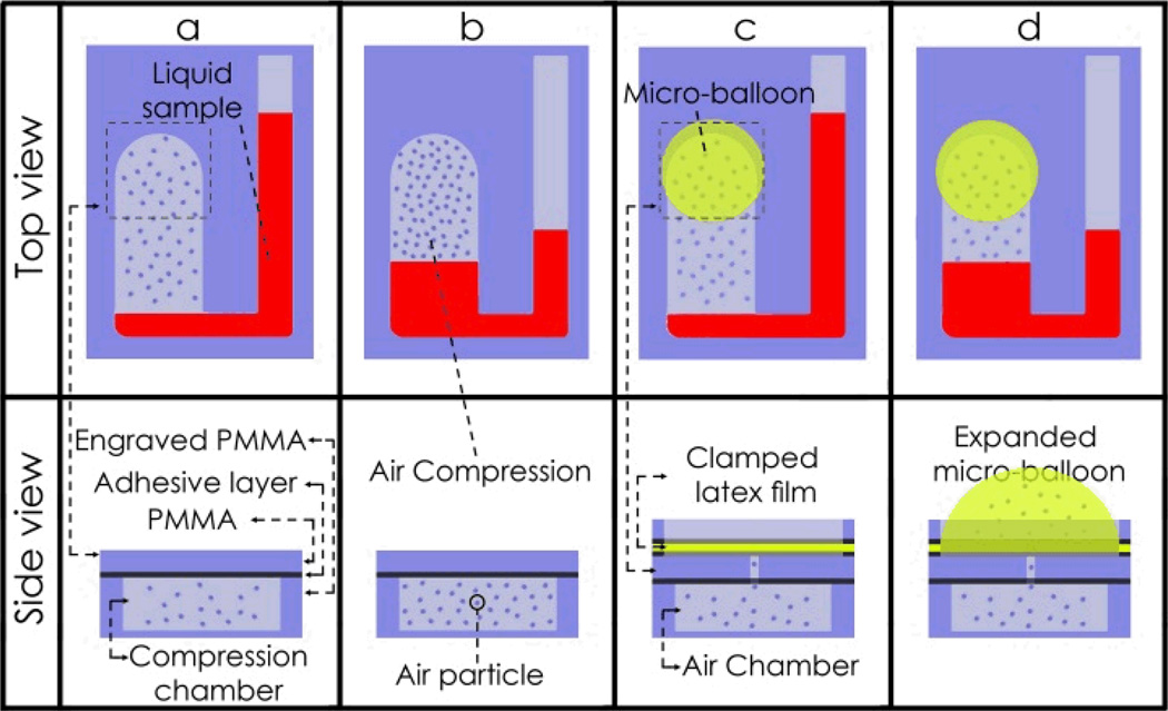
In order to achieve a holistic overview of the micro-balloon function in the centrifugal microfluidic, platforms we must compare a conventional pneumatic pumping method with the micro-balloon pumping technique. In the static pneumatic pumping method first introduced by Robert Gorkin et al. 9 trapped air in a sealed chamber prevents liquid from entering the chamber when the rotational speed is low i.e. low centrifugal force acting on the liquid (see Fig. 1a). At higher rotational speeds i.e. when a greater centrifugal force is acting on the liquid, the liquid is forced into the sealed chamber and compresses the trapped air (see Fig. 1b). This compression results in the pressurization of the trapped air in the sealed chamber, which acts as a kinetic energy storage device. When the rotational speed is reduced, the stored kinetic energy in the compressed air pumps the liquid back out of the sealed chamber. However, to effectively compress the air, high rotational speeds of 6000 to 7000 rpm is required, and this could prematurely burst any passive valves that may be on the disc.
Fig. 1.
Schematic of conventional pneumatic pumping and latex micro-balloon pumping. a Static pneumatic pumping before liquid enters the compression chamber, and b after liquid enters the compression chamber and it compresses the air. c latex micro-balloon before liquid enters the air chamber, and d after liquid enters the air chamber, it pushes against the trapped air inside the chamber and expands the micro-balloon.
To achieve the equivalent kinetic energy without operating at high rotational speeds, we use the elastic energy in an inflated micro-balloon, instead of using compressed air, by bonding a highly elastic micro-balloon to the perforated air chamber (see Fig. 1c). When the rotational speed is gradually increased, the liquid is forced into the air chamber, and pushes the air into the micro-balloon. The micro-balloon expands to accommodate the air displaced from the air chamber (see Fig. 1d). Therefore, the expanded micro-balloon acts as the kinetic energy storage vault. As in the case of static pneumatic pumping, when the rotational speed is reduced, the stored kinetic energy of the expanded micro-balloon pushes the stored air back into the air chamber, which pushes the liquid out of the chamber. This method effectively reduces the high rotational speed required for the conventional pneumatic technique (i.e., using a rigid compression chamber) to pump liquid towards the disc centre.
2.2. Micro-balloon material
Before conducting the experiment, a brief study of materials helped us to decide on the suitability of latex as compared to a silicone elastomer for fabrication of micro-balloons. Polydimethylsiloxane (PDMS) is a silicone elastomers, which due to its excellent mechanical and chemical properties, has been extensively used in advanced microfluidic platforms.16–23 PDMS is mainly used for fabrication of micro-pumps,24–26 micro-bioreactor,27, 28 micro-valves16, 26, 29–32 and etc. For instance, Stefen Heaberle et al.12 employed external permanent magnets to fluctuate a PDMS film and inject air bobbles into a connected microfluidic network. Latex films have also been used in microfluidic systems where biocompatible balloons,33,34 micro-valves,16,26,29–32,59 micro-pumps24–26, 35–38 and etc. were needed. Likewise to PDMS, latex has excellent chemical and physical properties such as chemical inertness, biocompatibility, high elasticity, thermal and electrical insulation36 and therefore enable wide range of techniques and application in microfluidic systems.39–42 Some of the characteristics and applications of PDMS and latex are listed in Table 1. Both the latex and PDMS films are highly transparent which makes them excellent materials to be implemented in microfluidic platforms. In addition, latex films have higher elasticity in comparison to PDMS films. The Young’s modulus of both latex and PDMS with thickness of 220 µm is 1.2MPa and 3.1MPa, respectively.39 In term of permeability, both the latex and PDMS films are liquid impermeable, however PDMS films due to their high gas permeability are more suitable for application in which aeration is required.43, 44 The oxygen permeability of PDMS at room temperature is 21 greater than natural latex.45, 46 Low gas permeability allows preserving the trapped air in the system and high elasticity lead to an efficient conversion of the kinetic energy to elastic energy, and conversely. Considering the higher elasticity and lower gas permeability of latex, in this study the latex film has been selected to make elastic micro-balloons in the centrifugal microfluidic platforms.
Table 1.
Brief comparison between the latex and PDMS film
| Property | L/P | Characteristics | Applications | |
|---|---|---|---|---|
| Optical | Latex PDMS |
Highly transparent >90% | Optical detection at wide range of wavelength | |
| Electrical | Latex PDMS |
Insulator breakdown voltage |
107-108 V/m47 2×10⁷ V/m49 |
Leads to fabricate embedded circuits and intentional breakdown to open connections48 |
| Biocompatibility | Latex PDMS |
Biocompatible Excellent Biocompatible |
Drug delivery, catheter, balloon angioplasty33,34. Wide range of applications in vivo50–53 |
|
| Permeability | Latex PDMS |
Water vapour impermeable54, 55 High gas permeable57, 58 |
Barrier for packing or sealing, also gas and liquid separation56 Supply oxygen to the cells 52 and gas permeation pumps43, 44. |
|
| Elasticity | Latex PDMS |
E- 1.2 to 3.1 MPa39 E- 1.6 to 11 MPa39 |
Micro valve and Micro-pumping systems39, 40 Micro valve16, 26, 29–32, 59and Micro-pumping systems24–26, 35–38 |
|
Note: Latex and PDMS films have wide range of elasticity the mentioned values are a close range of elasticity of conventional films
2.3. Centrifugal microfluidics platform fabrication
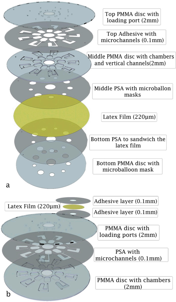
CD-like microfluidic platforms were fabricated with either a seven layer design, or a three layer design. In the first design the latex membrane covers the whole disc. The cut-outs in the layers below the latex allows for ballooning action when needed (see Fig. 2a). In the second design latex balloons are only placed on the disc where ballooning is required (see Fig. 2b). Both types of the introduced designs contain multiple layers of Polymethyl methacrylate (PMMA) discs, pressure sensitive adhesive (PSA) film layers and one latex film layer (0.22mm thickness natural latex film, by GBA Corporation Sdn. Bhd, Malaysia). A Computer Numerical Control (CNC) machine (model Vision 2525, by Vision Engraving & Routing Systems, USA) is used for engraving and cutting the micro-features such as the venting and loading holes, channels, micro-balloon masks, and chambers in the PMMA discs. A cutter plotter machine (model PUMA II, by GCC, Taiwan) is used to cut the necessary micro-features in the PSA films. The layers are aligned and pressed together to form a micro-balloon microfluidic system.
Fig. 2.
Schematics showing assemblies of CD-like microfluidic platforms consisting of PMMA, PSA layers and latex film; a Fabricating arrays of micro-balloon by a single fabrication process (seven layer design). b Fabricating a single micro-balloon (three layer design).
Fig. 2a shows the breakdown of the seven layer disc, comprised of three PMMA discs (each 2 mm thickness), three PSA layers (each 100 µm thickness) and a featureless latex layer (220 µm thickness) covering the whole disc area. The top PMMA disc contains only venting and loading holes, the middle layer contains the microfluidic features, while the bottom layer contains only the cut-out masks matching the sizes of the required micro-balloons. The top layer is first bond to the middle PMMA disc with a PSA layer with the venting and loading holes, chambers, and channel features cut out. Two PSA layers with cut masks (identical to the middle PMMA disc) are then used to sandwich the latex film between the middle and bottom PMMA disc. Fig. 2b shows the breakdown of the three layers disc comprising of two PMMA discs (each 2 mm thickness) and one PSA layer (100 µm thickness). The micro-balloon pumps in this case are fabricated individually from 2 layers of PSA (100 µm thickness) and a layer of latex (220 µm thickness). The latex layer is sandwiched between two PSA layers having the micro-balloon shape. The sandwiched latex is bonded onto the disc where required.
2.4. Centrifugal Microfluidics designs
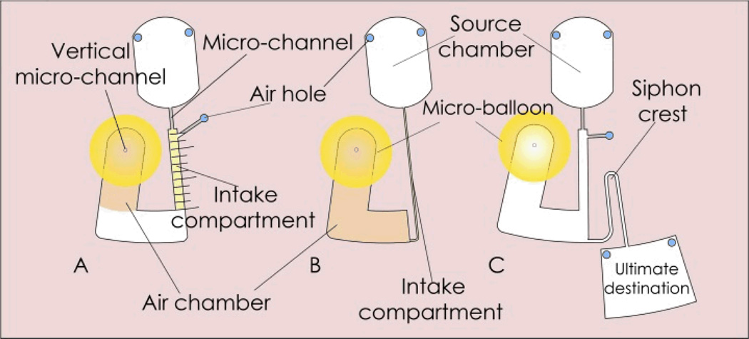
Different CD-like microfluidic designs were fabricated to demonstrate the implementation of the micro-balloon pump. Design A (see Fig. 3A) and Design B (see Fig. 3B) were utilized to perform an analytical evaluation of the pump performance. They demonstrate the effect of rotational frequency on the pumping strength and pumping capacity. Design C (see Fig. 3C) is employed to perform siphoning using micro-balloon pumping.
Fig. 3.
Microfluidic platform designs. Design A (on the left) contains a U-shaped destination chamber connected to the source chamber via a vertical micro-channel. The destination chamber comprises of an intake compartment and an air chamber attached with a micro-balloon. Design B (in the middle) consists of an air chamber attached with a micro-balloon. The air chamber is connected to the source chamber through an intake compartment. Design C (on the right) demonstrates the assisted siphon of liquid using design A.
2.4.1. Pump Strength
Design A (see Fig. 3A) consists of a source chamber and a sealed U-shaped destination chamber. The destination chamber comprises of an intake compartment and a perforated air chamber with an attached micro-balloon. The source chamber is connected to the intake compartment via a micro-channel. An air hole is placed on the top of the intake compartment (close to micro-channel) to ensure that the air is only trapped and displaced in the air chamber. To observe the strength of the micro-balloon pumping, 1 mm spaced markers are engraved on the disc surface over the intake compartment. The experiment is carried out by loading 70 µl of coloured deionized water into the source chamber. The rotational speed is gradually increased to 1500 rpm until entire liquid travels into the destination chamber. By reducing the rotational speed the liquid is pumped back towards the disc centre. In order to measure the micro-balloon pumping strength the corresponding rotational speed for each 1 mm advancement through the intake compartment is recorded during the experiment. The maximum volume of the liquid is pumped back when the rotational speed is decreased to zero and the latex film returns to its initial state. The experiment was repeated for micro-balloon sizes within the range of 3 mm to 5 mm radii. In order to compare the performance of micro-balloon pumping and pneumatic pumping, introduced by Robert Gorkin et al.,9 an experiment with the design A without implementation of micro-balloon was conducted and compared with the same micro-balloon design. The results are recorded in Fig. 6 and discussed in section 4 (Results and Discussion).
Fig. 6.
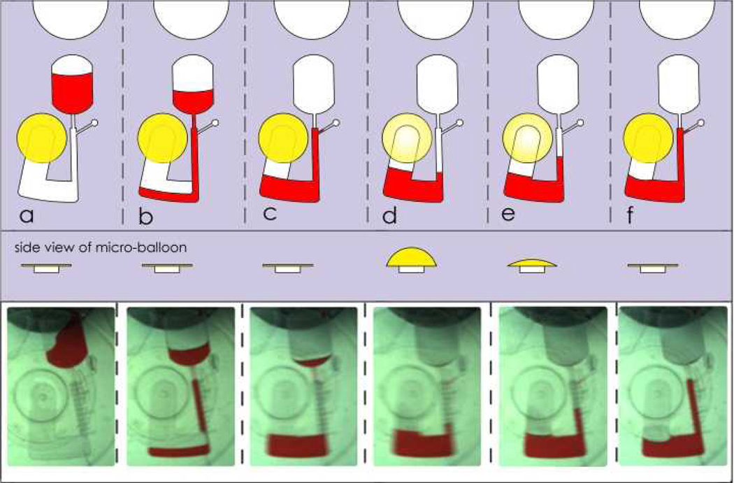
Schematic of micro-balloon micro-pumping analysis design. a the rotational frequency versus the liquid level in the intake compartment for three sizes of micro-balloons. b rotational the platform causes filling through the intake compartment. c continued filling traps air in the air chamber. d high centrifugal force causes continued of liquid transfer and expansion of the micro-balloon which allows near equalization of the liquid levels. e slowing the rotational speed reduces the centrifugal pressure, constricts the micro-balloon and liquid inside the intake compartment is pumped back towards centre of the disc. f when rotational speed is reduced to zero the micro-balloon is flattened (returned to its initial state) and liquid is pumped to the closest position to centre of the disc.
2.4.2. Pump Capacity
Design B (see Fig. 3B) consists of a source chamber and an air chamber. The source chamber is connected to the air chamber via an intake compartment that is connected to the bottom of the air chamber. In this design there is no air hole at the top of the intake compartment and the intake compartment is connected to the bottom of the air chamber. The connection of the intake compartment to the bottom of the air chamber allows using the whole air volume in the air chamber to expand the micro-balloon. The experiment was carried out by loading coloured deionized water samples ranging from 10 µL to 90 µL into the source chamber. In order to measure the micro-balloon capacity the rotational speed at which all liquid is drained from the source chamber is recorded. The experiment was repeated for a range of micro-balloon sizes with radii ranging from 3 mm to 5 mm. The results are recorded in Fig. 8 and discussed in Section 4 (Results and Discussion).
Fig. 8.
The rotational frequency versus the amount of stored liquid using design B (see Fig. 3b) for three different sizes of micro-balloons.
2.4.3. Assisted Siphon Priming
With design C (see Fig. 3C) we demonstrate how the siphon process can be accomplished without the need for high rotational frequencies or micro-channel surface modifications. Design C is the same as design A except that it has a siphon and an ultimate destination chamber. For siphons to be primed, the liquid in the intake compartment must pump beyond the siphon crest. In our demonstration, a 3 mm radius micro-balloon is installed in the air chamber. The experiment was carried out by loading 80 µL of coloured deionized water into the source chamber and spinning the disc up to 1400 rpm to transfer liquid to destination chamber. Rotational speed is gradually reduced and liquid is pumped toward the disc centre, until siphon actuated and the liquid entered to the ultimate destination.
3. Pumping analysis
In this section we theoretically describe the micro-balloon pumping mechanism to facilitate future implementations of this novel pumping technique in centrifugal microfluidics platform. In general, the behaviour of the micro-balloon pumping can be described in terms of changes of the liquid level in the intake compartment i.e., x=Ri - Ri0 (see Fig. 4). The liquid level in the intake compartment is resulted from the equilibrium of the hydrostatic pressure and the kinetic energy stored in the micro-balloon.
Fig. 4.
Figure showing parameters regarding to micro-balloon expansion volume and hydrostatic pressure when the disc is stopped and rotational. Ri0, Rc0, Ri, Rc are liquid plug distances from the disc centre in the intake compartment and air chamber when the disc is stopped and rotated, x and y are liquid level heights in the intake compartment and air chamber respectively. Micro-balloon expansion height (bulge height) is defined by z and rb is the Micro-balloon radius
Fig 4 shows the centrifugal microfluidic design that consists of a U-shaped chamber i.e., air chamber and intake compartment. Figure 4a shows the liquid level and the air trapped in the air chamber when the system is at rest. When the disc is spinning, due to the flexibility of the micro-balloon, the liquid level in the air chamber rises up, and the liquid level in the intake compartment goes down (see Fig 4. b). At this point, the micro-balloon expansion volume is equivalent to the amount of liquid entered the air chamber.
The hydrostatic pressure acted on the liquid column in the U-shaped chamber is given as 9:
| (1) |
where ρ is the liquid density, ω is the rotational frequency Rc, Ri are liquid levels in the air chamber and intake compartment, respectively. Substituting Rc, Ri with Rc0-y and Ri=Ri0-x in equation (1) yield 9:
| (2) |
where x and y are the respective changes in liquid levels in the intake compartment and the air chamber: x=Ri–Ri0 and y = Rc0–Rc as shown in Fig. 4. To simplify the pervious expression, we let the term (Rc0–y+(Ri0+x))(Rc0–y–(Ri0+x)) be denoted as φ(x). Equation (2) is simplified to:
| (3) |
The pressure P represented by equation (2) and (3) causes the expansion of the micro-balloon. When expanded, the pressure exerted by the micro-balloon Pb(z) can be expressed in terms of the micro-balloon bulge height and initial radius as follows60, 61:
| (4) |
where M is the bi-axial modulus of elasticity, t is the thickness of the latex film, rb is the initial micro-balloon radius, σ0 is the initial film stress, z is the bulge height (micro-balloon height), and C1, C2 are constants. The thin latex film bi-axial modulus of elasticity is defined as M=E/(1-ν) where E is the Young’s modulus of elasticity and ν the Poisson’s ratio.
To evaluate equation (4), the bulge height z of the micro-balloon should be determined. The bulge height is a result of the air displaced by the liquid in the air chamber. The relationship between the micro-balloon expansion volume (V) and the liquid level and cross-sectional areas of the compartments is defined as follows:
| (5) |
where x and y are the respective change in liquid levels in the intake and air chamber (see Fig. 4), and Si and Sc are the cross-sectional areas of the two compartments. Solving equation (5) allows us to determine the bulge height of the micro-balloon using either the volume change in the intake compartment (xSi) or the volume in the air chamber (ySi):
| (6) |
Equating (3) and (4) allows us to obtain a relationship between the liquid levels (indicated by φ(x)) and the rotational frequency of the disc:
| (7) |
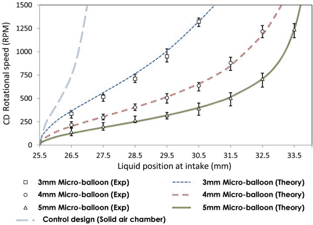
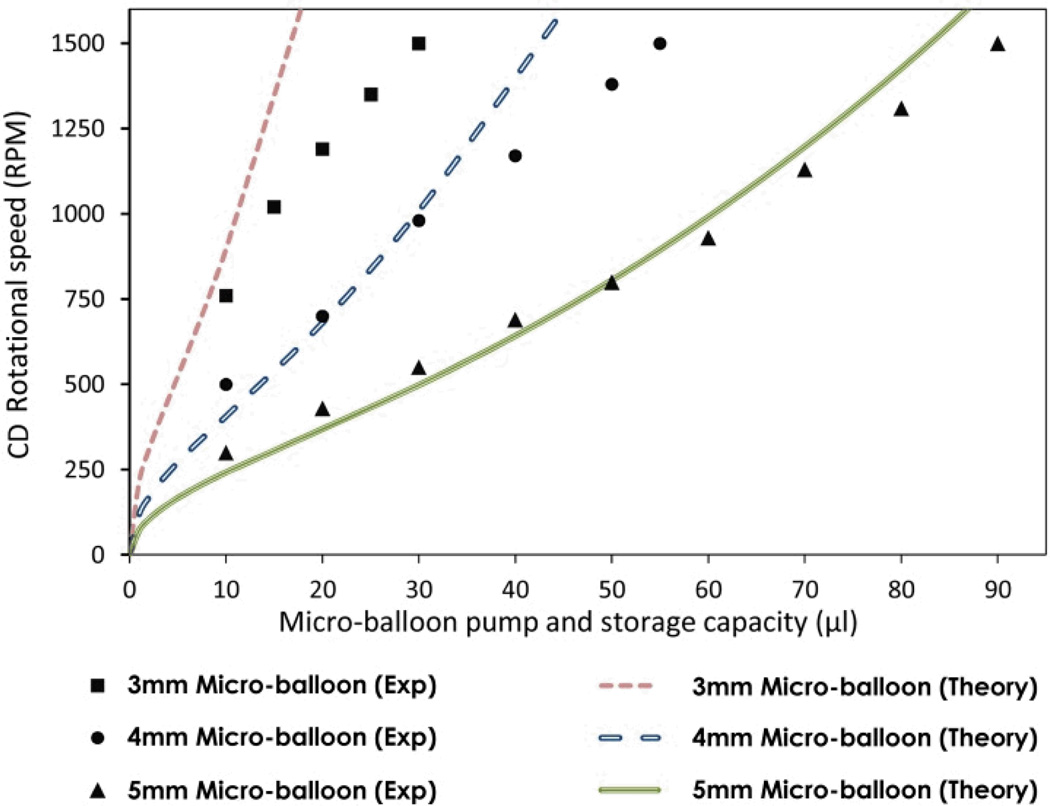
equations (6 and 7), have been compared with the experimental data for rotational frequencies from 0 to 1500 rpm. Fig. 6 shows the comparison between theoretical and experimental results for various micro-balloons. The parameters used for the evaluation of equation (7) are listed in Table 1. The use of equation (7) for calculating pumping capacity at various rotational frequencies was experimentally tested. Fig 8 shows a comparison between recorded values of pumping capacities and those calculated from the equation (7).
4. Results and discussion
4.1. Pump mechanism
This section describes the pump behaviour for various pump sizes and rotational frequencies. Two experiments based on Design A and B (see Fig. 3a and 3b) were carried out to determine the micro-balloon pumping strength and capacity under different rotational speeds.
4.1.1. Pump Strength
A step by step description of the experiments based on Design A (see Fig. 3A) is shown in Fig. 5. The experiment was carried out by loading liquid into the source chamber (see Fig. 5a) and spinning the disc until the liquid bursts into the destination chamber (see Fig. 5b). During filling the destination chamber, air escapes through the air hole. Once the liquid has reached the bottom of the air chamber (see Fig. 5c), air within the air chamber is trapped. The trapped air expands the micro-balloon with gradually increment of the rotational speed (see Fig. 5d). The rotational speed is increased until the liquid level at the intake compartment is nearly equalized to the liquid level at the air chamber. At this point, reducing the rotational speed causes the contraction of the micro-balloon. The displaced air due to the contraction of the balloon pumps the liquid towards the disc centre. The volume of the liquid pumped towards the disc centre is controlled by adjusting the rotational speed (see Fig. 5e).The micro-balloon returns to its relaxed state when the rotational speed is reduced to zero i.e., the maximum volume of the liquid is pumped towards disc centre (see Fig. 5f). Fig. 6 illustrates the corresponding rotational frequencies to the liquid level in the intake compartment. The experimental data for micro-balloon radii of 3-5 mm are compared with that of the control design and the theoretical expression (Eq. 7). The results show that the liquid level is proportional to the rotational speed, liquid volume and the micro-balloon size. For a constant liquid volume increasing the micro-balloon radius decreases the required range of rotational speed to pump the liquid. For instance, a 5 mm radius micro-balloon pumps larger volume of liquid in comparison with a 3 mm radius micro-balloon. All three different micro-balloons used in the experiment pump substantially larger volume of the liquid i.e., up to 5 times in comparison with the control design. in order To pump such volume of liquid with the conventional pneumatic pumping methods 6000-8000 rpm is required (see ref. 9).
Fig. 5.
Schematic of micro-balloon micro-pumping analysis design. a liquid is loaded. b rotational the platform causes filling through the intake compartment. c continued filling traps air in the air chamber. d high centrifugal force causes continued of liquid transfer and expansion of the micro-balloon which allows near equalization of the liquid levels. e slowing the rotational speed reduces the centrifugal pressure, constricts the micro-balloon and liquid inside the intake compartment is pumped back towards the centre of the disc. f when rotational speed is reduced to zero the micro-balloon is flattened (returned to its initial state) and liquid is pumped to the closest position to centre of the disc.
4.1.2 Micro-Balloon Pumping capacity
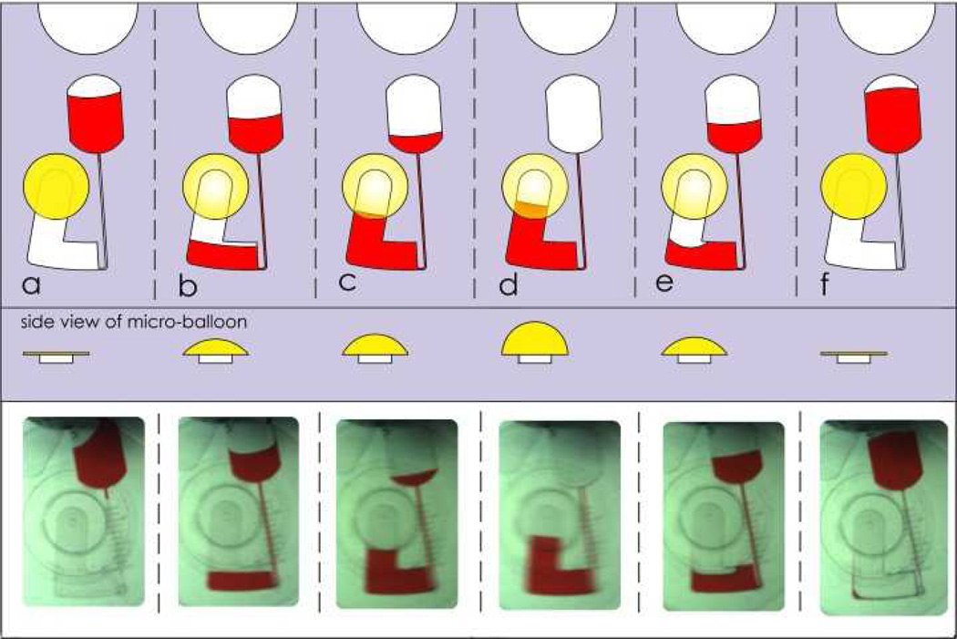
Stage by stage observation of the experiments based on design B(see Fig. 2) is shown in Fig. 7. Liquid is initially loaded into the source chamber (see Fig. 7a). The disc is spun to transfer liquid into the air chamber (see Fig. 7b). The lack of venting hole in the design causes air to travel from the air chamber to the micro-balloon at the instance the liquid enters to the air chamber. Increasing the rotational speed results in more liquid transfer into the air chamber (see Fig. 7c). The frequency at which the liquid is fully removed from the source chamber (see Fig. 7d) is recorded in Fig. 8. At this stage, the amount of liquid is equivalent to the capacity of the micro-balloon of that particular rotational frequency. To test the performance of the Micro-balloon, the rotational speed is gradually reduced (see Fig. 7e) to show that the stored liquid is fully pumped to the source chamber when the rotation speed is reduced to 0 rpm (see Fig 7f).
Fig. 7.
Schematic of micro-balloon micro-pumping. a Sample liquid is initially loaded into the source chamber. b The platform is then spun to burst the liquid from the source chamber into the air chamber. The absence of any vent hole in the air chamber forces the displaced air into the micro-balloon. c Increasing rotational speed results in higher centrifugal force and more volume of liquid is transferred to the air chamber. d All the liquid is transferred into the air chamber. e Reducing the rotational speed to lower levels result in micro-balloon contraction, this in return pumps the sample liquid back to the disc centre. f All the liquid is pumped back towards the disc centre to the source chamber.
It is clear from Fig 8 that the volume of liquid that can be stored is increases with the size of the micro-balloon. At a rotational speed of 1500 rpm, increasing the micro-balloon diameter from 3 mm to 5 mm increases the amount of stored liquid from 30µl to approximately 90µl. The theoretical results are in good agreement with the experimental results.
Adjusting the place where the intake compartment is connected to the air chamber determines the volume of liquid to be pumped back. The exact value of the liquid volume is important in various applications e.g., blood serum separation and collection.
4.2 Siphon actuation
On the centrifugal microfluidic platforms, siphoning is often employed to transfer liquid between two chambers in a multi-steps process. The examples include the blood serum separation and the transfer of liquid from the detection chamber to the waste chamber for an ELISA18, or the cascaded transfer of liquid between a series of chambers19. Current centrifugal platforms either utilize micro-channels surface modification or pneumatic pumping technique to implement siphon valves62–64. However, surface properties of polymers tend to return to its natural state over time and pneumatic pumping methods requires high rotational speeds.
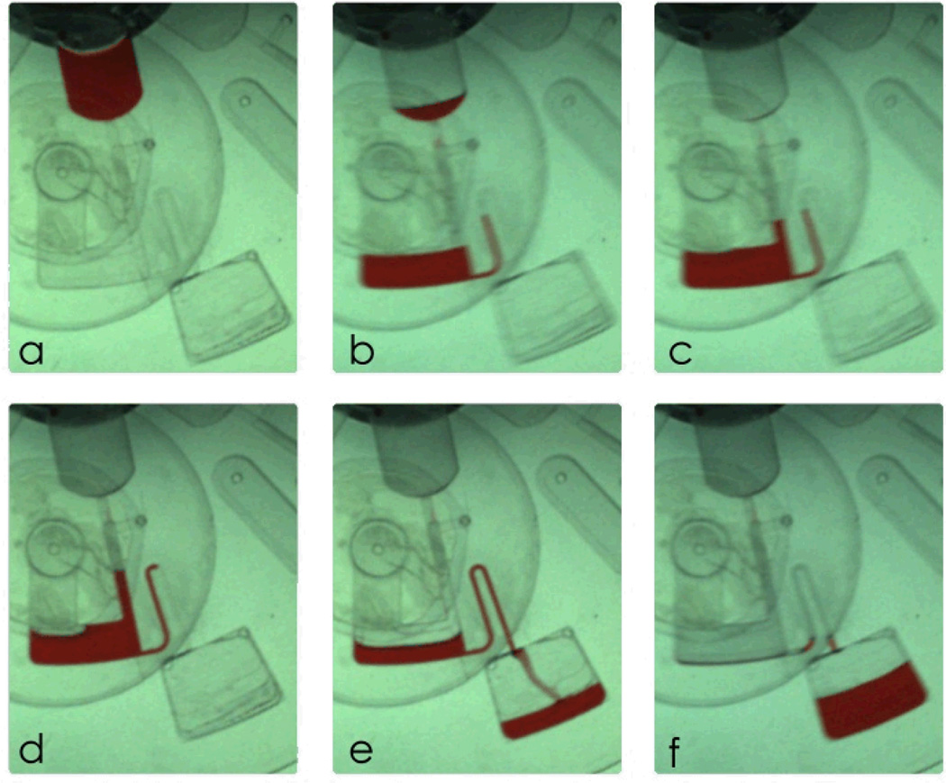
The inclusion of a micro-balloon onto the centrifugal microfluidics platform allows for siphon actuation without the need for surface treatment or air compression. The step by step process of siphon actuation using design C (see Fig. 2) is shown in Fig. 9.The source chamber is initially loaded with 80 µl of liquid (see Fig. 9a). The disc is gradually spun to transfer liquid from the source chamber into the destination chamber (see Fig. 9b) during which the micro-balloon inflates to store the air displaced. At rotational speed of 1400 rpm whole liquid is transferred to the destination chamber where liquid levels at both destination chamber and siphon channel are equal (see Fig. 9c). At this stage, the height of the liquid in the intake compartment does not reach the top of the siphon crest and therefore siphon doesn’t actuate. By gradually decreasing the rotational speed, the centrifugal pressure acting on the liquid decreases proportionally. Therefore, the micro-balloon pushes the displaced air back into the air chamber. The air displaced pumps the liquid up into the adjoining intake compartment and into the siphon channel (see Fig. 9d). Once the liquid level in the siphon channel reaches the top of the crest, the siphon is actuated and liquid is siphoned into the ultimate collection chamber (see Fig. 9e and 9f). The rotational speed at which this occurs in our experiment is as low as 580 + 10 rpm. Unlike conventional pneumatically activated siphoning which requires high rotational speed9, in our design, the siphoning operates at a low range of rotational speed. Another benefit of the micro-balloon assisted siphon is the ability to actuate the siphon under both hydrophobic and hydrophilic conditions.
Fig. 9.
schematic of siphon valve. a loading source chamber. b transferring liquid to the destination chamber by centrifugal force and trapping the air in the air chamber. c equalization of liquid levels at intake compartment and air chamber, and micro-balloon expansion. d decreasing the rotational speed cause micro-balloon contraction and pumps liquid in intake toward the disc centre. e when liquid level is higher than the siphon crest siphon activates and liquid sample transfers to ultimate destination. f slightly increasing the rotational frequency transfers whole liquid samples.
5. Conclusions
Unidirectional nature of fluids flow within centrifugal microfluidic platforms limits number of possible process steps before fluids reach to the rim of the disc. To overcome this limitation, we have presented a novel technique, called micro-balloon pumping. Micro-balloon pumping is based on displacement of trapped air to expand a highly elastic latex membrane and employ the stored elastic energy for pumping fluids. In comparison with other pumping methods geared to push fluids against centrifugal force, micro-balloon pumping does not require surface treatment, high rotational speed or any external actuators to create enough energy. The micro-balloon pumping compared to conventional pneumatic pumping techniques is able to pump larger volume of liquids at dramatically lower the range of rotational speed.
The micro-balloon pumping strength was modelled and the model was confirmed by analysing rotational speed versus pumping position for three different sizes of micro-balloons. The model can be used to predict pump capacity of each size of the micro-balloons. As a practical application of this novel pumping mechanism, we used micro-balloon to actuate siphons. Overall, the micro-balloon pumping is an efficient fluid propelling technique that enables more complex biochemical assays on centrifugal microfluidic platforms.
Table 2.
value of parameters used in analytical analysis
| Parameters | Value | Parameters | Value |
|---|---|---|---|
| rb | 3,4 and5mm | E | 1.2 MPa |
| Ri0 | 25.5 mm | ν | 0.48 |
| Rc0 | 36 mm | σ0(rb-3mm) | 0.06 MPa |
| t | 220 µm | σ0(rb-4mm) | 0.058 MPa |
| ρ | 1000 kg/m3 | σ0(rb-5mm) | 0.055 MPa |
| Si | 1.49 mm2 | Sc | 6.12 mm2 |
Acknowledgements
This research is supported by UM High Impact Research Grant UM-MOHE UM.C/625/1/HIR/MOHE/05 from the Ministry of Higher Education Malaysia, and University of Malaya Research Grant (UMRG: RG023/09AET).
MM would like to acknowledge support of the National Institute of Health (grant 1 R01 AI089541-01). MM also acknowledges support of WCU (World Class University)program (R32-2008-000-20054-0) through the National Research Foundation of Korea funded by the Ministry of Education, Science and Technology.
References
- 1.Garcia-Cordero JL, Barrett LM, O’Kennedy R, Ricco AJ. Biomedical microdevices. 2010;12:1051–1059. doi: 10.1007/s10544-010-9459-5. [DOI] [PubMed] [Google Scholar]
- 2.Haeberle S, Brenner T, Zengerle R, Ducrée J. Lab on a Chip. 2006;6:776–781. doi: 10.1039/b604145k. [DOI] [PubMed] [Google Scholar]
- 3.Lee BS, Lee YU, Kim H-S, Kim T-H, Park J, Lee J-G, Kim J, Kim H, Lee WG, Cho Y-K. Lab Chip. 2010;11:70–78. doi: 10.1039/c0lc00205d. [DOI] [PubMed] [Google Scholar]
- 4.Madou M, Zoval J, Jia G, Kido H, Kim J, Kim N. Annu. Rev. Biomed. Eng. 2006;8:601–628. doi: 10.1146/annurev.bioeng.8.061505.095758. [DOI] [PubMed] [Google Scholar]
- 5.Steigert J, Grumann M, Brenner T, Riegger L, Harter J, Zengerle R, Ducrée J. Lab Chip. 2006;6:1040–1044. doi: 10.1039/b607051p. [DOI] [PubMed] [Google Scholar]
- 6.Kazemzadeh A, Ganesan P, Ibrahim F, He S, Madou MJ. PloS one. 2013;8:e73002. doi: 10.1371/journal.pone.0073002. [DOI] [PMC free article] [PubMed] [Google Scholar]
- 7.Lai S, Wang S, Luo J, Lee LJ, Yang S-T, Madou MJ. Analytical chemistry. 2004;76:1832–1837. doi: 10.1021/ac0348322. [DOI] [PubMed] [Google Scholar]
- 8.Amasia M, Cozzens M, Madou MJ. Sensors and Actuators B: Chemical. 2011 [Google Scholar]
- 9.Gorkin R, Clime L, Madou M, Kido H. Microfluidics and Nanofluidics. 2010;9:541–549. [Google Scholar]
- 10.Zehnle S, Schwemmer F, Roth G, von Stetten F, Zengerleabc R, Pausta N. Lab on a Chip. 2012;12:5142–5145. doi: 10.1039/c2lc40942a. [DOI] [PubMed] [Google Scholar]
- 11.Garcia-Cordero JL, Basabe-Desmonts L, Ducrée J, Ricco AJ. Microfluidics and nanofluidics. 2010;9:695–703. [Google Scholar]
- 12.Haeberle S, Schmitt N, Zengerle R, Ducrée J. Sensors and Actuators A: Physical. 2007;135:28–33. [Google Scholar]
- 13.Kong MC, Salin ED. Analytical chemistry. 2010;82:8039–8041. doi: 10.1021/ac102071b. [DOI] [PubMed] [Google Scholar]
- 14.Abi-Samra K, Clime L, Kong L, Gorkin R, III, Kim T-H, Cho Y-K, Madou M. Microfluidics and nanofluidics. 2011;11:643–652. [Google Scholar]
- 15.Thio THG, Ibrahim F, Al-Faqheri W, Moebius J, Khalid NS, Soin N, Kahar MKBA, Madou MJ. Lab Chip. 2013 doi: 10.1039/c3lc00004d. [DOI] [PMC free article] [PubMed] [Google Scholar]
- 16.Beebe DJ, Moore JS, Yu Q, Liu RH, Kraft ML, Jo B-H, Devadoss C. Proceedings of the National Academy of Sciences. 2000;97:13488–13493. doi: 10.1073/pnas.250273097. [DOI] [PMC free article] [PubMed] [Google Scholar]
- 17.Anderson JR, Chiu DT, Wu H, Schueller OJA, Whitesides GM. Electrophoresis. 2000;21:27–40. doi: 10.1002/(SICI)1522-2683(20000101)21:1<27::AID-ELPS27>3.0.CO;2-C. [DOI] [PubMed] [Google Scholar]
- 18.Vollmer AP, Probstein RF, Gilbert R, Thorsen T. Lab on a Chip. 2005;5:1059–1066. doi: 10.1039/b508097e. [DOI] [PubMed] [Google Scholar]
- 19.Kaigala GV, Hoang VN, Stickel A, Lauzon J, Manage D, Pilarski LM, Backhouse CJ. Analyst. 2008;133:331–338. doi: 10.1039/b714308g. [DOI] [PubMed] [Google Scholar]
- 20.Cygan ZT, Cabral JT, Beers KL, Amis EJ. Langmuir. 2005;21:3629–3634. doi: 10.1021/la0471137. [DOI] [PubMed] [Google Scholar]
- 21.Kim MS, Yeon JH, Park JK. Biomedical Microdevices. 2007;9:25–34. doi: 10.1007/s10544-006-9016-4. [DOI] [PubMed] [Google Scholar]
- 22.Chung S, Sudo R, Mack PJ, Wan CR, Vickerman V, Kamm RD. Lab Chip. 2008;9:269–275. doi: 10.1039/b807585a. [DOI] [PubMed] [Google Scholar]
- 23.Tourovskaia A, Figueroa-Masot X, Folch A. Lab Chip. 2004;5:14–19. doi: 10.1039/b405719h. [DOI] [PubMed] [Google Scholar]
- 24.Pan T, McDonald SJ, Kai EM, Ziaie B. Journal of Micromechanics and Microengineering. 2005;15:1021. [Google Scholar]
- 25.Jeong OC, Park SW, Yang SS, Pak JJ. Sensors and Actuators A: Physical. 2005;123:453–458. [Google Scholar]
- 26.Grover WH, Skelley AM, Liu CN, Lagally ET, Mathies RA. Sensors and Actuators B: Chemical. 2003;89:315–323. [Google Scholar]
- 27.Ostrovidov S, Jiang J, Sakai Y, Fujii T. Biomedical microdevices. 2004;6:279–287. doi: 10.1023/B:BMMD.0000048560.96140.ca. [DOI] [PubMed] [Google Scholar]
- 28.Wu MH, Urban JP, Cui Z, Cui ZF. Biomedical microdevices. 2006;8:331–340. doi: 10.1007/s10544-006-9597-y. [DOI] [PubMed] [Google Scholar]
- 29.Go JS, Shoji S. Sensors and Actuators A: Physical. 2004;114:438–444. [Google Scholar]
- 30.Li N, Hsu CH, Folch A. Electrophoresis. 2005;26:3758–3764. doi: 10.1002/elps.200500171. [DOI] [PMC free article] [PubMed] [Google Scholar]
- 31.Takao H, Miyamura K, Ebi H, Ashiki M, Sawada K, Ishida M. Sensors and Actuators A: Physical. 2005;119:468–475. [Google Scholar]
- 32.Lagally ET, Lee S-H, Soh H. Lab on a Chip. 2005;5:1053–1058. doi: 10.1039/b505915a. [DOI] [PubMed] [Google Scholar]
- 33.Herculano RD, Alencar de Queiroz AA, Kinoshita A, Oliveira ON, Jr, Graeff CF. Materials Science and Engineering: C. 2011;31:272–275. [Google Scholar]
- 34.Balabanian CACA, Coutinho-Netto J, Lamano-Carvalho TL, Lacerda SA, Brentegani LG. Journal of Oral Science. 2006;48:201–205. doi: 10.2334/josnusd.48.201. [DOI] [PubMed] [Google Scholar]
- 35.Lagally ET, Emrich CA, Mathies RA. Lab Chip. 2001;1:102–107. doi: 10.1039/b109031n. [DOI] [PubMed] [Google Scholar]
- 36.Cosnier S, Szunerits S, Marks RS, Novoa A, Puech L, Perez E, Rico-Lattes I. Talanta. 2001;55:889–897. doi: 10.1016/s0039-9140(01)00498-2. [DOI] [PubMed] [Google Scholar]
- 37.Nagayama K. Colloids and Surfaces A: Physicochemical and Engineering Aspects. 1996;109:363–374. [Google Scholar]
- 38.Weibel DB, Siegel AC, Lee A, George AH, Whitesides GM. Lab on a Chip. 2007;7:1832–1836. doi: 10.1039/b714664g. [DOI] [PubMed] [Google Scholar]
- 39.Brask A, Snakenborg D, Kutter JP, Bruus H. Lab on a Chip. 2006;6:280–288. doi: 10.1039/b509997h. [DOI] [PubMed] [Google Scholar]
- 40.Zhang C, Xing D, Li Y. Biotechnology advances. 2007;25:483–514. doi: 10.1016/j.biotechadv.2007.05.003. [DOI] [PubMed] [Google Scholar]
- 41.Han A, Wang O, Graff M, Mohanty SK, Edwards TL, Han KH, Frazier AB. Lab on a Chip. 2003;3:150–157. doi: 10.1039/b302118a. [DOI] [PubMed] [Google Scholar]
- 42.Han KH, McConnell RD, Easley CJ, Bienvenue JM, Ferrance JP, Landers JP, Frazier AB. Sensors and Actuators B: Chemical. 2007;122:337–346. [Google Scholar]
- 43.Dittrich PS, Tachikawa K, Manz A. Analytical Chemistry. 2006;78:3887–3908. doi: 10.1021/ac0605602. [DOI] [PubMed] [Google Scholar]
- 44.Eddings MA, Gale BK. Journal of Micromechanics and Microengineering. 2006;16:2396. [Google Scholar]
- 45.Hillborg H. Loss and recovery of hydrophobicity of polydimethylsiloxane after exposure to electrical discharges. GRIN Verlag; 2012. [Google Scholar]
- 46.Hillborg H, Gedde U. Dielectrics and Electrical Insulation, IEEE Transactions on. 1999;6:703–717. [Google Scholar]
- 47.Braga M, Costa CAR, Leite CAP, Galembeck F. The Journal of Physical Chemistry B. 2001;105:3005–3011. [Google Scholar]
- 48.McDonald JC, Steven J, Whitesides GM. Analytical chemistry. 2001;73:5645–5650. doi: 10.1021/ac010631r. [DOI] [PubMed] [Google Scholar]
- 49.McDonald JC, Whitesides GM. Accounts of chemical research. 2002;35:491–499. doi: 10.1021/ar010110q. [DOI] [PubMed] [Google Scholar]
- 50.Whitesides GM. Nature. 2006;442:368–373. doi: 10.1038/nature05058. [DOI] [PubMed] [Google Scholar]
- 51.Bélanger MC, Marois Y. Journal of biomedical materials research. 2001;58:467–477. doi: 10.1002/jbm.1043. [DOI] [PubMed] [Google Scholar]
- 52.Leclerc E, Sakai Y, Fujii T. Biomedical microdevices. 2003;5:109–114. [Google Scholar]
- 53.De Jong J, Lammertink R, Wessling M. Lab Chip. 2006;6:1125–1139. doi: 10.1039/b603275c. [DOI] [PubMed] [Google Scholar]
- 54.Grubauer G, Elias PM, Feingold KR. Journal of Lipid Research. 1989;30:323–333. [PubMed] [Google Scholar]
- 55.Arda E, Pekcan Ö. Polymer. 2001;42:7419–7428. [Google Scholar]
- 56.Stephen R, Ranganathaiah C, Varghese S, Joseph K, Thomas S. Polymer. 2006;47:858–870. [Google Scholar]
- 57.Mark JE. Polymer data handbook. New York: Oxford University Press; 2009. [Google Scholar]
- 58.Merkel T, Bondar V, Nagai K, Freeman B, Pinnau I. Journal of Polymer Science Part B: Polymer Physics. 2000;38:415–434. [Google Scholar]
- 59.Lagally ET, Lee SH, Soh H. Lab on a Chip. 2005;5:1053–1058. doi: 10.1039/b505915a. [DOI] [PubMed] [Google Scholar]
- 60.Hohlfelder RJ. Bulge and blister testing of thin films and their interfaces. 1999 [Google Scholar]
- 61.Gad-el-Hak M. MEMS: Design and fabrication. CRC press; 2010. [Google Scholar]
- 62.Ducrée J, Haeberle S, Lutz S, Pausch S, Von Stetten F, Zengerle R. Journal of Micromechanics and Microengineering. 2007;17:S103. [Google Scholar]
- 63.Kido H, Micic M, Smith D, Zoval J, Norton J, Madou M. Colloids and Surfaces B: Biointerfaces. 2007;58:44–51. doi: 10.1016/j.colsurfb.2007.03.015. [DOI] [PubMed] [Google Scholar]
- 64.Siegrist J, Gorkin R, Clime L, Roy E, Peytavi R, Kido H, Bergeron M, Veres T, Madou M. Microfluidics and nanofluidics. 2010;9:55–63. [Google Scholar]


