Abstract
Purpose
To develop an active MR-tracking system to guide placement of metallic devices for radiation therapy.
Methods
An actively tracked metallic stylet for brachytherapy was constructed by adding printed-circuit micro-coils to a commercial stylet. The coil design was optimized by electromagnetic simulation, and has a radio-frequency lobe pattern extending ~5 mm beyond the strong B0 inhomogeneity region near the metal surface. An MR-tracking sequence with phase-field dithering was used to overcome residual effects of B0 and B1 inhomogeneities caused by the metal, as well as from inductive coupling to surrounding metallic stylets. The tracking system was integrated with a graphical workstation for real-time visualization. 3T MRI catheter-insertion procedures were tested in phantoms and ex-vivo animal tissue, and then performed in three patients during interstitial brachytherapy.
Results
The tracking system provided high-resolution (0.6 × 0.6 × 0.6 mm3) and rapid (16 to 40 frames per second, with three to one phase-field dithering directions) catheter localization in phantoms, animals, and three gynecologic cancer patients.
Conclusion
This is the first demonstration of active tracking of the shaft of metallic stylet in MR-guided brachytherapy. It holds the promise of assisting physicians to achieve better targeting and improving outcomes in interstitial brachytherapy.
Keywords: Active MR-tracking, metallic device, radiation therapy, phase-field dithering
Introduction
Gynecologic malignancies (endometrial, ovarian, cervical and vagina/vulva cancers) accounted for over 91,000 new cancer cases and approximately 28,000 deaths in 2013 in the United States (1). Brachytherapy places radioactive sources directly into the tumor-bearing tissues to achieve high doses of radiation to the tumor, while minimizing the dose to surrounding normal tissue. Brachytherapy is considered standard-of-care for many gynecologic cancer patients and improves survival (2). MRI is often used in gynecologic brachytherapy, due to its higher accuracy in evaluating the extent of disease in the primary tumor, as well as adjacent tissue spread. Its capacity to detect the morphology of the tumor can also be beneficial for interventional brachytherapy procedures, assisting in the navigation and targeting the lesion. Recently, real-time rather than post-insertion MRI has been integrated into radiation treatment planning to aid the insertion of interstitial implants and treatment planning (3). The initial study demonstrated that real-time MRI guidance during insertion of interstitial catheters, followed by three-dimension (3D) planning, maximized opportunities for tumor targeting as well as the sparing of normal tissues (4).
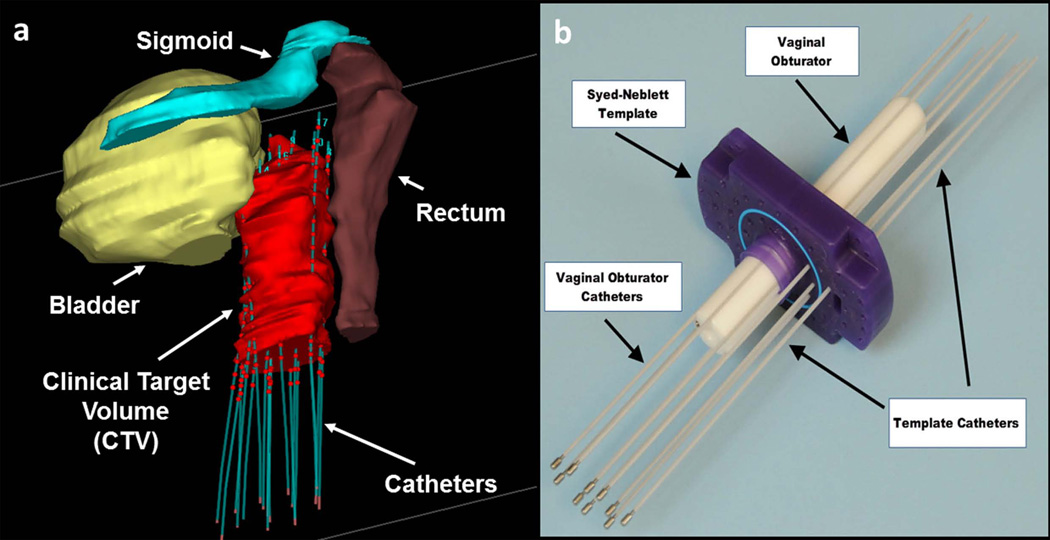
In MRI-guided brachytherapy, multiple (10 – 30) catheters are typically placed into the tumor (Figure 1). Each catheter consists of a hollow tip-sealed plastic tube into which radioactive sources are later temporarily loaded, and a metallic needle (“stylet”) constructed from tungsten alloy to provide the mechanical strength needed to drive the catheter to its desired position. As a result, reliable tracking of a metallic device is crucial to the success of interventional brachytherapy procedures. Currently, MRI-guided brachytherapy is conducted by passively visualizing the magnetic susceptibility image artifact created by the metallic stylet (5). Metal itself does not generate MR signals and the presence of metal can result in severe distortion to the static magnetic field (B0) around it because of the large susceptibility differences with surrounding tissues. The signal voids created by the metal in MR images are used as a negative contrast to identify the device, but the accurate location and size of the device is difficult to determine because the susceptibility artifact on MR images depends on the shape and material properties, the device’s orientation relative to B0, and pulse sequence parameters(6). High-resolution image-based passive tracking methods are typically time-consuming (0.5-2 tracking frames per minute) and may also compromise the contrast-to-noise ratio of anatomic images. Furthermore, this approach becomes more difficult in MR-guided brachytherapy, where the individual paths of multiple catheters need to be tracked, since catheters are close to each other (<10 mm apart) or cross paths during insertion. Various positive contrast techniques have been proposed to image paramagnetic metallic objects, but these approaches offer limited benefit over negative contrast methods (7–11).
Figure 1.
Gynecologic interstitial brachytherapy procedure: (a) 3D model showing organs at risk surrounding the clinical target volume (CTV). Catheters are introduced to regions around and within the tumor. The plastic catheters are filled with rigid metallic stylets during insertion, but thereafter filled with radioactive sources, with the dwelling points during radiation delivery shown as red spheres. Care must be taken not to puncture the bowel, rectum or bladder dung catheter insertion. (b) Photograph of typical equipment used in an MRI-guided procedure. A template (purple), which is a plastic plate with numerous holes, is sutured onto the patient’s skin. A plastic central obturator (white) is then inserted into the vagina to anchor the assembly in place. Multiple catheters are then placed through designated holes in the template and driven towards prescribed locations.
In contrast, active device localization can be achieved via radio-frequency (RF) micro-coils (MR-Tracking) or gradient field measurements, which can generate unambiguous and precise (< 1 mm) 3D location information for multiple micro-coils within a few milliseconds (12–14). However, active tracking is challenging for MR-guided brachytherapy because: (a) the metallic stylet within the catheter leads to B0 and RF (B1) magnetic field inhomogeneities, which are exacerbated by the close proximity of 10-20 needles; (b) RF currents induced in the surface of metallic stylet can distort imaging and cause heating.
In this work, a novel active MR tracking system for brachytherapy was constructed to enable rapid and accurate tracking of the position and orientation of a metallic device by addressing the B0 and B1 challenges. The tracking method utilizes flexible printed circuit (FPC) RF micro-coils mounted on the distal shaft of the metallic stylet. A dedicated pulse sequence with online reconstruction and visualization was developed. This tracking system was tested in phantoms, animals and in three gynecologic cancer patients.
Methods
Construction of the prototype active stylet
In order to convert a commercially-available brachytherapy metallic stylet (Nucletron, Elekta, Stockholm, Sweden), with a length of 300 mm and a diameter of 1.6 mm, into an active MR tracking device, an RF coil design is required to provide a B1− field which extends outside the region of the strong B0 inhomogeneity around the surface of the stylet. This region typically extends 2-3 mm from the surface in a 3T MR scanner (6). The coil design was optimized by electromagnetic (EM) modeling of the receive sensitivity (B1−) of planar coil configurations ranging from 4 mm to 8 mm in length, placed on the metallic needle surface. Similar modeling were also carried out with identical coil geometries placed on an insulating stylet surface in order to understand the lobe-pattern differences created by the two substrates. The EM simulation was carried out at 123.183 MHz (the 3T Larmor frequency) using a finite element method (HFSS 15.0, ANSYS, Canonsburg, PA). The simulation setup contained a tungsten stylet positioned parallel to B0 with the three attached tracking coil immersed at the isocenter of a cylindrical phantom (300 mm high, 200 mm diameter, conductivity: 0.7 S/m, dielectric constant: 78.53). Coil excitation was performed with a 1-W continuous wave signal at 123.183MHz. Sensitivity profiles were calculated for axial and sagittal slices in the center of the tracking coil (15).
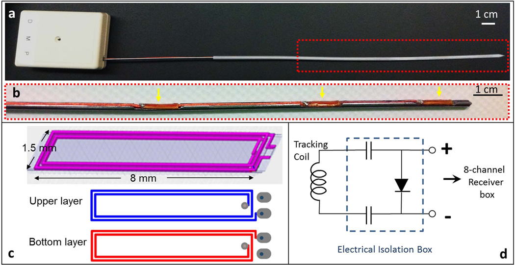
After determining the optimal coil geometry, a prototype micro-coil, consisting of four rectangular conductive loops, was constructed using a double-layered FPC sheet (Figure 2). Three slots (0.7 mm deep, 10 mm long) were machined into the surface of the conventional stylet using a diamond-tipped compression router bit driven by the milling machine, with centers at 10, 30, and 50 mm from the tip, in order to mount three micro-coils (Figure 2b). A shallow groove (200 µm wide and 300 µm deep) was also machined along the entire shaft to conduct the RF cables by using a rotating thin diamond cut-off cutter. Three micro-coaxial cables (Tyco Electronics, outer diameter: 0.2 mm) were passed within the groove along the stylet shaft, with each cable soldered at the distal end to the printed circuit. At the proximal end of the stylet the micro-coils were connected to the MR system via a dedicated eight-channel receiver.
Figure 2.
(a) Photograph of an actively-tracking interstitial brachytherapy catheter, composed of an active metallic stylet, enclosed by a plastic cylindrical cover. The stylet fits into the conventional cover since it has the same external dimensions as a conventional stylet. The white box at the proximal end contains SMB adaptors to connect the three micro-coaxial cables to the receiver box. (b) Enlargement (red dash box in the upper panel) of the distal portion of the active stylet. Three flexible printed circuit (FPC) tracking coils (yellow arrows) were mounted onto the three slots on the surface. (c) Design pattern used in construct of FPC coil. Each coil was built on a double-layered flexible printed circuit sheet, consisting of four rectangular conductive loops. (d) Circuit diagram for each receiver channel in the electrical isolation box (dashed line), which is placed between each micro-coil on the stylet and a single channel in the 8-channel MRI receiver box. The two 0.1 µF capacitors limit leakage currents to less than 10 µA and the pin diode provides the active decoupling signal expected by the receiver.
An RF-shielded electrical isolation box was placed between each active stylet and the receiver to provide electrical current isolation and limit 60Hz leakage currents to less than 10 µA for each channel. The isolation circuit also provided high voltage breakdown protection >1kV, and decoupled the micro-coils during RF transmission (Figure 2d).
The dedicated receiver has a conventional Siemens coil plug and its coil file allowed combination of the MR tracking coils with several imaging coils (the Siemens body phased-array coil and spine coil, as well as the Invivo 32-channel cardiac array), allowing MR-tracking to be performed concurrently with high-resolution imaging.
MR-Tracking Software
All MR tracking and imaging were performed in a 3T MR system (VISIUS iMRI, IMRIS, Winnipeg, Manitoba, Canada). The MR-tracking sequence acquired MR signals from the micro-coils during the application of magnetic field gradients along x, y and z directions. Both zero-phase-reference and Hadamard multiplexing methods were implemented to correct for B0 inhomogeneities (12). Phase-field dithering (PFD) (16) was integrated into the MR Tracking sequence to suppress the B0 and B1 field disturbance caused by the metallic stylets by adding dephasing gradients (gradient moment: 2 mT/m•ms) along assigned directions orthogonal to the readout direction. Signal peak positions were detected using a centroid algorithm, with a predefined frequency window width centered at the position with maximal profile signal intensity (17). When using N > 1 PFD directions, the signals from all N acquisitions were combined using a maximum intensity projection in order to extract the positional information. The sequence can achieve tracking with up to 0.6 × 0.6 × 0.6 mm3 resolution at 40 frames per sec (fps) (N = 1) using a minimum echo time (TE) of 1.89 ms.
The tracking module continuously acquires data when operating in a tracking-only mode, which is used to follow the catheter at the maximal speed. It can also be used in concert with intra-procedural MR imaging, in which MR-tracking is interleaved with an imaging sequence, allowing rapid image acquisition centered on the instantaneous catheter-tip location.
Visualization of Active Stylet
The orientation of the active stylet was determined using the tracked positions of the two distal micro-coils. The position of the stylet tip was extrapolated a known distance (5 mm) beyond the most distal coil using the stylet’s calculated tip orientation. All the tracking information was transferred to an external workstation using the OpenIGTLink protocol (18) in real-time for display. 3D Slicer (www.slicer.org)(19) was used to visualize the individual coil positions as well as the stylet tip position and the shaft orientation. The tracking information was simultaneously or selectively displayed by graphic overlay on previously acquired high-resolution MR images. It is clear that this approach does not account for dynamic changes in the imaged volume, unless this roadmap is updated frequently. The Volume-Reslice-Driver module of 3D Slicer was applied in order to update slices displayed in the three orthogonal views in accordance with the catheter’s instantaneous position. Simultaneous visualization of multiple needles was also possible on this platform.
The 3D Slicer interface was displayed on a monitor inside the MR room allowing observation of catheter motion during catheter manipulation.
Heating Test
The active stylet, without the plastic enclosure, was embedded into a cylindrical plastic bottle filled with a liter of tissue-mimicking gel (2% agar, 0.9% NaCl). The bottle was placed into a Siemens elliptical cross-section loading phantom of human torso dimensions in order to reproduce human 3T B1 profiles. The temperature was measured with a fiber-optic thermometer (m3300; Luxtron, Santa Clara, CA) at a sampling rate of 1 Hz. Three temperature probes were attached to three locations along the stylet shaft with adhesive tape and fixed within the gel: the first one was at the tip of the catheter, the second at the central (second) micro-coil, and the third on the proximal side of the third micro-coil.
A steady state free precession (SSFP) sequence was used: TR/TE = 4.2 ms/1.2 ms; flip angle α = 75°; 5-mm slice; matrix: 128× 128; field of view [FOV] = 200 × 200 mm2, with a whole-body specific absorption rate (SAR) of 3.3 W/kg. The measurement was repeated using a turbo spin echo (TSE) sequence (TR/TE = 184 ms/4.2 ms; α = 129°; 3-mm slice; matrix = 288 × 384; FOV = 220 × 220 mm2, echo train length [ETL] = 21), providing a whole-body SAR of 3.3 W/kg. Both sequences were applied for a period of 15 minutes. To investigate the effects of position within the body coil, temperature measurements were performed at off-center locations (x and y positions): 0 cm, ±5cm, ±10 cm, and ±16 cm from the center of the magnet. These measurements are in line with previously detailed methods (20, 21).
Phantom Study
Static positional tracking was performed with the active stylet, placed in a plastic closure, inserted into the same agar phantom described above, in order to calibrate the distance offset. This is required for accurate determination of spatial location, since in this setup MR signal was obtained distance away from the metallic stylet surface, and the distance offset is equal to the distance from the strongest tracking signal received by the coil to the central axis of the stylet. It was calibrated by calculating half of the distance between two positions measured with the tracking coil facing two opposite directions (i.e., by rotating the stylet by 180° around its axis). This measurement was performed with the phantom placed at six different locations. At each location, the measurement was repeated for 1000 times with stylet oriented either parallel to the B0 field or 45° relative to the B0 field in the x-z plane.
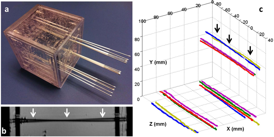
To validate dynamic tracking, a plastic cubic container (150 × 150 × 150 mm3) with one open side was used to build a second gel phantom. Two identical plastic templates with 5 mm grid of holes were fixed at the open side of the container and its opposite side respectively for catheter alignment and image registration. Fifteen catheters with conventional stylets were inserted through one hole from each of the template and gel was then allowed to solidify in the container (Figure 6a).
Figure 6.
(a) Gel phantom with fifteen catheters inserted. All the catheters initially contained conventional stylets within them. A set of five stylets were placed into each of the three corners of the cubic phantom. In each set, three stylets were almost parallel to each other, while two crossed each other. (b) A high-resolution sagittal MR image of the phantom. The two black lines (white arrows) show two catheters that cross each other, which is difficult to identify because it can also represent two touching bent catheters. (c) Fifteen stylet trajectories acquired by capturing the tracked tip position continuously during active stylet pull-out. In all cases, the active tracking system generated stable tracking signal profiles and resolved the trajectories well. Note that two stylets at each of the three corners crossed each other, with the two at the upper corner (black arrows) also shown in b.
The phantom with catheters was placed into the MR scanner with the open side facing the foot direction. High-resolution MR images were acquired using a 3D inversion-recovery gradient echo (MP-RAGE) sequence (TR/TE/TI = 1200 ms /1.55 ms/ 900 ms; flip angle α = 75°; 5-mm slice, matrix = 312× 384; FOV = 162 × 199 mm2).
The active stylet was used to replace, in turn, each of the fifteen conventional stylets in turn during MR tracking while all of the plastic hollow enclosures remained at their original locations. Each individual coil position was continuously recorded during active stylet insertion and pull-out to extract the full catheter trajectory. The trajectories of all the catheters were also reconstructed based on the susceptibility artifacts seen in the MR images using the Oncentra Brachytherapy planning system (Nucletron, Elekta, Stockholm, Sweden) and compared to the tracking data.
Animal Study
Active tracking was tested in one cleaned (i.e., with the central organs removed) chicken carcass. High-resolution 3D imaging of the whole chicken was performed with an MP-RAGE sequence using the 32-channel cardiac coil (Invivo Corporation, Gainesville, FL) (resolution: 0.7 × 0.7 × 0.8 mm3). The imaging data set was loaded into 3D Slicer. The active stylet was then manually used to puncture the chicken skin and advanced within the chicken with the tracking sequence running continuously throughout the navigation process (resolution: 0.6 × 0.6× 0.6 mm3, 16 fps, PFD N=3). The position of the distal tip and its orientation were visualized using 3D Slicer in real-time.
During navigation, 3D Slicer produced instantaneous slices at the tip of the stylet along the axial, sagittal and coronal directions, based on reformatted images from the 3D imaging data set. A first-order temporal low-pass (5Hz) filter was applied to remove rapid changes in catheter location, in order to provide a smoother temporal variation in location.
Patient Study
With IRB approval, active MR-tracking was conducted for catheter placement in three female patients with gynecologic cancer. A T2-weighted axial data set, covering the entire anatomical region from the bladder down to the vagina, was acquired using a TSE sequence (TR/TE = 3000 ms/ 104 ms; α = 120°; 5-mm slice; matrix = 205 × 320; FOV = 224 × 280 mm, ETL = 27). This set was used as the background (the “roadmap”) on which the position of the actively-tracked stylets was displayed.
In the course of the procedures, 12-30 catheters were first placed into the patients using conventional stylets. One conventional stylet was then pulled out and replaced by the active stylet. The TSE data set was reacquired with the micro-coils now used as three additional imaging coils, together with the Siemens phased array coils, so that the three could be observed at rest as bright spots in the images.
MR tracking was then performed continuously during the insertion of the active stylet (resolution: 1.2 × 1.2 × 1.2 mm3, α = 5°, PFD N=3, 16 fps). The calculated catheter tip position and orientation were displayed in real time as overlays on the background of the pre-acquired TSE data set on 3D Slicer. After the placement of the catheters, the full needle trajectories were reconstructed by continuously tracking the position of the stylet’s tip during a pull-out. In this preliminary study, IRB approval did not include the use of the active-tracking data to guide the procedure.
Results
Simulation and Actual Performance of the Micro-coils on Metal
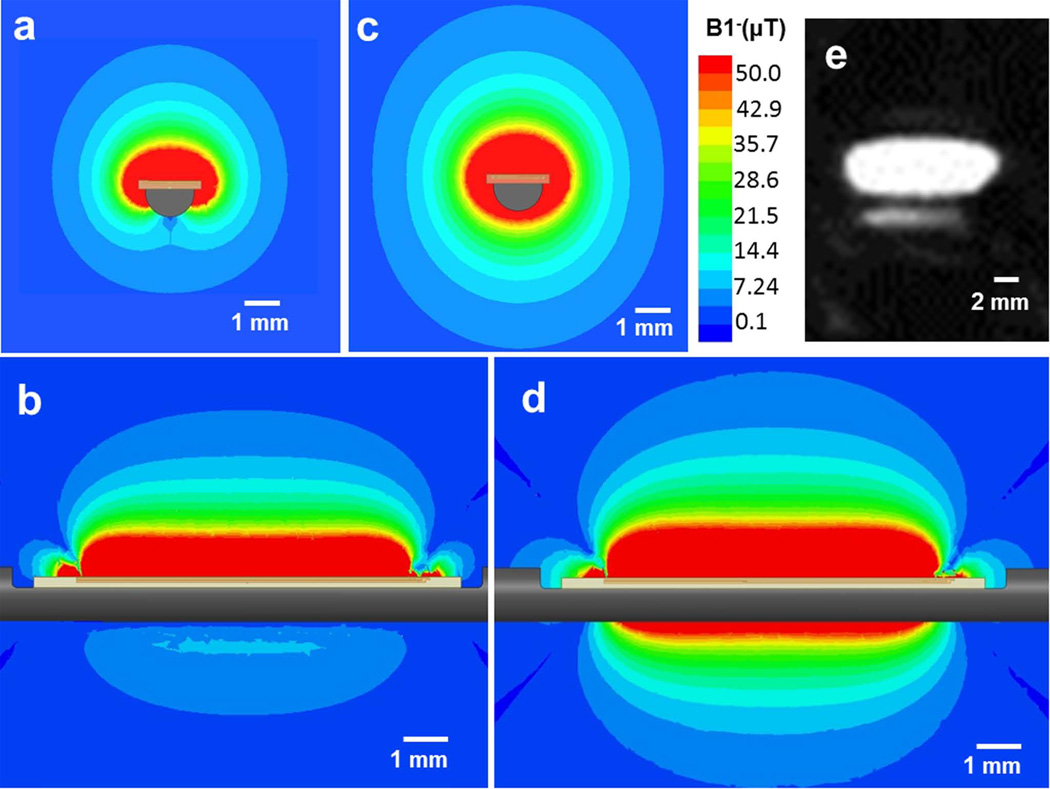
The B1− field (Figure 3a and 3b) of an 8-mm length planar micro-coil lies perpendicular to the metallic stylet surface, with its profile extending approximately 5 mm from the surface, which is beyond the area (~ 2 mm from surface (6)) where the susceptibility-induced B0 gradient is far greater than the strength of the frequency encoding gradient applied by the tracking sequence. This field profile is still adequately spatially localized (3 mm × 8 mm × 2 mm), which is essential for accurate tracking. Actual measurement of the RF lobe pattern (Figure 3e) using a TSE sequence disclosed that the pattern was very similar to that simulated.
Figure 3.
(a) Axial view (cross-section of the stylet) and (b) sagittal view (along and perpendicular to the shaft) of the B1− EM field simulation with an 8-mm-long micro-coil attached to a metallic stylet. (c) Axial view and (d) sagittal view the B1− EM field simulation with the same micro-coil attached to an insulating stylet. Note that the lobe pattern obtained with the metallic substrate is far smaller than that with the insulating substrate. (e) A high-resolution MR image of a tracking coil mounted on the metallic stylet, acquired with a 3D Turbo Spin Echo sequence. The imaging slice was oriented in the sagittal plane along the active stylet shaft. It demonstrates that strong signal is obtained ~5 mm away from the needle surface.
The B1− field of the same micro-coil on an insulating stylet is shown in Figure 3c and 3d for comparison. It is apparent that the RF lobe pattern on the metallic surface is significantly reduced as compared to that obtained on insulators. For this reason, metallic surfaces require the placement of larger dimension micro-coils (or alternatively use of RF lobe patterns that project further away from the surface, such as bent “butterfly” coils) in order to provide lobe patterns that allow for accurate positional localization, when using conventional millisecond-scale echo times (i.e., non-ultrashort TEs).
In addition, the EM simulation provided an estimate of the RF eddy currents created in the metal surface below the micro-coils. We found that the eddy currents were highly localized within the metallic skin depth lying just below the micro-coils. These currents were of small initial amplitude, and decayed quickly over time in the highly conductive metal.
Heating Test
The high SAR scanning in all of the heating experiments resulted in a very small amount of heating. The greatest temperature increase recorded (0.6 °C) over a 15 minute scan occurred when the phantom was at the most off-center position (+16 cm along×or y).
Phantom Study
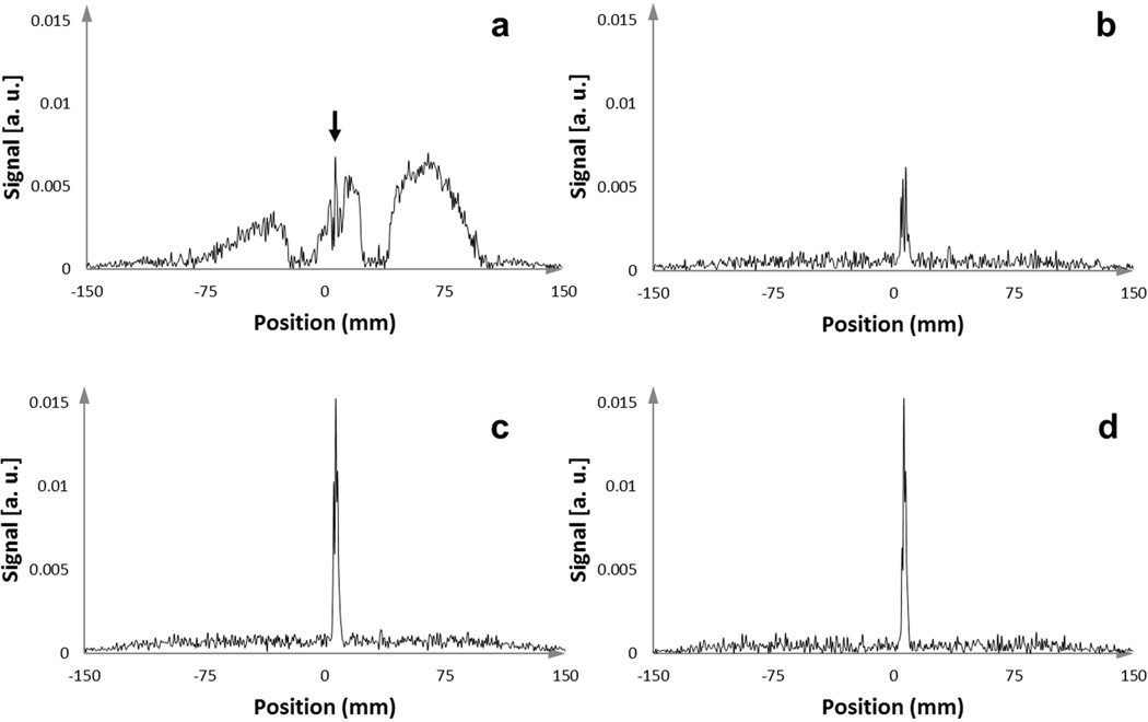
Use of even a single dephasing gradient (PFD N=1) provided a sharp peak in the signal intensity profile from the active stylet by eliminating the broad signal arising from coupling to the neighboring stylets (Figure 4). The signal intensity varied as the dephasing gradient was applied in the different orthogonal directions. By combining these three signals, the chances of obtaining a robust tracking signal was greatly improved, so PFD was subsequently used in all animal and human scans.
Figure 4.
One-dimensional MR-tracking signal-intensity profiles acquired with an active stylet filled catheter after insertion into the gel phantom, which contained 14 other conventional stylets. (a) Signal intensity profile from acquisition without applying an orthogonal dephasing gradient. In this case, the broad signal from the coupled surrounding stylets overwhelmed the peak from the micro-coil, resulting in the in-ability to obtain the true micro-coil location (the narrow peak highlighted with the black arrow). (b,c) Signal intensity profiles from acquisition with orthogonal PFD gradients applied in two different directions. Some PFD directions were superior in preserving the signal from the micro-coil while suppressing the broad surrounding signals. (d) Tracking signal, achieved by applying a maximum intensity projection to the intensity profiles generated from three different orthogonal dephasing gradients, provided a very high SNR to determine the micro-coil location.
In the static tracking experiment, the distance offset was 1.0 ± 0.1 mm when the stylet was along the B0 field and 1.5 mm ± 0.1 mm when it was 45° relative to the B0 field. Since the difference between the offsets measured with different orientations is comparable to the resolution limit and measurement error of the system, we incorporated a 1-mm offset into the reconstruction for the subsequent animal and human studies. Note that this distance offset was always along the direction perpendicular to the stylet surface so in the calculation of each tracking cycle it was decomposed into three offsets for x, y and z coordinates by using the stylet’s orientation acquired from the previous tracking cycle, assuming that the stylet’s orientation was not changed much after one tracking TR.
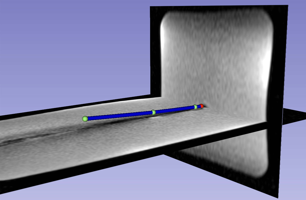
Figure 5 shows a visualization of a slightly bent distal shaft of a catheter, based on the measured positions from three tracking coils and the extrapolated tip positions. Electromagnetic tracking methods used outside the field of MRI, as well as existing active-tracking methods for metallic devices used in MRI, which consist of placement of tracking sensors on “hand-holders” attached to the proximal end of these devices, cannot provide information on the bending of devices. Since the bending of devices is common during the insertion of the devices into human tissue, visualization of the distal shaft curvature may provide important clinical information during navigation.
Figure 5.
The distal shaft of a slightly bent brachytherapy catheter, which included an active stylet, inside a gel phantom, as visualized on the 3D Slicer workstation. Three coil positions (green spheres) and the extrapolated tip position (red sphere) are shown. The catheters distal shaft (blue cylinder) was reconstructed using a spline fit to the four positions and overlaid on a pre-acquired high-resolution 3D MR image data set, demonstrating the capability of the tracking system to show curvature of the catheter.
In the dynamic tracking experiment, the tracking trajectories of the catheters (Figure 6) were compared with the signal voids observed in the high-resolution MR images. The distances between the tracked points to the center of the signal voids on the axial MR images were all within 0.5 mm, which implies a location precision of ± 0.5 mm.
Animal study
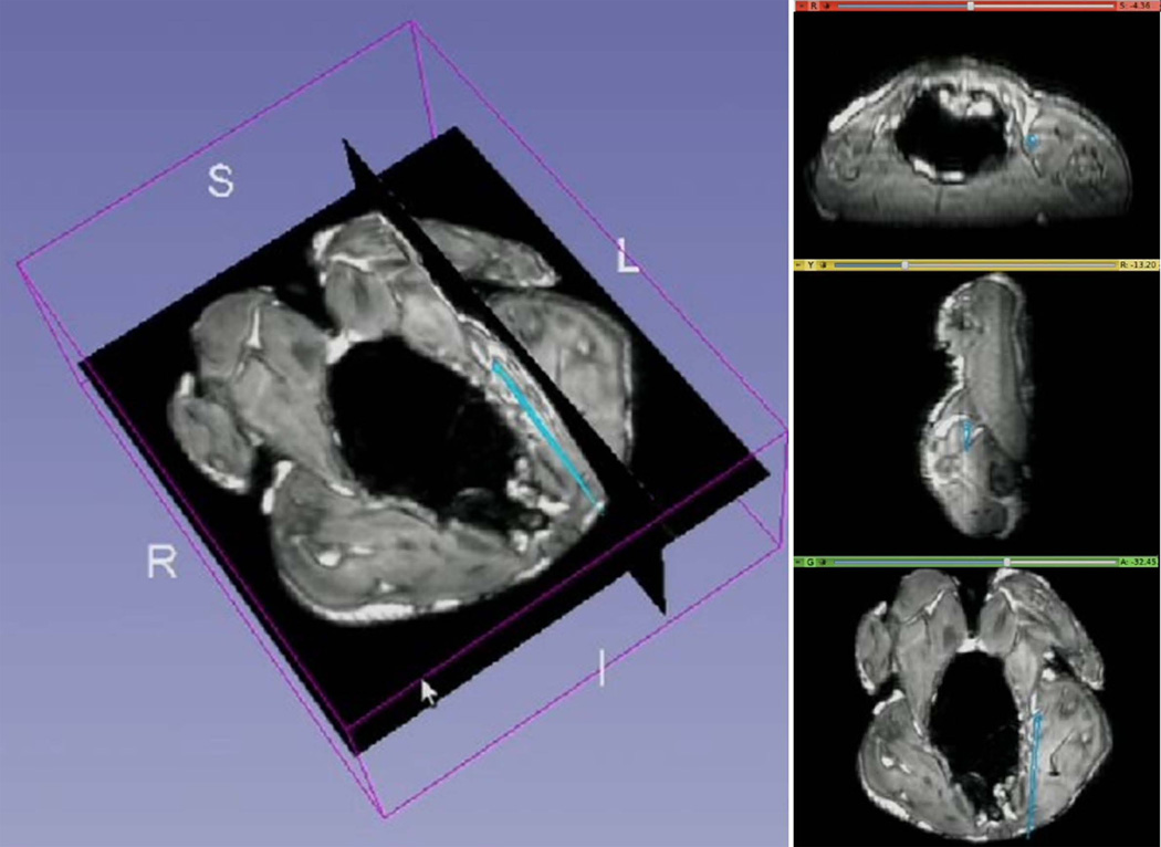
Throughout the animal experiment, the tracking SNR was 20 – 250 (mean 160). Figure 7 shows a screenshot of the 3D Slicer visualization interface during MR-guided catheter navigation within the chicken. The instantaneous position and orientation of the catheter was displayed as a colored vector overlaid on the pre-acquired images. The temporal low pass filter allowed for easier visualization during navigation by removing unwanted “jitter” of the catheter location.
Figure 7.
Navigation of a catheter including an active stylet in a cleaned chicken, as visualized on the 3D Slicer workstation. The catheters tip’s position and orientation (cyan colored straight lines) were overlaid on pre-acquired high-resolution 3D MR images. Images on right are (top to bottom) axial, sagittal and coronal slices created in real-time at the position of the catheter tip.
Patient Study
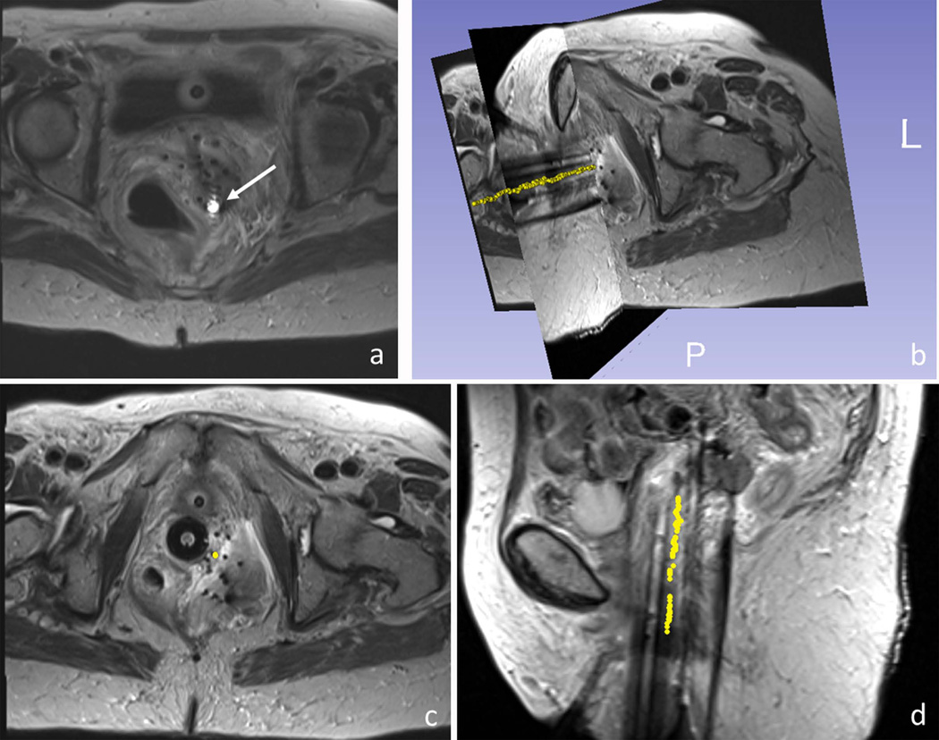
In the patient studies, the micro-coils on the active stylet provided robust localized signals inside the pelvis, which was shown as bright spots in the TSE image, on the background of surrounding anatomy (Figure 8a). The SNR of tracking acquired in the human was 20 – 220 (mean 150) when the stylets were at rest and 18 – 130 (mean 100) when moving. The calculated catheter-tip position and orientation was displayed on the background of the pre-acquired data set. The full trajectory of one catheter reconstructed from the tracking data is shown in Figure 8b-d. This shows the high consistency between points along the reconstructed needle trajectories and the signal voids observed in the TSE images, which are commonly used to passively track these metallic stylets.
Figure 8.
MR-guided catheter placement utilizing the active stylet in a gynecologic cancer patient. (a) Active micro-coil (white arrow) was detected on images using an array that included the tracking coils and the MRI’s surface coils. 3D rendering (b) and axial and sagittal views (c,d) of a single active stylet trajectory (yellow dots), overlaid on 3D turbo spin echo images of the patient’s pelvis. The trajectory (yellow points) was reconstructed by consecutively tracking the positions of the catheter tip during stylet pull-out.
Discussion
An actively-tracked stylet was designed and constructed for radiation therapy. By moving from passive to active tracking, we increased the resolution of catheter localization from 3 mm to 0.6 mm (5). Better catheter placement will allow physicians to perform improved radiation treatment by avoiding excessive doses to the surrounding tissues, as well as potentially placing fewer catheters into the patient. This modified procedure may result in faster patient recovery, as well as a reduced risk of accidental perforation of neighboring tissues, such as the bowel, the bladder, or the rectum.
Compared to passive high-resolution catheter tracking with 3D SSFP imaging (5), which requires ~2 minutes per slab, active tracking improved the tracking speed from 0.1 Hz to 16-40 Hz, which allows for faster procedures, as well as providing real-time feedback of location during the insertion, which can better guide catheter placement.
By making the metallic stylet active, the dimensions and the mechanical properties of the stylet were preserved. It is very difficult to preserve these properties and maintain the dimensions when replacing sections of the metallic stylet with other materials, such as plastics or ceramics. The ability to accurately track both the tip and the shaft of metallic stylets suggests that it may be possible to convert other interventional devices, such as guide-wires, sheathes, cannulas, and trocars, into actively tracked devices, while preserving their specialized mechanical properties. Although it has been reported that an interconnected string of solenoid RF coils can be used to visualize points along the shaft of a metallic needle, based upon the RF coils’ hyper-intense appearance during imaging (22), this (“semi-active”) method for device tracking typically requires much longer acquisition times, and it does not provide the exact locations of the points. The only method currently available to track the shaft of metallic devices during interventional procedures conducted inside (or outside) MRI is optical-fiber Bragg grating (FBG) (23). Since brittle glass fibers are used, the amount of device bending allowed is greatly restricted, whereas mechanical testing performed on our stylets demonstrated the ability to bend them by more than 180 degrees without damaging the stylet.
An additional advantage of active tracking may be within reach if MRI data can be used to modulate the dose delivered to different sections of a tumor during brachytherapy. There is increasing evidence that diffusion-weighted imaging or dynamic contrast enhanced imaging can provide information on regions of the tumor which remains after external beam radiation treatment (24, 25). If this information was acquired during the radiation treatment cycle, dose modulation could be performed to reduce the chances for tumor recurrence. For example, a larger density of catheters could be placed into a region of the tumor which is more resistant to therapy, such as a low-oxygenated (hypoxic) region.
A major prerequisite for successful active tracking on metallic surface was our RF coil design which, as compared to a conventional solenoid micro-coil, has a B1- field perpendicular to the surface of the metal. This enabled the sensitivity profile to extend beyond the inhomogeneous B0 region around the metallic surface. For the tracking pulse sequence, an asymmetric refocusing echo was used, which reduced the short T2* effect arising from the susceptibility differences by shortening the echo time, and also suppressed the broad features from the inductive coupling to neighboring stylets. Use of phase-field dithering is essential for this application. The effect of B1 inhomogeneities and the inductive RF coupling from the surrounding stylets were greatly reduced with phase-field dithering. Although the tracking speed was somewhat reduced, it generated a more reliable tracking signal by combining the signals acquired with dephasing gradients applied in different directions. We used three directions in our routine protocol, from which a combination of signals was found to have sufficiently enough SNR to generate positional information with reasonably fast tracking speed (16 Hz).
Despite the use of metallic materials, the RF heating observed was well below FDA limits. This is a result of the fact that the stylets were only 30 cm long, forming less than a quarter wavelength at 123 MHz (~ 60 cm in the metal), so standing waves were not formed along the metallic stylet. We believe that in the current design, where the micro-coaxial cables are embedded within the metal, the directly induced B1 field of the coaxial cables will be negligible. As a result, in order to make longer metallic devices active, such as 120 cm long guidewires, a method would need to be developed to prevent (or dampen) RF standing waves forming on the surface of (i.e. at skin depths within) the metal.
In this study, our coil design was limited by the machining of a commercially available stylet. Ideally, the micro-coils could be placed symmetrically (i.e., as an “onion ring”) around the shaft of the stylet, which would have prevented the need to perform offset calculations. Our current design produced an offset of 1 mm between the detected position and the real position of the stylet, along the direction perpendicular to the stylet shaft. This shift was quantified by the phantom measurements and was taken into account in all subsequent animal and human experiments. Because the offset depends on many factors, e.g. the stylet orientation and surroundings, which we have no prior knowledge of during the real-time tracking, using a universal offset will definitely cause some error to the measurement although it is fairly small and comparable to our resolution limit.
In future work, we plan to use MR-tracking in concert with intra-procedural MR imaging, in which tracking will be temporally interleaved with real-time imaging, allowing rapid image acquisition centered on instantaneous catheter-tip location. This will assist in determining the proximity of targets to the current needle tip position, and can be used to monitor dynamic changes induced by the needle tip, such as tissue displacement or strong tissue resistance which can cause catheter deflection. Such changes in catheter path are important for clinicians to know, especially when the catheter has been substantially advanced and “fine tuning” of the tip is required. Another potential application will be to use the tracking information to perform motion correction on high-resolution images of the pelvis.
Conclusion
For the first time, an actively-tracked metallic catheter with dedicated MR-tracking software was successfully applied in clinical cases. This tracking platform will facilitate accurate and time-efficient catheter placement, and will enable identification of preferential paths to target locations, and has the potential to reduce the radiation dose to critical organs. This approach can be extended to other interventions requiring metallic devices.
Acknowledgments
We gratefully acknowledge support from the American Heart Association 10SDG2610139, NIH 1R21CA158987-01A1, U41-RR019703, R21 CA 167800, as well as a BWH Department of Radiation Oncology post-doctoral fellowship support. We also gratefully acknowledge IMRIS Inc., for constructing and interfacing the 8-channel coil interface.
References
- 1.Cancer facts and figures 2013. 250 Williams Street, NW, Atlanta, GA A 30303-1002: Corporate Center: American Cancer Society Inc.; [Google Scholar]
- 2.Han K, Milosevic M, Fyles A, Pintilie M, Viswanathan AN. Trends in the utilization of brachytherapy in cervical cancer in the United States. International journal of radiation oncology, biology, physics. 2013;87(1):111–119. doi: 10.1016/j.ijrobp.2013.05.033. [DOI] [PubMed] [Google Scholar]
- 3.Viswanathan AN, Cormack R, Holloway CL, Tanaka C, O'Farrell D, Devlin PM, Tempany C. Magnetic resonance-guided interstitial therapy for vaginal recurrence of endometrial cancer. International journal of radiation oncology, biology, physics. 2006;66(1):91–99. doi: 10.1016/j.ijrobp.2006.04.037. [DOI] [PubMed] [Google Scholar]
- 4.Viswanathan AN, Szymonifka J, Tempany-Afdhal CM, O'Farrell DA, Cormack RA. A prospective trial of real-time magnetic resonance-guided catheter placement in interstitial gynecologic brachytherapy. Brachytherapy. 2013;12(3):240–247. doi: 10.1016/j.brachy.2012.08.006. [DOI] [PubMed] [Google Scholar]
- 5.Kapur T, Egger J, Damato A, Schmidt EJ, Viswanathan AN. 3-T MR-guided brachytherapy for gynecologic malignancies. Magnetic resonance imaging. 2012;30(9):1279–1290. doi: 10.1016/j.mri.2012.06.003. [DOI] [PMC free article] [PubMed] [Google Scholar]
- 6.Müller-Bierl B, Graf H, Lauer U, Steidle G, Schick F. Numerical modeling of needle tip artifacts in MR gradient echo imaging. Medical physics. 2004;31(3):579–587. doi: 10.1118/1.1640971. [DOI] [PubMed] [Google Scholar]
- 7.Seevinck PR, de Leeuw H, Bos C, Bakker CJ. Highly localized positive contrast of small paramagnetic objects using 3D center-out radial sampling with off-resonance reception. Magnetic resonance in medicine. 2011;65(1):146–156. doi: 10.1002/mrm.22594. [DOI] [PubMed] [Google Scholar]
- 8.Dahnke H, Liu W, Herzka D, Frank JA, Schaeffter T. Susceptibility gradient mapping (SGM): A new postprocessing method for positive contrast generation applied to superparamagnetic iron oxide particle (SPIO)-labeled cells. Magnetic Resonance in Medicine. 2008;60(3):595–603. doi: 10.1002/mrm.21478. [DOI] [PMC free article] [PubMed] [Google Scholar]
- 9.Cunningham CH, Arai T, Yang PC, McConnell MV, Pauly JM, Conolly SM. Positive contrast magnetic resonance imaging of cells labeled with magnetic nanoparticles. Magnetic Resonance in Medicine. 2005;53(5):999–1005. doi: 10.1002/mrm.20477. [DOI] [PubMed] [Google Scholar]
- 10.Mani V, Briley-Saebo KC, Itskovich VV, Samber DD, Fayad ZA. Gradient echo acquisition for superparamagnetic particles with positive contrast (GRASP): sequence characterization in membrane and glass superparamagnetic iron oxide phantoms at 1.5 T and 3T. Magnetic resonance in medicine. 2006;55(1):126–135. doi: 10.1002/mrm.20739. [DOI] [PubMed] [Google Scholar]
- 11.Seppenwoolde JH, Viergever MA, Bakker CJ. Passive tracking exploiting local signal conservation: the white marker phenomenon. Magnetic resonance in medicine. 2003;50(4):784–790. doi: 10.1002/mrm.10574. [DOI] [PubMed] [Google Scholar]
- 12.Dumoulin CL, Souza SP, Darrow RD. Real-time position monitoring of invasive devices using magnetic resonance. Magnetic resonance in medicine. 1993;29(3):411–415. doi: 10.1002/mrm.1910290322. [DOI] [PubMed] [Google Scholar]
- 13.Bock M, Umathum R, Sikora J, Brenner S, Aguor E, Semmler W. A Faraday effect position sensor for interventional magnetic resonance imaging. Physics in medicine and biology. 2006;51(4):999. doi: 10.1088/0031-9155/51/4/016. [DOI] [PubMed] [Google Scholar]
- 14.Scheffler K, Korvink J. Navigation with Hall sensor device for interventional MRI. 2004:950. [Google Scholar]
- 15.Collins CM, Smith MB. Calculations of B(1) distribution, SNR, and SAR for a surface coil adjacent to an anatomically-accurate human body model. Magnetic resonance in medicine. 2001;45(4):692–699. doi: 10.1002/mrm.1092. [DOI] [PubMed] [Google Scholar]
- 16.Dumoulin CL, Mallozzi RP, Darrow RD, Schmidt EJ. Phase-field dithering for active catheter tracking. Magnetic resonance in medicine. 2010;63(5):1398–1403. doi: 10.1002/mrm.22297. [DOI] [PubMed] [Google Scholar]
- 17.Dumoulin CL. Method and system for tracking small coils using magnetic resonance. Google Patents. 2004 [Google Scholar]
- 18.Tokuda J, Fischer GS, Papademetris X, Yaniv Z, Ibanez L, Cheng P, Liu H, Blevins J, Arata J, Golby AJ. OpenIGTLink: an open network protocol for image-guided therapy environment. The International Journal of Medical Robotics and Computer Assisted Surgery. 2009;5(4):423–434. doi: 10.1002/rcs.274. [DOI] [PMC free article] [PubMed] [Google Scholar]
- 19.Fedorov A, Beichel R, Kalpathy-Cramer J, Finet J, Fillion-Robin J-C, Pujol S, Bauer C, Jennings D, Fennessy F, Sonka M. 3D Slicer as an image computing platform for the Quantitative Imaging Network. Magnetic resonance imaging. 2012;30(9):1323–1341. doi: 10.1016/j.mri.2012.05.001. [DOI] [PMC free article] [PubMed] [Google Scholar]
- 20.Nitz WR, Oppelt A, Renz W, Manke C, Lenhart M, Link J. On the heating of linear conductive structures as guide wires and catheters in interventional MRI. Journal of magnetic resonance imaging : JMRI. 2001;13(1):105–114. doi: 10.1002/1522-2586(200101)13:1<105::aid-jmri1016>3.0.co;2-0. [DOI] [PubMed] [Google Scholar]
- 21.Yeung CJ, Susil RC, Atalar E. RF safety of wires in interventional MRI: using a safety index. Magnetic resonance in medicine. 2002;47(1):187–193. doi: 10.1002/mrm.10037. [DOI] [PubMed] [Google Scholar]
- 22.Saikus CE, Ratnayaka K, Barbash IM, Colyer JH, Kocaturk O, Faranesh AZ, Lederman RJ. MRI-guided vascular access with an active visualization needle. Journal of Magnetic Resonance Imaging. 2011;34(5):1159–1166. doi: 10.1002/jmri.22715. [DOI] [PMC free article] [PubMed] [Google Scholar]
- 23.Park Y-L, Elayaperumal S, Daniel B, Ryu SC, Shin M, Savall J, Black RJ, Moslehi B, Cutkosky MR. Real-time estimation of 3-D needle shape and deflection for MRI-guided interventions. Mechatronics, IEEE/ASME Transactions on. 2010;15(6):906–915. doi: 10.1109/TMECH.2010.2080360. [DOI] [PMC free article] [PubMed] [Google Scholar]
- 24.Haack S, Pedersen EM, Jespersen SN, Kallehauge JF, Lindegaard JC, Tanderup K. Apparent diffusion coefficients in GEC ESTRO target volumes for image guided adaptive brachytherapy of locally advanced cervical cancer. Acta Oncologica. 2010;49(7):978–983. doi: 10.3109/0284186X.2010.500619. [DOI] [PubMed] [Google Scholar]
- 25.Huang Z, Mayr NA, Lo SS, Grecula JC, Wang JZ, Jia G, Yuh WT. Characterizing at-Risk Voxels by Using Perfusion Magnetic Resonance Imaging for Cervical Cancer during Radiotherapy. Journal of cancer science & therapy. 2012;4(9):254. doi: 10.4172/1948-5956.1000151. [DOI] [PMC free article] [PubMed] [Google Scholar]


