

Abstract
Background: Despite some successful dynamic simulation of self-impact double pendulum (SIDP)-as humanoid robots legs or arms- studies, there is limited information available about the control of one leg locomotion.
Objective: The main goal of this research is to improve the reliability of the mammalians leg locomotion and building more elaborated models close to the natural movements, by modeling the swing leg as a SIDP. This paper also presents the control design for a SIDP by a nonlinear model-based control method. To achieve this goal, the available data of normal human gait will be taken as the desired trajectories of the hip and knee joints.
Method: The model is characterized by the constraint that occurs at the knee joint (the lower joint of the model) in both dynamic modeling and control design. Since the system dynamics is nonlinear, the MIMO Input-Output Feedback Linearization method will be employed for control purposes.
Results: The first constraint in forward impact simulation happens at 0.5 rad where the speed of the upper link is increased to 2.5 rad/sec. and the speed of the lower link is reduced to -5 rad/sec. The subsequent constraints occur rather moderately. In the case of both backward and forward constraints simulation, the backward impact occurs at -0.5 rad and the speeds of the upper and lower links increase to 2.2 and 1.5 rad/sec., respectively.
Conclusion: The designed controller performed suitably well and regulated the system accurately.
Keywords: Leg locomotion, Self-impact joint constraint, Double pendulum, Feedback linearization, Single support phase, Swing leg
Introduction
Biomechanics of rhythmic movements and cycles are -to a large extent- the application of Newtonian mechanics to the physiology and neuromuscular skeletal systems [1]. Of all actions with recurring patterns, walking is the most remarkable one that has reached to an exciting phase of research. As far as study of the actions like walking is helpful to investigate, the functional aspects of human locomotion, details, different stand points, and new angles of the influential factors such as stability, efficiency and above all control of biomechanical simulations should be studied more accurately.
Leg Locomotion
The leg locomotion is one of the most complicated motions of a human body or similarly structured humanoid robots due to its complicated physics [2]. The human walking is characterized by excellent efficiency, stability and neural muscular control [3]. Walking is a complex task with some branches of biomechanical minors that must be successfully performed including body support, forward propulsion, and leg swing. [4, 5]. The basin (pan), thigh and foreleg complex is a versatile complex of joints, muscles, bones and neurons where the Central Nervous System (CNS) determines a gait pattern with an appropriate balance between efficiency and stability [3] of the mentioned complex which forms the neuromuscular control mechanism.
This control mechanism is not limited to foot motion since it is also capable of controlling the arm movement, though it hasn’t been considered as a cyclic motion. The point that most biomechanical control engineers have targeted is to control the human motions with the stability that the CNS performs. For that, a more precise study on each part of the human walking or running could result in better outcome.
SIDP System
Due to importance of biomechanical motions, such as walking, running or arm motion, in improving prosthetics for gait-impaired, helping to correct neural muscular deficiencies, or building better two legged (biped) walking robots [6], they have to be simulated by a more stable model with better efficiency and accuracy. For this purpose, the whole walking motion can be simulated as an inverted pendulum, where one-leg locomotion with a stopper at the lower joint corresponds to a self-impact double pendulum; controlling of which is a benchmark problem in biomedical and control engineering. That’s why perhaps the human beings have the most sophisticated brain and CNS system among all animal kingdoms consisting of some 10 billion neurons and 60 trillion interconnections among them [7]. It is also important to note that the stability and control of the simulated single-leg or single-arm motions, as the most significant body movements, have large consequences on the behavior of the whole body locomotion. Furthermore it has been proved that poor lower extremity neuromuscular control during athletic movements may create potentially injurious alignment and excessive knee joint forces [8]; this emphasizes the importance of advancing researches through these simulations. A few of researchers have considered the dynamic modeling of Self Impact Double Pendulum but there is less information available about the control of one leg locomotion as one part of whole gait cycle despite its leading role in biomedical engineering.
Material and Methods
Modelling of SIDP
The way in which the humanoid systems particularly the gait cycles are modeled is a determining factor since this study has proved that the loading response that occurs as the foot impacts the ground during single leg landing, creates a chain reaction through multiple joint linkages [9-11].
In case of biomechanical modeling, the basin, thigh, knee, and forelegs complex, which consists of bones, tendons, etc., can be simulated as two links; where thigh is considered as the first link that is jointed with basin and knee. Also, the foreleg is assumed as the second link that is connected to thigh by knee. The knee joint (the lower joint) by itself is considered as a patella-femoral joint.
To simply model the SIDP, the upper-link rotation angle from a vertical position is denoted by θ1 and the corresponding rotation angle for the lower-link by θ2. The length of link between basin and knee joints is shown by l1 and l2 does the same for the link which is between knee and ankle. Also, an actuator is attached to each joint in addition to a torsional spring-damper system that has been installed on the lower joint to model and simulate the constraint, see figure 1. Furthermore, friction and other dissipating forces have been assumed negligible.
Figure 1.
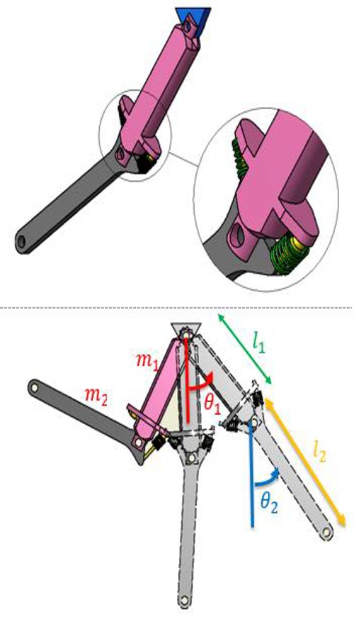
The schematic and parameters of the model.
Modelling of the Constraint in SIDP
The constraint in SIPD has been divided in two categories as follows:
Forward constraint
Backward constraint
The forward constraint occurs when θ2> θ1. Considering the Unit-Step Function that acts and also applies force whenever θ2> θ1, the system accelerates toward the reverse direction. (figure 2)
Figure 2.
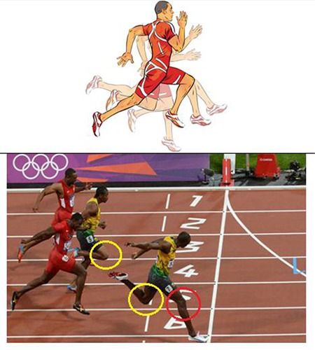
Schematic and real joint self-impact knee joint, between thigh and shank in front and rear, when running fast.
There another constraint can appear in the condition that θ2 is negative and θ1-θ2>(120°=2π/3 rad), and is called “Backward constraint”. To simulate this constraint, the unit-step function has been employed again. In fact, the force and damper spring will be applied to the system when the stopper takes action. The moments implied to the system exist out of the control command; so, the controller does not perceive the constraint and tries to turn the new situation of the system to the desired one. (figure 2)
Mathematical Modelling of SIDP
Detailed discussion for deriving the Lagrangian equations of the dynamical system is given in [12]; moreover the state space equations will be obtained in the following section.
State Space Representation
The state-space form of dynamical equations of a swing leg modelled as a constrained double pendulum may be developed in the following set of equations:
in which, the state variables are:
x1=θ1: Angular displacement of the upper link
x2=θ̇1: Angular velocity of the upper link
x3=θ2: Angular displacement of the lower link
x4=θ̇2: Angular velocity of the lower link
and,
Where, the moments that simulate forward and backward constraints and contain approximated step function are:
and r is the order of accuracy of the approximated unit step function.
Also, the output equations are:
and the input control variables are:
u1=τ1: The external (motor) torque applied to the upper joint
u2=τ2: The external (motor) torque applied to the lower joint
The above model of a swing leg as a constrained double pendulum can be written, for further study, in a compact affine form as:
Input-Output Feedback Linearization
By input-output linearization it is meant the generation of a linear differential relation between the output “y” and a new input”v” [13 , 14]. Given the nonlinear system in (7) and (8), input-output linearization of the system can be obtained by differentiating the output yi until all the inputs appear. Assume that ri , the partial relative degrees, is the smallest integer such that at least one of the inputs appears in , yrii , then
with
for at least one output. Performing the above procedure for each output, yi, yields:
where, Lfh=∇h.f
h:Rn→R a smooth scalar function
f:Rn→Rn a smooth vector field on Rn
and the non-singular m×m matrix E(x) is systematically obtained during taking the derivatives of the outputs.
If, as assumed above, the partial relative degrees (relative degree of a nonlinear system is equal to required number of differentiation of the output of a system to generate an explicit relationship between the output y and input u) ri are all well-defined, then Ω is a finite neighborhood of x0. Furthermore, if E(x) is invertible over the region Ω, then, input transformation is:
which yields m equations of the simple form
Since the input vi only affects the output yi as in (12), it is called decoupling control law, and the invertible matrix E(x) is called the decoupling matrix of the system.
The system (7), (8) is then said to have relative degrees ( r1,r2,…,rm) at x0, and the scalar r=r1+r2+...+ rm called the total relative degree of the system at x0 [13].
Since each output has to be differentiated twice to obtain a linear input-output relation and since the system is of second order, the relative degree of the system is zero and there is no internal dynamics[13].
Controller Design
Performing the input-output feedback linearization procedure on the equation yields:
According to this fact that |E| is nonsingular, the decoupling matrix, E, is invertible. As it can be seen from the above equations, the total relative degree of the system, is equal to 4. Therefore, the system has no internal dynamics, (Slotine et al., 2011). Then, the control inputs can be calculated from Eqn. (21) as follows:
The above inputs transform the output equations to the simple form of (12) and; therefore, the external dynamics can be easily controlled by any linear technique. The controller can be tuned, by applying four coefficients, kp1, kp2, kV1 and kV2, as the controller gains, in order to regulate the system to its desired values. The decoupling control laws may be defined as follows:
Applying the decoupling control law in the exactly linearized equations of (12) leads to the following dynamical equations:
By choosing positive values for the controller gains kp1, kp2, kV1 and kV2, the above dynamics are exponentially stable.
Results and Discussion
In this study, by determining appropriate initial conditions according to that of the human motion in reality, the system’s motion has been modeled similar to the natural speed and angles of human leg.
To simulate validity of our control design two cases are represented as follows:
Case A: forward constraint simulation
Case B: both backward and forward constraints simulation
The values of the parameters which have been used in the simulations are shown in table 1.
Table 1.
Parameters used in simulations
| m1,m2 | 0.1 kg |
|---|---|
| l1,l2 | 0.1 m |
| c | 1.0N.s/rad |
| k | 10e4N/rad |
| g | 9.81N/kg |
| r | 10e5 |
Case A: Forward Impact Simulation
Based on the walking cycle, the human leg firstly lifts up from the ground and then moves in the air and reaches to the ground. Through this motion, the constraint will happen all the time, strength of which depends on the speed of walking. In order to achieve more sensible results for constraints and their effects, θ2d>θ1d has been assumed for the case study.
As shown in figures 3-6, smooth behaviors illustrate the controller’s suitable performance and its capability to regulate the lower link with respect to upper link’s angle.
Figure 3.
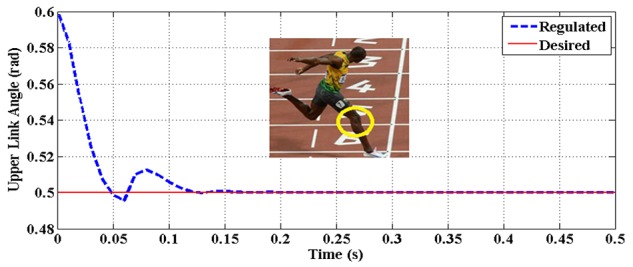
The upper link rotation angle (θ1) vs. time for case A.
Figure 6.
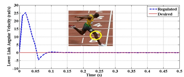
The lower link angular velocity θ̇2 vs. time for case A
Figure 4.
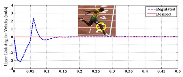
The upper link angular velocity θ̇2 vs. time for case A
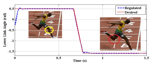
Figure 5.

The lower link rotation angle (θ2) vs. time for case A
It is immediately observed from the figure that the speed has decreased and the first constraint has happened at 0.5 rad. where the speed of the upper link is increased to 2.5 rad/sec. and the speed of the lower link is reduced to -5 rad/sec. (figures 3-6) Also, it can be seen that subsequent constraints have occurred rather moderately since the desired angles are determined as follows: θ2d>θ1d , which match with the real human walking cycle and gesture.
Case B: Both Backward and Forward Constraints Simulation
This state emerges while running very fast. Considering the forces applied to the lower link from the ground, its velocity increases acutely and performs the backward impact which in turn results in driving and moving the upper link towards forward direction. Here is an assumption that this situation usually occurs when θ2is negative and θ1-θ2>120. The results of this case have been shown in figures 7-10.
Figure 7.
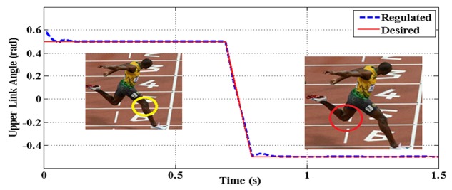
The upper link rotation angle (θ1) vs. time for case B
Figure 10.
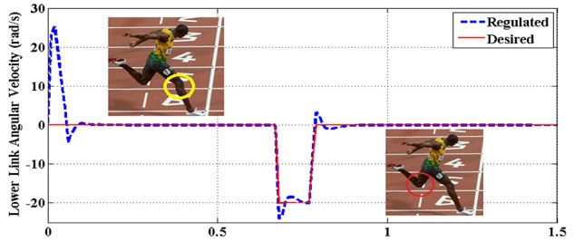
The lower link angular velocity θ̇2 vs. time for case B
Figure 8.
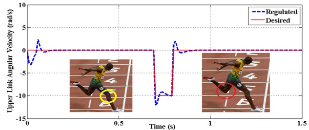
The upper link angular velocity θ̇1 vs. time for case B
Figure 9.
The lower link rotation angle (θ2) vs. time for case B
In the case of both backward and forward constraints simulation, the backward impact occurs at -0.5 rad and the speeds of the upper and lower links increase to 2.2 and 1.5 rad/sec., respectively. (figures 7-10).
Hereupon, the controller has regulated the angles to the desired ones, after sustaining the consecutive forward constraints; that altogether demonstrate the controller’s considerable potential.
Conclusion
The designed controller showed its great potential in regulating the natural motion of single leg locomotion, since it operated considerably well in various conditions of human walking. It is important to note that the controller performed suitably well and regulated the system accurately though the nonlinear constraint force has not been considered in the controller law.
By studying the human leg motion accurately during walking and particularly running, a new-determining perspective of the joint self-impact constraint effect, backward constraint, was simulated in this paper. Also, the leading character that this constraint plays in running and its effect on the efficiency and quality of that, proved here within the dynamic and control results that provided brighter insight into modeling more accurate single-leg locomotion simulations.
Conflict of Interest: None
References
- 1.Rau G, Disselhorst-Klug C, Schmidt R. Movement biomechanics goes upwards: from the leg to the arm. J Biomech. 2000;33:1207–16. doi: 10.1016/s0021-9290(00)00062-2. PubMed PMID: 10899329. [DOI] [PubMed] [Google Scholar]
- 2.Nandi GC, Ijspeert AJ, Chakraborty P, Nandi A. Development of Adaptive Modular Active Leg (AMAL) using bipedal robotics technology. Rob Auton Syst. 2009;57:603–16. doi: 10.1016/j.robot.2009.02.002. [Google Scholar]
- 3.Kagawa T, Uno Y. Necessary condition for forward progression in ballistic walking. Hum Mov Sci. 2010;29:964–76. doi: 10.1016/j.humov.2010.03.007. doi: 10.1016/j.humov.2010.03.007. PubMed PMID: 20655121. [DOI] [PubMed] [Google Scholar]
- 4.Neptune RR, Zajac FE, Kautz SA. Muscle force redistributes segmental power for body progression during walking. Gait posture. 2004;19:194–205. doi: 10.1016/S0966-6362(03)00062-6. doi: 10.1016/s0966-6362(03)00062-6. PubMed PMID: 15013508. [DOI] [PubMed] [Google Scholar]
- 5.Zajac FE, Neptune RR, Kautz SA. Biomechanics and muscle coordination of human walking: part II: lessons from dynamical simulations and clinical implications. Gait posture. 2003;17:1–17. doi: 10.1016/s0966-6362(02)00069-3. PubMed PMID: 12535721. [DOI] [PubMed] [Google Scholar]
- 6.Sangwan V, Taneja A, Mukherjee S. Design of a robust self-excited biped walking mechanism. Mech Mach Theory. 2004;39:1385–97. doi: 10.1016/j.mechmachtheory.2004.05.023. [Google Scholar]
- 7.Negnevitsky M. Artificial intelligence: A guide to intelligent systems. UK: Addison-Wesley; 2005. p. 415. [Google Scholar]
- 8.Pollard CD, Sigward SM, Powers CM. Limited hip and knee flexion during landing is associated with increased frontal plane knee motion and moments. Clin Biomech. 2010;25:142–6. doi: 10.1016/j.clinbiomech.2009.10.005. doi: 10.1016/j.clinbiomech.2009.10.005. PubMed PMID: 19913961; PubMed Central PMCID: PMC2815098. [DOI] [PMC free article] [PubMed] [Google Scholar]
- 9.Joseph M, Tiberio D, Baird JL, Trojian TH, Anderson JM, Kraemer WJ, et al. Knee valgus during drop jumps in National Collegiate Athletic Association Division I female athletes: the effect of a medial post. Am J Sports Med. 2008;36:285–9. doi: 10.1177/0363546507308362. doi: 10.1177/0363546507308362. PubMed PMID: 17977999. [DOI] [PubMed] [Google Scholar]
- 10.Nyland J, Burden R, Krupp R, Caborn DN. Whole body, long-axis rotational training improves lower extremity neuromuscular control during single leg lateral drop landing and stabilization. Clin Biomech. 2011;26(4):363–70. doi: 10.1016/j.clinbiomech.2010.11.021. doi: 10.1016/j.clinbiomech.2010.11.021. PubMed PMID: 21195516. [DOI] [PubMed] [Google Scholar]
- 11.Yu B, Kirkendall DT, Taft TN, Garrett WE. Lower extremity motor control-related and other risk factors for noncontact anterior cruciate ligament injuries. Instr Course Lect. 2002;51:315–24. PubMed PMID: 12064119. [PubMed] [Google Scholar]
- 12.Singh S, Mukherjee S, Sanghi S. Study of a self-impacting double pendulum. J Sound Vib. 2008;318:1180–96. doi: 10.1016/j.jsv.2008.05.001. [Google Scholar]
- 13.Slotine JJE, Li W. Applied nonlinear control. Englewood Cliffs, NJ: Prentice-Hall; 1991. p. 459. [Google Scholar]
- 14.Eghtesad M, Bazargan-Lari Y, Assadsangabi B. Stability Analysis and Internal Dynamics of MIMO GMAW Process. In: Chung MJ, Misra P, editors. Proceedings of the 17th IFAC World Congress (IFAC’08); 2008 July 6-11; Seoul, Korea. Seoul: COEX; 2008. pp. 14834–9. [Google Scholar]