Conventional differential interference contrast (DIC) microscope shows the two-dimensional distribution of optical phase gradient encountered along the shear direction between two interfering beams. Therefore, the contrast of DIC images varies proportionally to the cosine of the angle made by the azimuth of the phase gradient and the direction of wavefront shear. The image contrast also depends on the initial phase difference (bias) between the interfering beams. It is therefore necessary to examine the unknown object at several azimuth orientations and mechanically adjust bias of the DIC prism. [1,2].
To overcome the limitations of available systems, we recently developed an orientation-independent differential interference contrast (OI-DIC) microscope, which allows the bias to be modulated and shear directions to be switched rapidly without mechanically rotating the specimen or the prisms[3, 4]. However, the practical application of the OI-DIC technique used to require significant modification of a regular microscope. Recently we built a new compact OI-DIC beam-shearing assembly, which fits into the existing slot of research grade Olympus microscopes (http://www.olympusamerica.com). Dimensions of new OI-DIC assembly are exactly the same as dimensions of standard Olympus DIC prism (3.8” × 1.3” × 0.5”). Therefore, it does not require a microscope modification.
The assembly consists of two standard DIC prisms with a liquid crystal polarization rotator in between. Another liquid crystal cell is employed for modulating the bias. Within a second, the microscope captures a sets of raw DIC images at the orthogonal shear directions and different biases. In the report we will describe principles of computing the quantitative optical phase and phase gradient images. Newly developed OI-DIC technique can be used with available high-NA objective lenses providing the high-resolution imaging. It can also be combined with other imaging modalities such as fluorescence and polarization.
The new OI-DIC assembly improves image quality significantly in comparison to the previous system. It is not necessary to employ an additional optical component, which compensates a displacement of the second DIC prism from its designed position. There is no vignetting because of the longer path, which causes drop intensity at the image periphery. Previously it was necessary to cut the back aperture in order to keep the aberrations at the low level. With new assembly one can use the full aperture, which increases the resolution and decreases the exposure time.
Figure 1 shows a regular Olympus DIC prism U-DICTHR and the new OI-DIC beam-shearing assembly in the transmitted white light. There are two crossed polarizers at the entrance and exit of the beam. Both the DIC prism and the beam-shearing assembly split the input light into two output orthogonally polarized beams with a small shearing angle. The output beams create interference fringes, which are perpendicular to the shear plane. The left insert (a) in the picture shows that the shear plane of the regular DIC prism is parallel to the holder. The shear plane of the OI-DIC beam-shearing assembly is oriented at −45° in the OFF state (central insert (b)) and at +45° in the ON state (right insert (c)).
Figure 1.
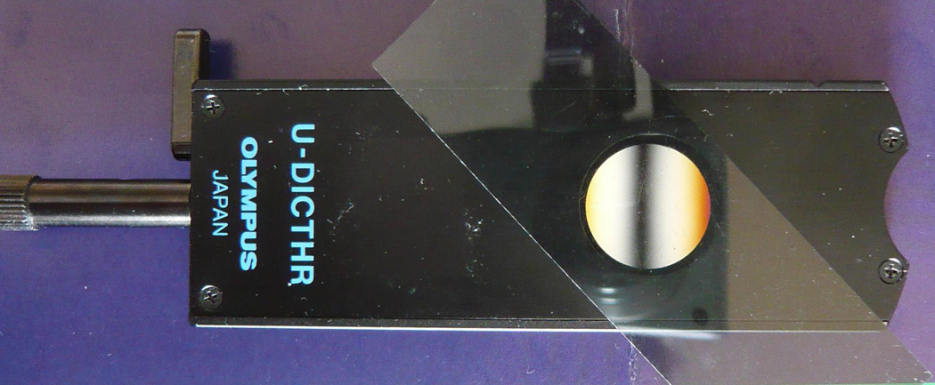
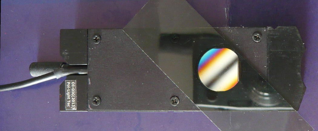
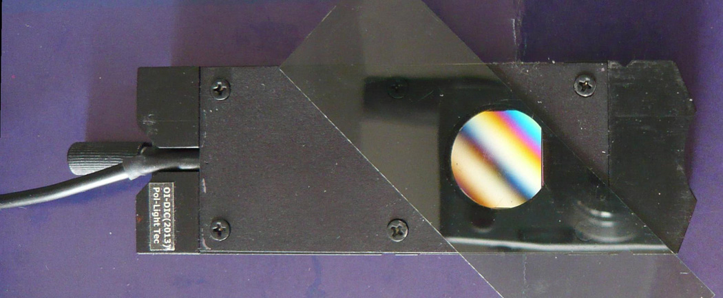
Regular Olympus DIC prism and OI-DIC beam-shearing assembly between crossed polarizers. (a) Regular DIC prism (shear plane at 0°); (b) OI-DIC assembly in OFF (shear plane at −45°); (c) OI-DIC assembly in ON (shear plane at 45°)
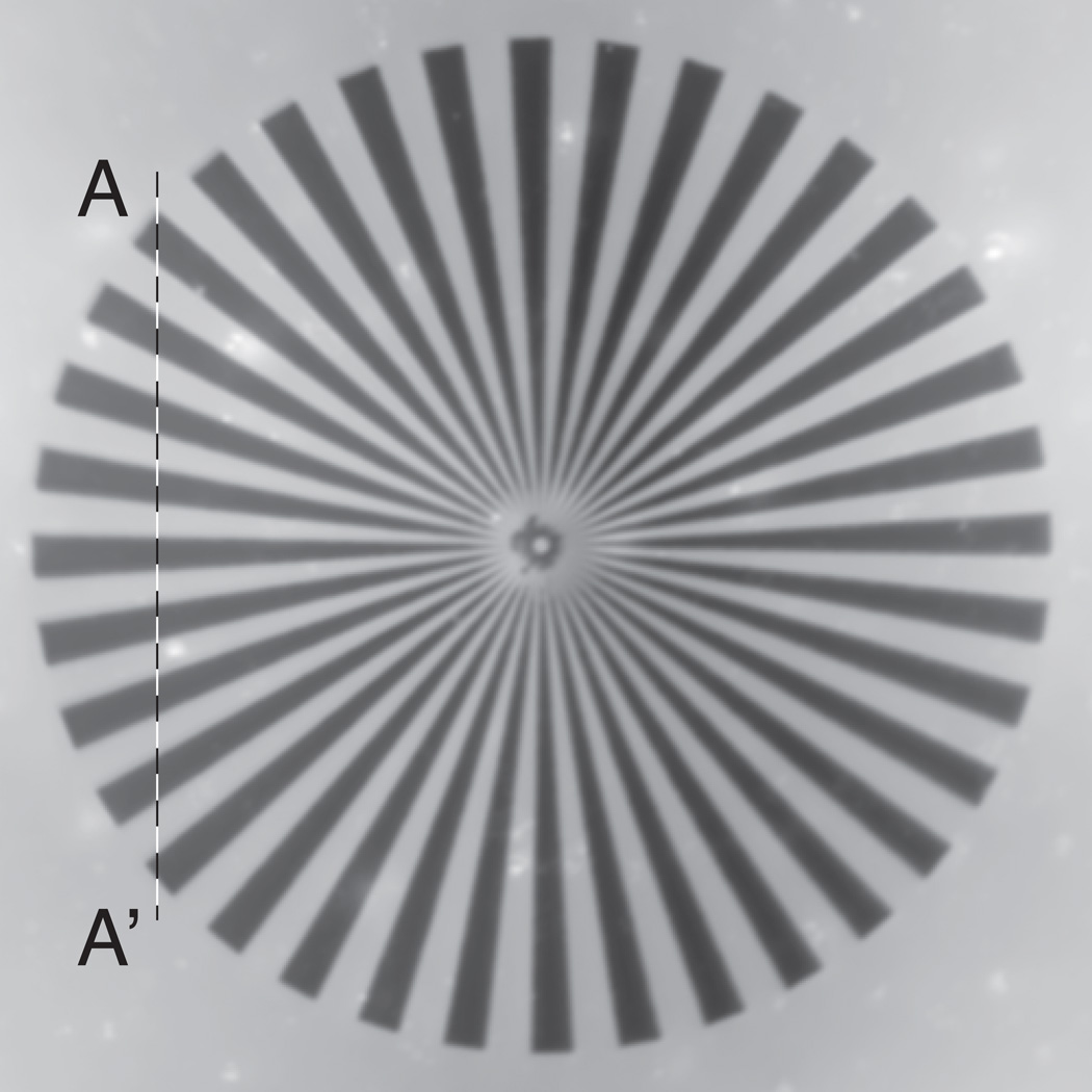
Figure 2 (a) presents an example of optical path map of 75-µm-diameter Siemens test star. The structure is created in a 90-nm-thick SiO2 film. The optical path amount is linearly proportional to the grey level, where white corresponds to the maximum of 100 nm. The optical path is a product of the film thickness and difference of refractive indices of film (SiO2) and wedge (air). Taking into account that refractive index of SiO2 film is 1.46 we can obtain the surface topography:
Height = optical path/(1.46−1).
Figure 2.
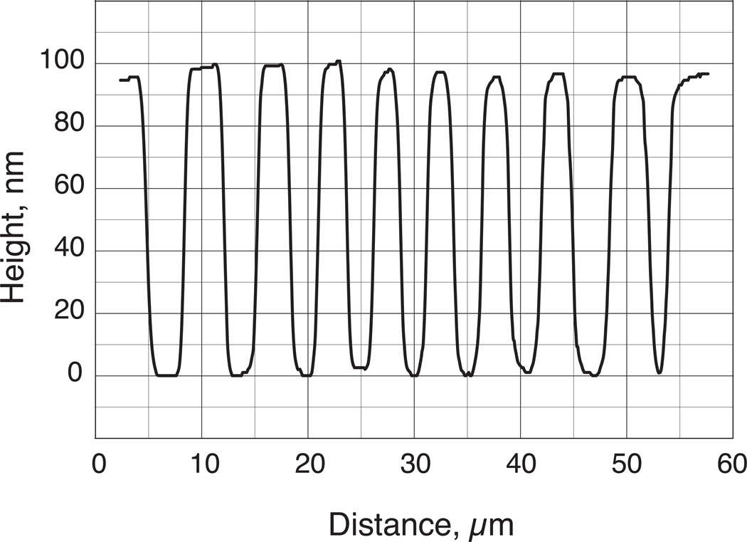
(a) Optical path map of calibrated man-made specimen Siemens test star (ceiling = 100nm); (b) the height section along line A-A’.
The distribution of height along section A-A’ is depicted in Figure 2 (b). As one can see the height of Siemens star wedges is around 97 nm.
Acknowledgments
This publication was made possible by Grant Number R01-GM101701 from the NIGMS/NIH.
References
- 1.Pluta M. Advanced light microscopy. Vol.2: Specialized methods. New York: Elsevier; 1989. [Google Scholar]
- 2.Inoué S, Spring KR. Videomicroscopy. 2nd ed. New York: Plenum Press; 1997. [Google Scholar]
- 3.Shribak M, Inoué S. Applied Optics. 2006;45:460–469. doi: 10.1364/ao.45.000460. [DOI] [PubMed] [Google Scholar]
- 4.Shribak M. The Journal of the Optical Society of America A. 2013;30:769–782. doi: 10.1364/JOSAA.30.000769. [DOI] [PMC free article] [PubMed] [Google Scholar]


