Medical microrobots are being widely studied for specific applications, such as targeted drug delivery, biopsy, hyperthermia, radioactive therapy, scaffolding, in-vivo ablation, stenting, sensing, and marking.1 These operations can be carried out with microrobots that offer a minimally invasive, accurately targeted, localized therapy via wireless intervention, such as magnetic fields.2 Numerous studies have examined the biomedical applications of magnetic actuation. Magnetic tubes and rotors have been developed for sensitive engines and fluid mixers driven by magnetic actuation.6 Among the various applications proposed for medical micro-devices, targeted drug delivery and micro-object transportation can be implemented using biocompatible and magnetically actuated agents. In previous studies, nanoparticles, magnetic particles, and nickel nanowires have been used as platforms for drug delivery.10 Helical and tubular lipid microstructures were developed as drug delivery platforms to overcome problems such as the poor loading capacity and propulsion efficiency.14 For helical microrobots,15 rotational motion induces translational velocity, which is one of the most effective propulsion methods in the low Reynolds number regime.21 To transport cells using magnetically actuated helical swimmers, a magnetized polymer helix, equipped with a cell gripper, is controlled by external magnetic fields.20 These helical microrobots have been used to transport a single microsphere in three dimensions. The microrobots were coated with a thin titanium (Ti) layer for better biocompatibility and affinity with the cells; this was confirmed by culturing cells on the helical microrobots. Similarly, microspheres can be transported in the flowing streams of microfluidic channels, which enable the microrobots to swim in the dynamic flow in the microfluidic channel.25
This paper reports the fabrication and characterization of three-dimensional (3D) porous micro-niches as a transporter using a photocurable polymer. The structures were coated with nickel (Ni) for magnetic actuation, and with Ti to ensure biocompatibility for possible in-vivo applications. The fabricated microrobots were rotated wirelessly and translated using a magnetic manipulator. Translational velocities were measured experimentally for different magnetic field gradients in the horizontal direction when the microrobots were aligned in vertical direction. Complex manipulations were also demonstrated by synchronized swimming and targeted tracking. Human embryonic kidney (HEK) 293 cells were cultured with the microrobot to demonstrate the feasibility of using microrobots as multi-cell transporters. Compared with previous microrobotic cargo devices, a well-defined 3D porous structure was used to culture multiple cells inside a structure with a customized pore size. A microrobot containing cells inside can be controlled magnetically in body fluids such as blood, urine, cerebrospinal fluid, or vitreous humor, to transport the cells to a target position in the body.
A scaffold is a porous 3D structure that is used for cell adhesion and mechanical support for tissue and organ regeneration.26 A 3D cell culture is important for sustaining the structural and functional complexities of the cells, because most in-vivo environments are 3D. Porous structures with controllable porosity have benefits over scaffolds with random pores, because they exhibit enhanced characteristics, such as the ability to produce the proper nutrient supply, uniform cell distribution, and high cell density.
Three-dimensional laser lithography offers excellent control over the geometry and porosity of the sample, as well as high resolution, and has been used recently to fabricate bio-scaffolds.30 In this technique, two laser beams are concentrated to form a single ellipsoidal spot, which is used as a building unit. The movement of a piezoelectric stage is controlled precisely to follow a pre-programmed path to partially expose the photoresist. A full 3D structure can be produced after removing the unexposed photoresist in a developer.
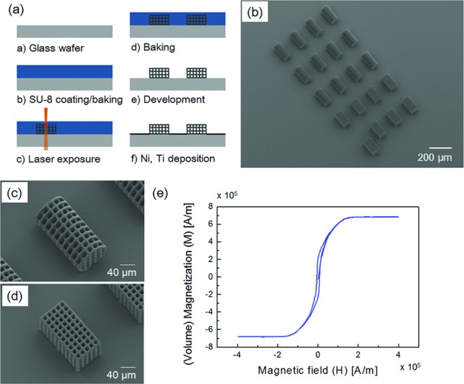
The proposed microrobots have been designed by determing the lateral distances between adjacent lines and the line width of the microrobots by considering the size of cells that would be placed inside the structure (generally 10–20 μm). The design parameters and their measured values are shown in Table 1. The optimum laser power, scan speed, and slice distance between scanning processes were defined by testing the sample structures (see Figure S1, Supporting Information). The appropriate writing speed and laser power for reasonable feature quality depends on the minimum bands of the designed structures. An overview of the fabrication process and scanning electron microscopy (SEM) images of the fabricated microrobots are shown in Figure 1. SU-8 was used as a high contrast epoxy-based photoresist to provide the mechanical stability required for complex, full 3D structures. The fabricated structures were coated with Ni, which can be magnetized and manipulated using magnetic fields. Finally, the structures were coated with Ti, a non-toxic material, to minimize cytotoxicity.
Table 1.
Designed and measured microrobot sizes
| Design(a)[μm] | I (I′) | II (II′) | III (III′) | IV (IV′) |
|---|---|---|---|---|
| Length | 153.98 | 144.20 | 154.40 | 156.60 |
| (157.00)(b) | (147.20) | (157.40) | (159.60) | |
| Diameter | 78.00 | 73.00 | 73.00 | 73.00 |
| (81.02) | (76.00) | (76.00) | (76.00) | |
| Line width | 1.98 | 1.98 | 1.98 | 1.98 |
| (5.08) | (5.08) | (5.08) | (5.08) | |
| Pore size | 13.22 | 16.00 | 20.00 | 24.00 |
| (10.20) | (13.00) | (17.00) | (21.00) |
Each microrobot design has two shapes: cylindrical (I, II, III, and IV), and hexahedral (I′, II′, III′, and IV′). The diameter of the cylindrical shape of the microrobots corresponds to the width or height of the hexahedral-shaped microrobots;
The measured values for Type I were actually measured. The other values, Type I′, II, II′, III, III′, IV, and IV′ are the expected values based on the Type I measurement (see Figure S2).
Figure 1.

a) Overview of the microrobot fabrication process. b) Scanning electron microscopy (SEM) image of the fabricated microrobots. c) Enlarged SEM image of a cylindrical-shaped microrobot. d) Enlarged SEM image of a hexahedral-shaped microrobot. e) Magnetization of the microrobots per unit volume of nickel.
High saturation magnetization and low coercivity are desired for microrobot movement. Figure 1e shows the measured magnetization per unit volume for nickel using Physical Property Measurement System (PPMS; Quantum Design, US). The measured saturation magnetization per volume was 686 kA m−1 (686 emu cm−3) and the coercivity was 5 kA m−1 (62.83 Oe), which suggested that the deposited nickel has a perfect ferromagnetic nature. The size of the microrobots affects their motion. Increasing the microrobot size with a fixed magnetic material volume would decrease the velocity as the hydrodynamic drag force is increased. However, coating the structure with a greater volume of magnetic material increases the driving force, while the drag force does not change significantly. For example, doubling the magnetic material thickness will roughly double the magnetic driving force, while the drag force remains constant. A higher driving force can also lead to better control over the microrobot.
Rotational and translational locomotion of the microrobot require a magnetic torque and force on the magnetized structure.34 The magnetic material on the surface of an anisotropic structure induces rotational motion, and the structure aligns with the external magnetic field (B) direction. Magnetic torque and force can be calculated using the magnetic field (B) and magnetic field gradient (∇B) as follows:
| (1) |
| (2) |
where V is the volume of the magnetized object and M is the uniform magnetization of the magnetic material.
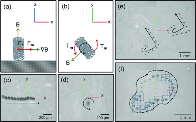
The microrobot was manipulated using a customized magnetic actuation system (Minimag; Aeon Scientific, Switzerland). In this system, the magnetic field was generated by the linear superposition of individual fields from eight coils carrying different currents.38 The microrobot was controlled in deionized (DI) water in a plastic container, with five degrees of freedom (5-DOF): three translational (x, y, and z) and two rotational (around the z- and x-axes) DOF. An external magnetic field was applied in the z-direction to align the principal axis of the microrobot in the same direction, as shown in Figures 2a and c. Then, a gradient field was used to translate the microrobot along the x-axis direction. The maximum generated magnetic field was 800 mT m−1. Figures 2b and d show the rotation of the microrobot with respect to the z-direction, with a rotation frequency of 3 Hz. Figures 2c and d show time-lapsed images of the cylindrical microrobot undergoing translational and rotational motion (see Videos S1 and S2, Supporting Information). The microrobots were controlled along complicated trajectory lines to demonstrate synchronized swimming and targeted control behaviors, as shown in Figures 2e and f (see Videos S3 and S4).
Figure 2.

Schematic description of the a) translational motion and b) rotational motion of the cylindrical microrobot. Time-lapsed images of the cylindrical microrobots c) translational motion (see Video S1) and d) rotational motion (see Video S2). e) Synchronized swimming with rolling motion (see Video S3). f) Targeted control with rotational motion (see Video S4).
There are two resistive forces working against the motion of the microrobot: the drag force and surface friction. For manipulation, the input magnetic force must overcome these resistive forces. A magnetic force in the z-direction was also required to compensate for the weight of the microrobot. The translational motion dynamics can be modeled as
| (3) |
where Fm is the magnetic force, Fr is the resistive force (including the surface friction and drag force), Fg is the gravitational force, m is the mass, and v is the translational velocity of the microrobot.
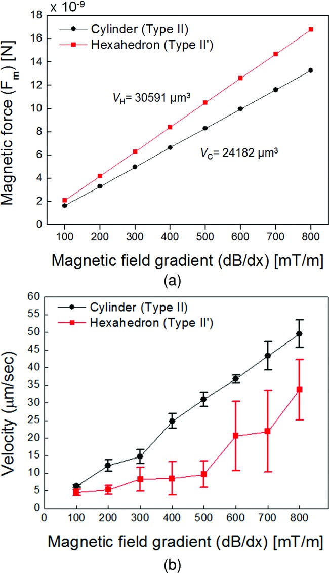
The microrobot was aligned with the z-axis by applying an external magnetic field along the same axis, as shown in Figure 2a. Magnetic torque can be calculated using Equation (1) for rotational motion of the cylindrical microrobot as depicted in Figure 2b. The magnetic forces for the two types of microrobot were calculated using Equation (2), as shown in Figure 3a. The driving magnetic force is proportional to the external magnetic field gradient and volume of nickel. Figure 3b shows the mean value of the translational velocity of the microrobots from five trials as a function of the magnitude of the applied magnetic field gradient. When an external field gradient of 800 mT m−1 was applied in the x-direction, the translational velocity of the microrobot was approximately 50 μm s−1 for the cylindrical microrobot (≈1/3 body lengths per second). The results showed a linear dependence of the required magnetic field gradient on the translational velocity for the cylindrical-shaped microrobots. However, for the hexahedral-shaped microrobots, the relationship between the translational velocity and input force was nonlinear.
Figure 3.

a) Calculated magnetic force on the microrobots, along with their volume of nickel and magnetic field gradient. b) Translational velocity of the cylindrical and hexahedral microrobots in the x-direction as a function of the applied magnetic field gradient. The microrobots were aligned with the z-direction. (Note that these data correspond to Figures 2a and c for the cylindrical robot.)
Since the Reynolds number was low under these experimental conditions, we could consider the microrobot motion to be quasi-static. For constant velocity motion in the x-direction, from Equation (3), the magnetic and resistive forces are balanced and there is no gravitational force in the horizontal direction. The resistive force consists of the drag and friction forces. The drag force is linearly dependent on the microrobot velocity in a low-Reynolds number flow. Figure 3b indicates that a cylindrical microrobot has a higher velocity than a hexahedral microrobot for the same magnetic field gradient. For the hexahedral microrobot, a nonlinear relationship was evident between the translational velocity and the magnetic field gradient; this could be attributed to the nonlinear characteristics of the velocity and resistive force. Since the drag force is linear with respect to the velocity, the friction force plays a greater role in the nonlinear character of the hexahedral microrobot.
The surface area of the hexahedral microrobot was larger than that of the cylindrical microrobot. Since Ni was deposited uniformly on the surfaces of both microrobots, the hexahedral microrobot had a larger volume of nickel. Therefore, the magnetic moment of the hexahedral microrobot was greater than that of the cylindrical microrobot, which implies that a greater magnetic force needed to be applied to the hexahedral microrobot for a specific magnetic field gradient (Equation (2) and Figure 3a). However, the hexahedral microrobot exhibited a lower translational velocity, which might have been caused by a higher resistive force. Therefore, the cylindrical microrobot design is favorable for minimizing the resistive force against manipulation.
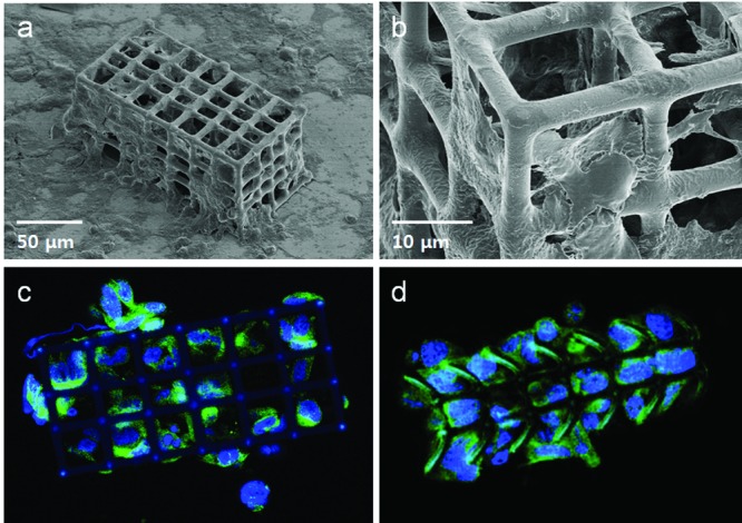
In this study, HEK 293 cells were cultured inside porous microrobots.39 Figure 4 shows SEM and confocal microscopy images of the microrobots. The HEK 293 cells were affixed using paraformaldehyde solution, before SEM inspection, after 96 h of cell culture. Filopodia formed during cell migration, as depicted in the enlarged SEM image (Figure 4b), which indicates that the cells interacted with the microrobots. The microrobots were coated with poly-l-lysine (PLL) before cell culture. PLL is a synthetic amino acid chain that is positively charged and used widely as a coating material to enhance cell attachment. In addition, PLL does not react in the staining assay. Since the cell surfaces are negatively charged, cells attach to the PLL via ionic bonding. Since PLL is a synthetic molecule, it does not stimulate cells cultured on it biologically. Therefore, we can consider the microrobot as a supporting structure and PLL simply as a linking material for cells.40 The results revealed that the microrobot material was not cytotoxic to the myoblasts, as indicated by the ease in adhesion, migration, and proliferation of the cells over the structure. The confocal microscopy images were obtained after staining the cells inside the microrobots.
Figure 4.

a) SEM image of a hexahedral microrobot after cell culture and b) an enlarged SEM image. Filopodia are clearly shown in this enlarged image. Confocal microscope images of the c) hexahedral and d) cylindrical microrobots after staining of the cells.
In conclusion, we have demonstrated multifunctional microrobots for targeted cell delivery using 3D laser lithography. The microrobots were coated with Ni and Ti layers as magnetic and biocompatible materials, respectively. The fabricated porous 3D structures were used for 3D cell cultures of HEK 293 cells. The microrobots were controlled in a magnetic field for targeted transportation. The materials used for the structures were not cytotoxic to myoblasts, as the cells readily adhered, migrated, and proliferated over the structure. The optimum fabrication parameters, established for the proposed microrobot structures, can be easily customized for different cell types. Microrobots with cylindrical and hexahedral shapes were manipulated in DI water by applying an external magnetic field gradient in the x-direction when they were aligned with the z-axis. We also have demonstrated more complicated trajectories of these microrobots with the manipulator. This work has disclosed the feasibility of the proposed porous microrobot as a 3D cell transportation system or drug delivery system, with targeted micromanipulation for in-vivo applications.
Acknowledgments
We thank the FIRST lab of ETH Zurich for technical support. The authors are also grateful to Junman Lee (DGIST) for help with the microrobot design, Simone Schuerle (ETH Zurich) for technical support with magnetic manipulation, Jiyeon Park (DGIST) for assistance with the SEM inspection, Eunjung Kim (Kyungbuk National University) for suggestions regarding cell cultures, and Seungyeong Im (DGIST) for help with the sample preparation for confocal microscope inspection of the dyed cells. Part of the funding for this research was provided by a National Research Foundation of Korea grant funded by the Korean Government (2011-0013638) and by the DGIST R8D Program of the Ministry of Education, Science and Technology of Korea (13-BD-0403 and 12-1-HRA-01).
Note: The license of this manuscript was updated after initial online publication.
Experimental Section
Microrobot fabrication: A 3 cm glass wafer was cleaned in an ultrasonic bath, using isopropyl alcohol (IPA) to remove any residual dust or organics. SU-8 (1.25 mL NANO SU-8 100, MicroChem, US) was spin-coated onto the glass wafer in two steps: 500 rpm for 10 s with a speed ramp of 100 rpm s−1, and 1000 rpm for 30 s with a speed ramp of 300 rpm s−1. This produced a 100 μm-thick layer of SU-8 on the glass wafer surface. Then, the substrate was baked using a two-step process at 65 °C for 10 min, followed by 95 °C for 30 min. Then, the substrate was cooled to room temperature for 10 min. Two-photon polymerization (TPP) and 3D laser lithography were conducted to polymerize the designed structures partially, followed by a pre-development bake at 65 °C for 1 min and a 95 °C bake for 10 min. After cooling the substrate, mr-Dev 600 (micro resist technology GmbH, Germany) was used to develop the SU-8 for 20 min. To deposit a Ni/Ti bilayer on the polymer microrobots, 150 nm of Ni was deposited as a magnetic material using e-beam evaporation; the chuck was rotated and tilted to reduce the shadowing effect. This was followed by deposition of a 20 nm-thick layer of Ti to provide biocompatibility.
Supporting Information
Supporting Information is available from the Wiley Online Library or from the author.
References
- Nelson BJ, Kaliakatsos IK, Abbott JJ. Annu. Rev. Biomed. Eng. 2010;12:55. doi: 10.1146/annurev-bioeng-010510-103409. [DOI] [PubMed] [Google Scholar]
- Grady MS, Howard MA, III, Molloy JA, Ritter RC, Quate EG, Gillies GT. Med. Phy. 1990;17:405. doi: 10.1118/1.596520. [DOI] [PubMed] [Google Scholar]
- Park S, Cha K, Park J. Int. J. of Adv. Rob. Sys. 2010;7:91. [Google Scholar]
- Bergeles C, Kratochvil BE, Nelson BJ. IEEE Tran. On Rob. 2012;28:798. [Google Scholar]
- Ergeneman O, Chatzipirpiridis G, Pokki J, Toro MM, Sotiriou GA, Rodrígez SM, Sánchez JF, Gutiérrez AF, Pané S, Nelson BJ. IEEE Tran. on Biomed. Eng. 2012;59:3104. doi: 10.1109/TBME.2012.2216264. [DOI] [PubMed] [Google Scholar]
- Zhao G, Sanchez S, Schmidt OG, Pumera M. Chem. Commum. 2012;48:10090. doi: 10.1039/c2cc35671f. [DOI] [PubMed] [Google Scholar]
- Zhao G, Pumera M. Langmuir. 2012;10:1021. [Google Scholar]
- Yamanishi Y, Lin Y, Arai F. Proc. IEEE/RSJ Int. Conf. Intelligent Robots and Systems. 2007 [Google Scholar]
- Petit T, Zhang L, Peyer KE, Kratochvil BE, Nelson BJ. Nano Lett. 2012;12:156. doi: 10.1021/nl2032487. [DOI] [PubMed] [Google Scholar]
- Anirudhan TS, Sandeep S. J. Mat. Chem. 2012;22:12888. [Google Scholar]
- Sivaraman K, Kellenberger C, Pané S, Ergeneman O, Lühmann T, Luechinger NA, Hall H, Stark WJ, Nelson BJ. Biom. Microdev. 2012;14:603. doi: 10.1007/s10544-012-9639-6. [DOI] [PubMed] [Google Scholar]
- Hu C, Tercero C, Ikeda S, Fukuda T, Arai F, Negoro M. Proc. IEEE/RSJ Int. Conf. Intelligent Robots and Systems. San Francisco, California: 2011. [Google Scholar]
- Zhang L, Petit T, Peyer KE, Nelson BJ. Nanomedicine: NBM. 2012;8:1074. doi: 10.1016/j.nano.2012.03.002. [DOI] [PubMed] [Google Scholar]
- Schuerle S, Pané S, Pellicer E, Sort J, Baró MD, Nelson BJ. Small. 2012;8:1498. doi: 10.1002/smll.201101821. [DOI] [PubMed] [Google Scholar]
- Peyer KE, Tottori S, Qiu F, Zhang L, Nelson BJ. Chem.- A Eur. J. 2012;19:28. doi: 10.1002/chem.201203364. [DOI] [PubMed] [Google Scholar]
- Zhang L, Peyer KE, Nelson BJ. Lab Chip. 2010;10:2203. doi: 10.1039/c004450b. [DOI] [PubMed] [Google Scholar]
- Zhang L, Abbott JJ, Dong LX, Kratochvil BE, Bell DJ, Nelson BJ. Appl. Phys. Lett. 2009;94:064107. [Google Scholar]
- Zhang L, Abbott JJ, Dong LX, Peyer KE, Kratochvil BE, Zhang HX, Bergeles C, Nelson BJ. Nano Lett. 2009;9:3663. doi: 10.1021/nl901869j. [DOI] [PubMed] [Google Scholar]
- Peyer KE, Zhang L, Nelson BJ. Nanoscale. 2013;5:1259. doi: 10.1039/c2nr32554c. [DOI] [PubMed] [Google Scholar]
- Tottori S, Zhang L, Qiu F, Krawczyk KK, Franco-Obregón A, Nelson BJ. Adv. Mat. 2012;24:811. doi: 10.1002/adma.201103818. [DOI] [PubMed] [Google Scholar]
- Abbott JJ, Nagy Z, Beyeler F, Nelson BJ. IEEE Rob. Auto. Mag. 2007;14:92. [Google Scholar]
- Purcell EM. Amer. J. Phys. 1977;45:3. [Google Scholar]
- Abbott JJ, Peyer KE, Lagomarsino MC, Zhang L, Dong L, Kaliakatsos IK, Nelson BJ. Int. J. Robot. Res. 2009;28:1434. [Google Scholar]
- Ghanbari A, Bahrami M. J. Intel. Rob. Sys. 2011;63:399. [Google Scholar]
- Sanchez S, Solovev AA, Harazim SM, Schmidt OG. J. Am. Chem. Soc. 2011;133:701. doi: 10.1021/ja109627w. [DOI] [PubMed] [Google Scholar]
- Tsang VL, Bhatia SN. Adv. Drug Deliv. Rev. 2004;56:1635. doi: 10.1016/j.addr.2004.05.001. [DOI] [PubMed] [Google Scholar]
- Owen SC, Shoichet MS. J. Biomed. Mater. Res. A. 2010;94A:1321. doi: 10.1002/jbm.a.32834. [DOI] [PubMed] [Google Scholar]
- Subia B, Kundu J, Kundu SC. In: Tis. Eng. 2. Eberli D, editor. Intech; 2010. [Google Scholar]
- Abdelaal OA, Darwish SM. World Acad. of Sci., Eng. and Tech. 2011;59:577. [Google Scholar]
- Wittig R, Waller E, Freymann G, Steiner R. J. Laser Appl. 2012;24:042011. [Google Scholar]
- Kapyla E, Aydogan1 DB, Virjula S, Vanhatupa S, Miettinen S, Hyttinen J, Kellomaki M. J. Micromech. Microeng. 2012;22:115016. [Google Scholar]
- Klein F, Striebel T, Fischer J, Jiang Z, Franz CM, Freymann G, Wegener M, Bastmeyer M. Adv. Mater. 2010;22:868. doi: 10.1002/adma.200902515. [DOI] [PubMed] [Google Scholar]
- Klein F, Richter B, Striebel T, Franz CM, Freymann G, Wegener M, Bastmeyer M. Adv. Mater. 2011;23:1341. doi: 10.1002/adma.201004060. [DOI] [PubMed] [Google Scholar]
- Abbott JJ, Ergeneman O, Kummer M, Hirt AM, Nelson BJ. IEEE Tran. Rob. 2007;23:1247. [Google Scholar]
- Pawashe C, Floyd S, Sitti M. Int. J. Robot. Res. 2009;28:1077. [Google Scholar]
- Ghanbari A, Bahrami M, Nobari MRH. Phys. Rev. E. 2011;83:046301. doi: 10.1103/PhysRevE.83.046301. [DOI] [PubMed] [Google Scholar]
- Liu C. Foundations of MEMS. Englewood Cliffs, NJ: Prentice-Hall; 2005. [Google Scholar]
- Schuerle S, Erni S, Flink M, Kratochvil BE, Nelson BJ. IEEE Tran. Magn. 2013;49:321. [Google Scholar]
- Smith BS, Yoriya S, Johnson T, Popat KC. Acta. Biomater. 2011;7:2686. doi: 10.1016/j.actbio.2011.03.014. [DOI] [PubMed] [Google Scholar]
- Mazia D, Schatten G, Sale W. J. Cell. Biol. 1975;66:198. doi: 10.1083/jcb.66.1.198. [DOI] [PMC free article] [PubMed] [Google Scholar]
Associated Data
This section collects any data citations, data availability statements, or supplementary materials included in this article.


