Abstract
The traditional approaches of estimating heterogeneous properties in a soft tissue structure using optimization based inverse methods often face difficulties because of the large number of unknowns to be simultaneously determined. This article proposes a new method for identifying the heterogeneous anisotropic nonlinear elastic properties in cerebral aneurysms. In this method, the local properties are determined directly from the pointwise stress-strain data, thus avoiding the need for simultaneously optimizing for the property values at all points/regions in the aneurysm. The stress distributions needed for a pointwise identification are computed using an inverse elastostatic method without invoking the material properties in question. This paradigm is tested numerically through simulated inflation tests on an image-based cerebral aneurysm sac. The wall tissue is modeled as an eight-ply laminate whose constitutive behavior is described by an anisotropic hyperelastic strain-energy function containing four parameters. The parameters are assumed to vary continuously in the sac. Deformed configurations generated from forward finite element analysis are taken as input to inversely establish the parameter distributions. The delineated and the assigned distributions are in excellent agreement. A forward verification is conducted by comparing the displacement solutions obtained from the delineated and the assigned material parameters at a different pressure. The deviations in nodal displacements are found to be within 0.2% in most part of the sac. The study highlights some distinct features of the proposed method, and demonstrates the feasibility of organ level identification of the distributive anisotropic nonlinear properties in cerebral aneurysms.
Keywords: Parameter identification, cerebral aneurysm, pointwise identification method, inverse elastostatics, nonlinear membrane
1 Introduction
Cerebral aneurysms are focal dilatations of the intracranial arterial wall that usually develop in or near the circle of Willis. Non-complicated cerebral aneurysms are typically thin-walled. Their diameters range from a few to a few tens of millimeters while the wall thicknesses range from tens to hundreds of micrometers [1, 2]. In the service environment these lesions are best described as elastic membranes. Rupture of aneurysms is the leading cause of subarachnoid hemorrhage. Traditionally, rupture risk assessment was based primarily on size and shape [3, 4, 5, 6, 7, 8, 9, 10], while mechanical factors such as stress and strain have also been submitted [11, 12, 13, 14].
Fundamental to the stress analysis is the constitutive behavior of wall tissue. However, delineating the constitutive equation of aneurysm tissue, in particular, experimental determination of the material parameters, presents some significant challenges. The lesion wall typically consists of multiple layers of type I and III collagen fibers with varying orientations [15, 16], giving rise to an anisotropic heterogeneous nonlinear behavior at the continuum level. Reports on cerebral aneurysm tissue property have been scarce. Earlier studies focused mainly on structural property (e.g., pressure-volume relation) [17], or uniaxial and biaxial tissue properties exercised strips and sheets [18, 19]. These studies revealed the nonlinear nature of the wall tissue but fell short to delineating the anisotropic and heterogeneous behavior. Due to the size limitation, it is difficult, if not impossible, to characterize the heterogeneous properties using cut specimens; instead, optimization-based inverse methods seem to be more suitable. It is worth noting that if a lesion is more or less axisymmetric, then the axisymmetric inflation test [20, 21, 22, 23, 24], also an non-invasive approach, could also be a viable alternative. Humphrey’s group characterized cerebral aneurysms wholly harvested from cadaver [1]. They utilized an inverse finite element approach on subdomains [25, 26] assuming the tissue property is homogeneous over each subdomain. In this manner, they established the regional best-fit material parameters in a Fung-type strain-energy. Their work remains to this date the most complete report on the heterogeneous properties in real cerebral aneurysms.
Kroon and Holzapfel [27] reported a numerical study in which an idealized aneurysm were inversely characterized as a whole, without subdomain partition. The constitutive equation contains four parameters; each varies spatially in a prescribed manner. The domain was discretized into 288 elements, and the parameters were assumed constant element-wise, giving a total of 865 parameters describing the heterogeneous behavior. Using a hierarchical iteration approach, they identified the parameters all together and obtained a good fit. While successful, the work was based on the traditional optimization approach which requires all unknown parameters to be simultaneously determined. The size of the optimization problem depends on the mesh; the robustness and effectiveness of this approach remain unclear if the model size or constitutive complexity is further increased.
Recently, the present authors proposed a new pointwise identification method (PWIM) for characterizing nonlinear membranes [28, 29]. The method is markedly different from the usual optimization approach. In PWIM, the stress and strain distributions are obtained prior to identification. Consequently, the regression problem is formulated locally at each individual material point, and the material properties are determined point-wisely in parallel. The method hinges critically on the membrane inverse elastostatic method [14] for stress computation; the inverse method exploits the property of static determinacy in membrane structures and solves the membrane stress without invoking the material property in question. Therefore, PWIM is expected to be able to sharply characterize heterogeneous properties. In addition, the method avoids the coupled iteration between stress analysis and parameters regression and thus significantly reduces the computation cost.
The purpose of this paper is to test the feasibility of PWIM in identifying the heterogeneous properties of cerebral aneurysms. In [28, 29], we have verified the method numerically in the context of isotropic nonlinear material and validated the method physically using inflation tests on balloons which were deemed isotropic and homogeneous at the end. In this work, an anisotropic heterogeneous nonlinear aneurysm model is considered. We focus on in vitro setting where it is reasonable to expect that the unloaded stress-free configuration can be obtained. In vivo application will require one to determine, simultaneously with the material parameters, the unknown stress-free configuration. We have proposed an approach to this problem and tested the concept in isotropic material; but the applicability to complicated anisotropic materials remains to be investigated. Research in this direction is underway in the authors’ group. In this work, we utilize finite element method to simulate inflation tests, and take the predicted configurations as input to inversely establish the material parameters. The geometry of the considered sac is adapted from CT images. The wall material tissue is assumed to follow an anisotropic hyperelastic strain energy function proposed by Kroon and Holzapfel [30]. To introduce heterogeneity, the stiffness parameters and the symmetry axes are assigned to vary spatially over the sac. The aneurysm model, although not entirely realistic, incorporates many essential features and some best known information about cerebral tissue.
2 Background
2.1 Static determinacy in membrane structures
In general, the stress in a deformable solid depends on the applied load, the boundary condition, the geometry, and the material property. There is, nevertheless, a class of problems in which the stress depends only on the load, the boundary condition and the geometry, but not the material property. Systems as such are called statically determined. Static determinacy plays a crucial role in experimental characterization of elastic properties because the stress can be obtained independently of material parameters in question. The uniform stress field, for example, is a fundamental type of statically determined system and this stress state underlines the commonly used specimen test.
The method we pursue exploits another family of statically determined system, namely pressurized curved membranes. It is well-known that a pressurized curved membrane is statically determined, or at least approximately so in the sense explained later. A prominent example is a pressurized spherical membrane, in which the wall tension follows the Laplace formula T = pR/2 (T: the wall tension, p: the pressure, R: the current radius) which notably does not involve material property. This unique feature stems from the characteristics of membrane equilibrium. A membrane is a thin material body of which the thickness is much smaller than the other dimensions. Due to thinness, a membrane has negligible resistance to bending and transverse shear. Thus, the stress is locally in a plane stress state, having three nonzero components. When the surface is curved, the equilibrium equation gives rise to three component equations [14], and thus the equilibrium equations are closed. If the membrane is subjected to traction boundary only, the wall stress is completely independent of the material properties. The scenario is slightly different at the presence of displacement boundary constraints. In this case, the equilibrium equations are no longer closed and constitutive equations are required to solve the equilibrium problem. However, if the membrane is sufficiently deep (say the height is comparable to the diameter), the material influence on the stress field is expected to exist in boundary regions nears the constrained edges. This phenomenon has been discussed analytically, among others, by Rossettos [31]. He derived the membrane solutions in axisymmetric systems under various boundary conditions. For clamped membranes the stress field was shown to exhibit a boundary layer phenomenon; outside a thin boundary layer the stress is asymptotic to the material-independent static solution. Although no analytical results exist for general cases, numerical simulations by our group demonstrated this boundary layer phenomenon in sac-like structures of general shape [14, 32]. The stress outside a boundary layer is massively insensitive to material properties. In this case, the structure can be regarded as approximately static-determinate and, for practical purpose, the stress field in regions away from displacement boundary can be regarded as material independent.
2.2 Inverse elastostatics for membranes
The present authors have developed inverse finite element formulations for membrane and shell structures [14, 33] based on the concept of inverse elastostatic analysis [34, 35, 36, 37]. The inverse method formulates the weak form directly on a known deformed configuration. The stress in the given deformed state is determined by inversely finding an stress-free configuration that can be brought back to the given deformed configuration upon the application of the load. For membrane and shell structures, a distinct advantage of the inverse method is that it can maximally capitalize on the static determinacy of the system. One can use assumed material models to compute the stress and obtain accurate stress solutions. In the context of material characterization, this enables the acquisition of stress data without invoking the material property in question and thus, separates the stress analysis from parameter regression.
The inverse finite element formulation for membrane problems was presented in [14]. Briefly, the finite element formulation starts with the standard weak form, the same one for forward analysis:
| (1) |
Here, Ω is the current surface, ∂Ωt is the boundary upon which the traction t̄ is applied, δx is any kinematically admissible variation to the current configuration, and b is the applied surface force. For a membrane under a transverse pressure p, b = pn where n is the unit surface normal. In the inverse setting, the current configuration is prescribed; the weak form is solved for the material point position X in the stress-free reference configuration, which enters the system through the constitutive equation. Details of the implementation are contained in [14]. In the present application, an auxiliary elasticity model is introduced to facilitate the inverse stress analysis. Due to static determinacy, the model is expected to have a minimal influence on the stress solution.
2.3 Pointwise identification method
The pointwise identification method (PWIM) [28, 29] works as follows. Suppose that a series of deformed configurations of a membrane sac and the corresponding pressures are measured. Then, the stress distribution in each configuration is computed individually using the inverse elastostatic method, which takes the corresponding geometry and the pressure as input. As discussed previously, the method introduces an auxiliary material model, but the computed stress in regions sufficiently distanced from boundary constraints is expected to be independent of (in practice, insensitive to) the applied model. In implementation, the sensitivity to material parameters will be checked numerically and parameter regression will be performed only in regions where the stress is deemed insensitive. The membrane strain is determined from the measured surface deformation. In this manner, one acquires at every point in the mesh a set of stress-strain data which embodies the local property. The stress-strain data are subsequently fit point-wisely to a proper constitutive model to delineate the local property. In [29], we have validated this paradigm experimentally using a hyperelastic balloon.
3 Method
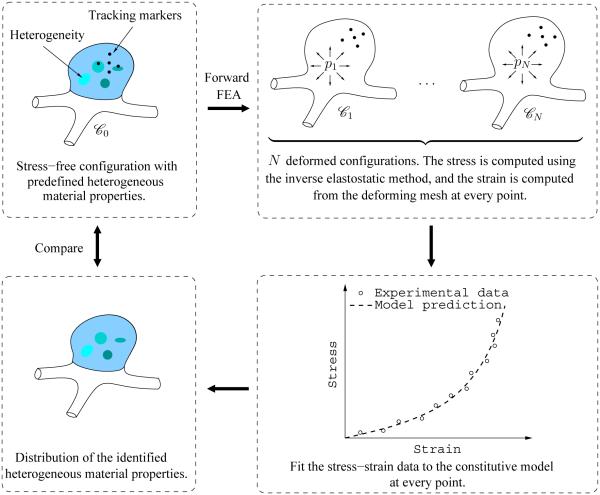
A virtual (numerical) test was conducted to demonstrate and evaluate the utility of PWIM in cerebral aneurysms. The procedure is illustrated in Figure 1. The aneurysm sac considered in this work was constructed from CT images. The finite element model is shown in Figure 2 including the initial configuration and the deformed configuration at 200 mmHg blood pressure. The finite element mesh consists of 885 elements and 916 nodes. Clamped boundary condition was applied at the neck of the aneurysm, to mimic in vitro inflation tests. The wall tissue was modeled as an anisotropic hyperelastic material described by a laminate model, and the material properties were assigned to vary spatially to introduce heterogeneity. The assumed distribution of heterogeneous elastic property is referred to as the reference distribution. Taking this model, we simulated an inflation motion by performing a series of quasistatic finite element analyses. The obtained deformed configurations were considered as experimentally observed configurations. Subsequently, we used the displacement and pressure data to inversely establish the material parameters. The parameter identification was carried out in a subregion where the inverse stress solution was deemed free from boundary effect. To assess the identification results, the identified distribution was compared to the reference distribution. A forward verification was conducted by comparing the nodal displacements obtained from the reference and the identified parameters at a pressure not used in the regression.
Figure 1.
Schematic of the validation procedure.
Figure 2.
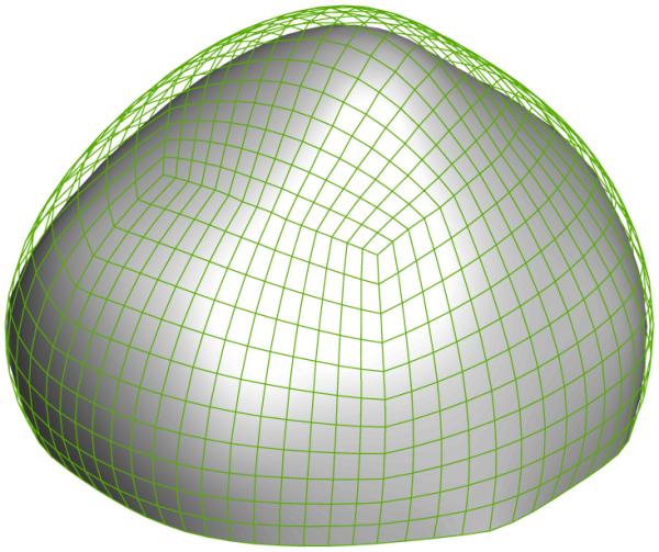
The reference configuration (solid surface) and a deformed configuration (mesh) at 200 mmHg of the aneurysm sac.
3.1 Material model
Strain energy function
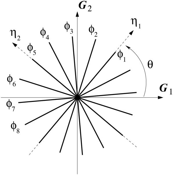
Cerebral aneurysm wall consists of primarily 7-8 layers of type I and III collagen fibers with varying orientations that form two-dimensional networks [15]. At the continuum level, the tissue is typically described by a single strain energy function that takes into account collectively the properties and microstructure of the constituents. Kroon and Holzapfel [30] proposed a structure-motivated model whereby the aneurysm wall is described as an eight-ply laminate, in each of which the collagen fibers are uni-directionally aligned. This description was utilized in the present work. In particular to the current model, the fibers are assumed to be uniformly distributed; the fiber angles øI with respect to a local in-plane coordinate axis are assigned according to
| (2) |
The principal fiber directions, i.e., η1 and η2 in Figure 3, are aligned with the first and fifth fibers respectively. These two directions define the local orthotropic material axes. With respect to a local coordinate system, G1-G2, the principal fiber directions, η1 and η2, can be uniquely defined by an angle θ. See Figure 3.
Figure 3.
Schematic representation of collagen fiber orientation in the aneurysm wall, with respect to a local in-plane coordinate system, G1 − G2. (Reproduced from [27].)
The elastic behavior of tissue is described by the energy density function
| (3) |
where kI , I = 1, 2, …, 8, define the fiber stiffness of the eight families of collagen fibers, a is a dimensionless material constant, NI is the direction vector of the Ith fiber, C is the in-plane right Cauchy-Green deformation tensor, and λI is the stretch of the Ith fiber. The definitions of C and λI will follow. The energy function does not contain the usual isotropic term, reflecting the fact that aneurysmal tissues are depleted of elastin content. Note that in the present work the function (3) is regarded as a surface density (strain energy per unit undeformed surface area); this function is related to the underlying 3D energy function W via w = HW where H is the undeformed wall thickness. The variables k1 through k8 are effective stiffness parameters, which are the product of the corresponding 3D elasticity constants and the wall thickness. These parameters carry the dimension of force per unit length.
The derivative of w relative to the in-plane Green-Lagrange strain tensor E = (C – I)/2 gives the second Piola-Kirchhoff tension tensor
| (4) |
Note that T is the resultant of the 3D second Piola-Kirchhoff stress over the undeformed wall thickness. Taking one more derivative with respect to E, we obtain the material tangent modulus
| (5) |
It is further assumed that the fiber stiffness parameters kI are determined from two elastic parameters E1 and E2 which designate the tissue stiffness in the material’s principal symmetry directions. The stiffness parameters in the material axes at the ground state (i.e., E = 0) are
| (6) |
where . The fiber stiffness parameters are assumed to be symmetrically distributed relative to the two principal directions. If we let k1 be the fiber stiffness in the first principal direction and k5 be the second (transverse) stiffness, the others take the value
| (7) |
Equations (6) and (7) give a linear relation between (E1, E2) and (k1, k5):
| (8) |
Hence, once E1 and E2 are given, the fiber stiffness parameters are completely determined.
In the present study, one of the symmetry axes, η1, was assumed to be parallel to the basal (x-y) plane and tangent to the aneurysm surface at every point. The other axis, η2, was point-wisely perpendicular to the first one. The stiffness parameters were assumed to decrease linearly with respect to the height from the neck, viz.
| (9) |
Here Z is the “Z” coordinate of any point on the sac, Zfundus and Zneck are the “Z” coordinates at the fundus and neck, respectively. Similarly, and are respectively the elasticity parameters at the fundus and neck, and they take the value of
| (10) |
The assumed heterogeneity in the stiffness parameters may arise from the spatial variation of the 3D elastic constants, the wall thickness, or a combination of both. Recall the parameters E1 and E2 are the product of intrinsic material stiffness and wall thickness. The parameter a was assumed to be uniformly distributed over the entire aneurysm sac take the value 20. Figure 4 shows the reference distribution of E1 and E2.
Figure 4.
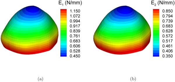
Reference distribution of the elastic parameters: (a) E1; (b) E2.
Kinematics and strain
We represent the strain invariants, such as J and λI , in tensorially covariant forms based on convected coordinates. In this representation, the surface is parameterized by surface coordinates ξα (α = 1, 2) in which a pair of coordinates P = (ξ1, ξ2) is regarded as the same material point during the deformation. We denote by X = X(P) and x = x(P) the position vectors of the material point P in the reference configuration I0 ∈ ℝ3 and a deformed configuration I ∈ ℝ3. The tangent vectors of the coordinate curves and form the basis of the surface tangent space at X(P) and x(P), respectively. The contravariant surface basis vectors {Gα, gα, α = 1, 2} are defined in the standard manner. The covariant reference and current metric tensors are Gαβ = Gα · Gβ and gαβ = gα · gβ , respectively. The contravariant components gαβ the metric tensors are such that , and similarly for Gαβ.
The surface deformation gradient, which maps the surface tangent vectors at X(P ) in I0 to the tangent vectors at x(P) in I, is
| (11) |
The Green-Cauchy deformation tensor is
| (12) |
In this curvilinear setting the aforementioned strain invariants are defined as
| (13) |
where g and G are respectively the determinants of the matrices [gαβ ] and [Gαβ ]. The fiber directions NI are assumed known in the reference configuration, and written as where NI are the components relative to the local surface bases. The current fiber directions are inferred from the mapping
| (14) |
In the convected coordinate system, , namely, the components remain the same. Thus, the fiber directions in all other configurations are trivially determined if their components in a configuration are specified. Note that nI is no longer a unit vector but encoded the fiber stretch. The square stretch is , which proves the formula (13)2.
Finite element strain computation
From the nodal coordinates in the reference and deformed configurations, strain distributions in each deformed configuration can be computed with the aid of the finite element interpolation. Here, the surface inside an element is parameterized by the finite element natural coordinates, which will be used as convected surface coordinates. From the finite element geometry, the base vectors in the deformed configuration and reference configuration are computed at each Gauss point by
| (15) |
where ΦI are element interpolation functions and N el is the total number of nodes per element. The left superscript indicates the load state. The metric tensors in the reference configuration and deformed configuration are computed by
| (16) |
The strain invariants in Equation (13) are computed accordingly.
Cauchy stress
The wall tension t is the resultant of the Cauchy stress σ:
| (17) |
here h is the current thickness of the membrane. In the convected coordinate system, the tension follows the Doyle-Ericksen formula [38]. Specializing to the energy function (3), we find
| (18) |
Again, the tension is a stress resultant having the dimension of force per unit length. Hereafter, the tension is called the wall stress or simply stress, without making the distinction.
3.2 Inverse stress analysis
Thirty-one deformed configurations were generated by applying pressures ranging from 50 to 200 mmHg at an interval of 5 mmHg. To simulate a typical inflation test, we assumed that the neck of the sac is clamped. The simulation of the inflation motion was conducted using the forward nonlinear membrane finite element in FEAP, a nonlinear finite element program originally developed at the University of California, Berkeley [39]. Figure 5 and 6 show the distribution of the principal stretches and principal stresses, respectively, at the deformed configuration under the highest pressure, p = 200mmHg. The largest principal surface stretch was λ1 = 1.085.
Figure 5.
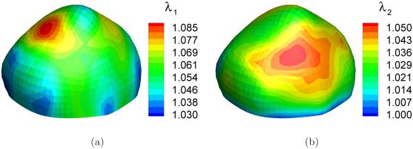
Distribution of the principal stretches in a deformed configuration (p=200 mmHg): (a) first principal stretch λ1; (b) second principal stretch λ2.
Following the inflation simulation of the cerebral aneurysm sac, we took each of the obtained deformed configurations as input, and applied the inverse method to compute the wall stress distribution. Cauchy stress was obtained at each Gauss point of the finite element mesh. A modified neo-Hookean constitutive model along with assumed model parameters was used to compute the wall stress. The strain energy function takes the form
| (19) |
where I1 = tr C = gαβ Gαβ . Similar to the elastic parameters Ei, the parameters ν1 and ν2 here are also effective elastic parameters which are multiplications of 3D elasticity constants with the wall thickness. ν1 = ν2 = 5.0 N/mm were used in the inverse FE analysis. To evaluate the insensitivity of of stress prediction to the assumed model, the stress distributions were computed with ν1 and ν2 increased by ten and a hundred times. The computed stress distributions were compared to the actual stress distribution computed from the forward FE analyses.
3.3 Parameters identification
The stress components are functions of the reference and current metric tensors, the fiber directions, and the elastic parameters appearing in the constitutive law. In each deformed configuration, we can obtain the stress components tαβ and the current metric tensor gαβ at each Gauss point. Here we assume that the stress-free configuration is known and, hence, the reference metric tensor components Gαβ are also known. The strain invariants can be computed according to Equation (13).
We denote the modeled stress in the i-th configuration by
| (20) |
Let be the “experimental” stress components obtained from the inverse analysis. The objective function is defined point-wisely, as
| (21) |
where N is the total number of deformed states. In tensor notation, If the global stress-free configuration is known, Φ is a function of the elastic parameters only.
Alternatively, as long as the modeled and experimental stress are described in the same convected coordinate system, one may construct the objective function as
| (22) |
where wi (i = 1, …, 3) are weights. One can judiciously choose the weights by observing different ratios among the stress components. The regression problem is formulated as
| (23) |
Here, l and u are the lower and upper bounds of the vector of regression variables [E1, E2, a, θ]T . The nonlinear regression was performed by a gradient-based, sequential quadratic programming (SQP) algorithm, SNOPT [40].
4 Results
4.1 Static determinacy and boundary layer
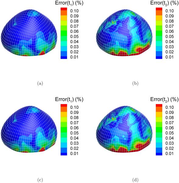
The static determinacy of this system can be demonstrated by comparing the stress solutions from the forward analysis (by the reference Holzapfel model) and those from the inverse analysis (by the auxiliary neo-Hookean model). Note that the two material models differ drastically in material symmetry and stiffness parameters. The principal stresses from the forward and the inverse solution are denoted by and respectively, i = 1, 2. We introduce a quantity to evaluate the difference. Figure 7 shows the distribution of ei in the highest pressure state (p = 200 mmHg). As can be seen from the figures, e1 and e2 are less than 1% in the most part of the sac. However, near the clamped boundary, especially for the second principal stress t2, the difference is relatively large. For example, e2 is larger than 10% near the boundary as indicated by red color (Figure 7(b)). Over four layers of elements above the boundary, the difference decreases to under 2%, indicating that the inverse solution approaches the static asymptote.
Figure 7.
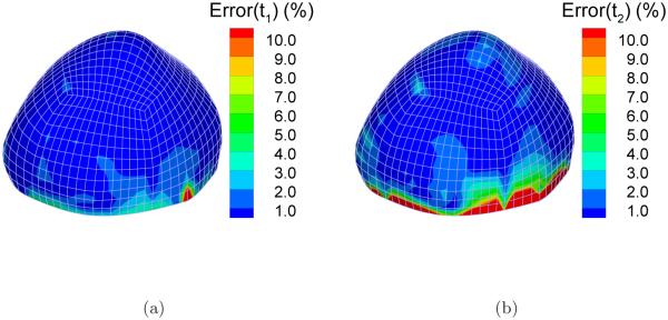
The absolute percentage difference between the principal stresses computed from inverse and forward FEA: (a) Error(t1); (b) Error(t2).
In real applications there is no leisure to compare the inverse solution to the “exact stress”, and for that reason, the boundary layer should be assessed differently. A practical way is to evaluate the sensitivity of stress to the auxiliary model (sensitivity test). The boundary layer may be identified as the region where the inverse stress solution changes relatively more under the change of material parameters. In essence, we are using material insensitivity to gauge static determinacy; the former is a necessary condition for the latter. In this study, the material parameters ν1 and ν2 were both increased to ten times and a hundred times, respectively, i.e., ν1 = ν2=50 N/mm and ν1 = ν2=500 N/mm. The percentage change in the principal stresses relative to that of the baseline neo-Hookean model is shown in Figure 8. In overall, the difference is very small, less than 0.05% in most part of the sac. Near the boundary, however, the difference is elevated. The maximum difference for t1 and t2 is 0.4% and 0.45% respectively, occurring near the boundary. There is approximately ten-fold reduction in the stress difference over the four layers of elements. The pattern is consistent with the stress difference between the forward and inverse analysis. Based on this observation, the four layers of elements were considered as the boundary layer where the inverse stress solution was deemed inaccurate. This region was excluded in parameter identification.
Figure 8.
The percentage difference between the principal stresses computed from inverse FEA with the baseline neo-Hookean model and elevated material parameters. Left column: first principal stress; Right column: second principal stress; Top row: increasing the values of the elastic parameters by ten times, i.e. ν1 = ν2 = 50 N/mm; Bottom row: increasing the values of the elastic parameters by a hundred times, i.e. ν1 = ν2 = 500 N/mm.
4.2 Distribution of the identified elastic parameters
Parameter identification was conducted at all the Gauss points in the identification zone (the cap region excluding the boundary layer). Initially the objective function Φ in Eq. (21) was used for all points. If at a point the residual of Φ is relatively large, we switched to the objective function Ψ. The weights wi were chosen according to the ratios among the experimental stress components, i.e. and , so as to fairly consider the influence of all the stress components by scaling them to a similar order. After the parameters were identified at all Gauss points, they were projected to the nodes by a least-square algorithm.
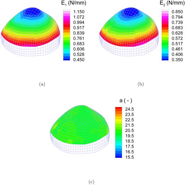
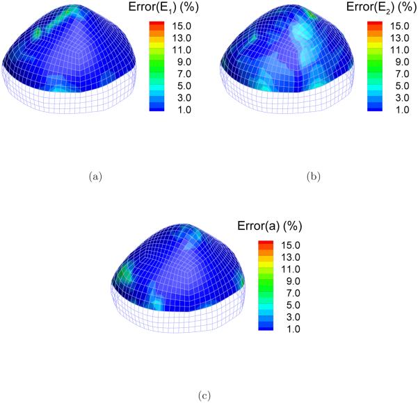
Figure 9 shows the distribution of the identified elastic parameters E1, E2, and a. Qualitatively judged from the distribution contour, the linear dependence of the identified E1 and E2 over the height was recovered. The homogeneous distribution of a was also identified successfully. The deviations from the reference value were computed at each node. Take Ei for example, the deviation was quantified by the relative error . Figure 10 shows the distribution of the relative errors in the identification zone. The errors are less than 1%, 2% and 1% for E1, E2 and a, respectively, in most part of the cap although there are several scattered spots of relatively higher errors.
Figure 9.
Distribution of the identified parameters: (a) E1; (b) E2; (c) a.
Figure 10.
Distribution of the identification errors of the elastic parameters: (a) Error(E1); (b) Error(E2); (c) Error(a).
By examining the distribution of the first principal stretch in Figure 5(a) and the distribution of the identification error of a in Figure 9(c), one may find that the identification accuracy correlates closely to the strain magnitude. The identification error of a is generally smaller in the region where the strain is larger. This is expected, because the nonlinear behavior is better exposed at a wider strain range.
The means, minimums and maximums of the identification errors over the identification zone are listed in Table 1. Notably, the mean errors for the three parameters are around 1%.
Table 1.
Means, minimums and maximums of the identification errors in the cap region of the aneurysm sac.
| Error(E1) | Error(E2) | Error(α) | |
|---|---|---|---|
| Mean (%) | 0.84 | 1.39 | 0.90 |
| Min (%) | 7.88 × 10⁻⁴ | 8.36 × 10⁻³ | 6.11 × 10⁻⁴ |
| Max (%) | 9.81 | 10.72 | 10.36 |
4.3 Predictability of the identified elastic parameters
Although the pointwise deviation in material parameters provides a direct gauge of the regression accuracy, this measure could be sometimes misleading because the optimization problem could have multiple solutions. In other words, seemingly different parameter sets may render equally good fit. Ultimately, it is the predictability of the identified model that matters. Based on this consideration, we evaluated the predictability of the identified elastic parameters by conducting two forward finite element simulations at a load state (p = 210 mmHg) which was not used in the regression. As discussed above, the boundary layer was excluded in the parameter identification. To facilitate the analysis, the material parameters in the boundary layer are assigned to the reference distribution in both analyses. Figure 11(a) shows the comparison between the predicted deformed configuration from the reference material and that from the identified one. Evidently, the two deformed configurations match extremely well. Figure 11(b) shows the node-wise percentage difference, defined as and d stand for, respectively, the nodal displacements computed from the reference and the identified material. The deviation is less than 0.2% in most part of the aneurysm sac. There are several nodes near the fundus where relatively larger deviation occurs, but the value is still low. The maximum difference is 0.6%.
Figure 11.
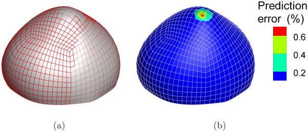
Predictability of the identified model: (a) Predicted deformed configurations from the reference material (solid surface) and the identified material (mesh) at 210 mmHg; (b) Percentage deviation in nodal displacement.
5 Discussion
We have proposed a pointwise approach for identifying the anisotropic heterogeneous material properties in cerebral aneurysms and tested the method numerically using simulated inflation tests. The tested aneurysm sac was imaged-based, and the material model incorporated the essential anisotropic and heterogeneous features. The stiffness parameters and material symmetry axes were assigned to vary continuously. To mimic real applications, the reference material was blinded to the inverse stress analysis. The boundary layer was identified using the sensitivity test, without invoking the reference material. The material parameters were identified and eventually the assigned distributions were successfully recovered.
The method possesses some noteworthy attributes:
The parameter regression is performed point-wisely at each individual point without coupling to others. This enables us to deal with, at least in theory, arbitrary property distributions. Remarkably, the size of the optimization problem depends only on the number of material parameters in the constitutive model, not the finite element mesh.
Since the stress-strain data are made available prior to identification, one has the opportunity to examine the stress-strain property and select an appropriate mathematical function, instead of assuming a constitutive form a priori. This is important in practical application, especially when no prior report of material behavior exists.
The stress analysis is decoupled from the parameter regression. Owing to this decoupled structure, it is possible to improve the stress solution or the regression algorithm individually without affecting the other. Since the nested iteration between stress analysis and optimization is avoided, the computational structure is much simpler and the computation cost can be significantly reduced.
The method is minimally destructive and has the potential to be extended to in vivo studies.
Altogether, the method can pointedly address some issues of the traditional global optimization approach for characterizing heterogeneous nonlinear materials.
The method has some limitations. First and foremost, since the method hinges critically on the property of static determinacy, it applies only to thin structures, primarily membranes and some thin shells. The method will not be appropriate if significant bending moments and transverse shear are needed to achieve equilibrium, as would happen to undulated surfaces. In this study, we utilized a convex sac. The surface was in fact slightly modified from the image geometry and a small concave region near the shoulder was removed. Nevertheless, we have recently considered a realistic aneurysm having concave regions [32]. We found that, despite the surface features, there are large portions of surface where the membrane response dominates (namely, the bending energy is order of magnitude smaller than the membrane energy). In such regions, the in-plane stress appears to remain statically determined. Based on this finding, we are optimistic that the method is applicable to some aneurysms with concave surface features. Of course, the method is not expected to work in high curvature regions such as ridges or folds. A possible strategy is to adapt a subdomain implementation whereby the smooth convex regions are isolated, and analyzed individually.
Another limitation, which relates critically to the potential in vivo extension, lies in the assumption on the stress-free configuration. While the assumption of known stress-free configuration is reasonable for in vitro experiments, it cannot be adapted in the in vivo setting because a cerebral aneurysm is eternally pressurized in its service life and, the stress-free configuration cannot be obtained from in vivo measurements. To characterize the elastic properties using in vivo pulsatile data, assuming available, one must identify, at least locally, the stress-free configuration. In [28], the present authors showed that the stress-free configuration can be represented locally by a metric tensor containing three parameters. In theory, the local metric may be identified together with the material parameters. This concept was tested numerically in the context of isotropic hyperelastic materials [28], including heterogeneous materials. However, the effectiveness in complex anisotropic models remains to be investigated. Research in this direction is underway in the authors’ group.
To a lesser degree of importance, the simulation embodied a number of constitutive assumptions that may not be realistic. First, we assumed that the material principal axis (the preferred direction) is everywhere parallel to the basal plane. This was purely an assumption and was introduced to facilitate analysis. If the fiber structure is characterized experimentally using techniques such as small angle light scattering [41, 42], such information can be incorporated into the model. Second, we assumed that the stiffness parameters decrease linearly over the height. Although the trend was motivated by an experimental report [1], the linear variation was again an assumption. It should be emphasized that the methodology does not depend on the assumed pattern of heterogeneity. The method, being a pointwise approach, should be readily applicable to other types of property distributions.
It is worth emphasizing that the inverse stress result needs user’s discretion. For thin structures the inverse method may yield non-unique solutions due to material instability and/or structural buckling. The method requires an auxiliary elasticity model; if the material model is chosen too soft, the inverse solution may fail to converge. Our experience suggests that stiffer models can help convergence and render the solution unique. But excessively stiff models will yield extremely small deformation and thus compromise the stress accuracy. Often a trial-and-error process is needed.
Finally, the stiffness parameters E1 and E2 contains the wall thickness. To delineate the intrinsic 3-D elasticity parameters, the local wall thickness must be measured. So far, there is no available technology to measure the aneurysm wall thickness in vivo.
In summary, this study highlighted the distinct features of the pointwise method and demonstrated the feasibility of identifying the anisotropic property distributions in cerebral aneurysms at the organ level. Undoubtedly, issues are expected to arise in real applications, for instance, the influence of surface measurement errors on the identification results. Currently, physical tests on biological tissues are being conducted by the authors. Although some limitations remain, we believe that the proposed method opens a new pathway for characterizing cerebral aneurysms and other thin biological organs. In the long term, the method may provide a framework for developing technologies for in vivo characterization of aneurysm tissues. Such a capability, once developed, will enable one to trace the property evolution during aneurysm growth. Information as such may shed light on understanding the natural history of a lesion.
Figure 6.
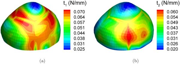
Distribution of the principal resultant stresses in a deformed configuration (p=200 mmHg): (a) first principal stress t1; (b) second principal stress t2.
Acknowledgements
The work was funded by the National Science Foundation grant CMS 03-48194 and the NIH(NHLBI) grant 1R01HL083475-01A2. The supports are gratefully acknowledged.
References
- [1].Seshaiyer P, Hsu FPK, Shah AD, Kyriacou SK, Humphrey JD. Multiaxial mechanical behavior of human saccular aneurysms. Computer methods in biomedical engineering. 2001;4:281–289. [Google Scholar]
- [2].Humphrey JD, Canham PB. Structure, mechanical properties, and mechanics of intracranial saccular aneurysms. Journal of Elasticity. 2000;61:49–81. [Google Scholar]
- [3].Crompton MR. Mechanism of growth and rupture in cerebral berry aneurysms. British Medical Journal. 1966;1:1138–1142. doi: 10.1136/bmj.1.5496.1138. [DOI] [PMC free article] [PubMed] [Google Scholar]
- [4].Kassel NF, Torner JC. Size of intracranial aneurysms. Neurosurgery. 1983;12:291–297. doi: 10.1227/00006123-198303000-00007. [DOI] [PubMed] [Google Scholar]
- [5].Ujiie H, Sato K, Onda H, Oikkawa A, Kagawa M, Atakakura K, Kobayashi N. Clinical analysis of incidentally discovered unruptured aneurysms. Stroke. 1993;24:1850–1856. doi: 10.1161/01.str.24.12.1850. [DOI] [PubMed] [Google Scholar]
- [6].Wiebers DO, Whisnant JP, Sundt TM, O’Fallon WM. The significance of unruptured intracranial saccular aneurysms. Journal of Neurosurgery. 1987;66:23–29. doi: 10.3171/jns.1987.66.1.0023. [DOI] [PubMed] [Google Scholar]
- [7].Wiebers DO, et al. Unruptured intracranial aneurysms risk of rupture and risks of surgical intervention. international study of unruptured intracranial aneurysms investigators. The New England Journal of Medicine. 1998;339:1725–1733. doi: 10.1056/NEJM199812103392401. [DOI] [PubMed] [Google Scholar]
- [8].Ujiie H, Tachibana H, Hiramatsu O, Hazel AL, Matsumoto T, Ogasawara Y, et al. Effects of size and shape (aspect ratio) on the hemodynamics of saccular aneurysms: a possible index for surgical treatment of intracranial aneurysms. Neuro-surgery. 1998;45:119–130. doi: 10.1097/00006123-199907000-00028. [DOI] [PubMed] [Google Scholar]
- [9].Ujiie H, Tamano Y, Sasaki K, Hori T. Is the aspect ratio a reliable index for predicting the rupture of a saccular aneurysm? Neurosurgery. 2001;48:495–503. doi: 10.1097/00006123-200103000-00007. [DOI] [PubMed] [Google Scholar]
- [10].Raghavan ML, Ma B, Harbaugh RE. Quantified aneurysm shape and rupture risk. Journal of Neurosurgery. 2005;102:355–362. doi: 10.3171/jns.2005.102.2.0355. [DOI] [PubMed] [Google Scholar]
- [11].Kyriacou SK, Humphrey JD. Influence of size, shape and properties on the mechanics of axisymmetric saccular aneurysms. Journal of Biomechanics. 1996;29:1015–1022. doi: 10.1016/0021-9290(96)00010-3. [DOI] [PubMed] [Google Scholar]
- [12].Shah AD, Harris JL, Kyriacou SK, Humphrey JD. Further roles of geometry and properties in the mechanics of saccular aneurysms. Computational Methods in Biomechanical and Biomedical Engineering. 1998;1:109–121. doi: 10.1080/01495739708936698. [DOI] [PubMed] [Google Scholar]
- [13].Ma B, Lu J, Harbaugh RE, Raghavan ML. Nonlinear anisotropic stress analysis of anatomically realistic cerebral aneurysms. ASME Journal of Biomedical Engineering. 2007;129:88–99. doi: 10.1115/1.2401187. [DOI] [PubMed] [Google Scholar]
- [14].Lu J, Zhou X, Raghavan ML. Inverse method of stress analysis for cerebral aneurysms. Biomechanics and Modeling in Mechanobiology. 2008;7:477–486. doi: 10.1007/s10237-007-0110-1. [DOI] [PubMed] [Google Scholar]
- [15].Canham PB, Finlay HM, Tong SY. Stereological analysis of the layered collagen of human intracranial aneurysms. Journal of Microscopy. 1996;183:170–180. doi: 10.1046/j.1365-2818.1996.840642.x. [DOI] [PubMed] [Google Scholar]
- [16].MacDonal DJ, Finlay HM, Canham PB. Directional wall strength in saccular brain aneurysms from polarized light microscopy. Annals of Biomedical Engineering. 2000;28:533–542. doi: 10.1114/1.292. [DOI] [PubMed] [Google Scholar]
- [17].Scott A, Ferguson GG, Roach MR. Comparison of the elastic properties of human intracranial arteries and aneurysms. Canadian Journal of Physiology and Pharmacology. 1972;50:328–332. doi: 10.1139/y72-049. [DOI] [PubMed] [Google Scholar]
- [18].Steiger HJ, Aaslid R, Keller S, Reulen HJ. Strength, elasticity and viscoelastic properties of cerebral aneurysms. Heart Vessels. 1989;5:41–46. doi: 10.1007/BF02058357. [DOI] [PubMed] [Google Scholar]
- [19].Toóth M, Náadasy GL, Nyaáry I, Kerényi T, Orosz M, Molnárka G, Monos E. Sterically inhomogeneous viscoelastic behavior of human saccular cerebral aneurysms. Journal Vascular Research. 1998;35:345–355. doi: 10.1159/000025604. [DOI] [PubMed] [Google Scholar]
- [20].Wineman A, Wilson D, Melvin JW. Material identification of soft tissue using membrane inflation. Journal of Biomechanics. 1979;12:841–850. doi: 10.1016/0021-9290(79)90169-6. [DOI] [PubMed] [Google Scholar]
- [21].Bylski DI, Kriewall TJ, Akkas N, Melvin JW. Mechanical behavior of fetal dura mater under large deformation biaxial tension. Journal of Biomechanics. 1986;19:19–26. doi: 10.1016/0021-9290(86)90105-3. [DOI] [PubMed] [Google Scholar]
- [22].Kriewall TJ, Akkas N, Bylski DI, Melvin JW. Mechanical behavior of fetal dura mater under large axisymmetric inflation. ASME Journal of Biomechanical Engineering. 1993;105:71–76. doi: 10.1115/1.3138388. [DOI] [PubMed] [Google Scholar]
- [23].Hsu FPK, Schwab C, Rigamonti D, Humphrey JD. Identification of response functions from axisymmetrical membrane inflation tests - implications for biomechanics. International Journal of Solids and Structures. 1994;31:3375–3386. [Google Scholar]
- [24].Hsu FPK, Liu ACM, Downs J, Rigamonti D, Humphrey JD. A triplane video-based experimental system for studying axisymmetrically inflated biomem-branes. IEEE Transactions on Biomedical Engineering. 1995;42:442–450. [Google Scholar]
- [25].Kyriacou SK, Shah AD, Humphrey JD. Inverse finite element characterization of nonlinear hyperelastic membranes. Journal of Applied Mechanics-Transactions of the ASME. 1997;64:257–262. [Google Scholar]
- [26].Seshaiyer P, Humphrey JD. A sub-domain inverse finite element characterization of hyperelastic membranes including soft tissues. Journal of Biomechanical Engineering-Transactions of the ASME. 2003;125:363–371. doi: 10.1115/1.1574333. [DOI] [PubMed] [Google Scholar]
- [27].Kroon M, Holzapfel GA. Estimation of the distribution of anisotropic, elastic properties and wall stresses of saccular cerebral aneurysms by inverse analysis. Proceedings of the Royal Society of London, Series A. 2008;464:807–825. [Google Scholar]
- [28].Lu J, Zhao X. Pointwise identification of elastic properties in nonlinear hyperelastic membranes. Part I: Theoretical and computational developments. Journal of Applied Mechanics. 2009;76:061013/1–061013/10. [Google Scholar]
- [29].Zhao X, Chen X, Lu J. Pointwise identification of elastic properties in non-linear hyperelastic membranes. Part II: Experimental validation. Journal of Applied Mechanics. 2009;76:061014/1–061014/8. [Google Scholar]
- [30].Kroon M, Holzapfel GA. A new constitutive model for multi-layered collagenous tissues. Journal of Biomechanics. 2008;41:2766–2771. doi: 10.1016/j.jbiomech.2008.05.033. [DOI] [PubMed] [Google Scholar]
- [31].Rossettos JN. Nonlinear membrane solutions for symmetrically loaded deep membranes of revolution. 1966. Technical Report NASA TN D-3297, NASA.
- [32].Zhou X, Raghavan ML, Lu J. Patient-specific wall stress analysis in cerebral aneurysms using inverse shell model. Annals of Biomedical Engineering. 2010;38:478–489. doi: 10.1007/s10439-009-9839-2. [DOI] [PMC free article] [PubMed] [Google Scholar]
- [33].Zhou X, Lu J. Inverse formulation for geometrically exact stress resultant shells. International Journal for Numerical Methods in Engineering. 2008;74:1278–1302. [Google Scholar]
- [34].Govindjee S, Mihalic PA. Computational methods for inverse finite elastostatics. Computer Methods in Applied Mechanics and Engineering. 1996;136:47–57. [Google Scholar]
- [35].Govindjee S, Mihalic PA. Computational methods for inverse deformations in quasi-incompressible finite elasticity. International Journal for Numerical Methods in Engineering. 1998;43:821–838. [Google Scholar]
- [36].Lu J, Zhou X, Raghavan ML. Inverse elastostatic stress analysis in predeformed biological structures: Demonstration using abdominal aortic aneurysm. Journal of Biomechanics. 2007;40:693–696. doi: 10.1016/j.jbiomech.2006.01.015. [DOI] [PubMed] [Google Scholar]
- [37].Lu J, Zhou X, Raghavan ML. Computational method of inverse elastostatics for anisotropic hyperelastic solids. International Journal for Numerical Methods in Engineering. 2007;69:1239–1261. [Google Scholar]
- [38].Doyle TC, Ericksen JL. Nonlinear elasticity. Advances in Applied Mechanics. 1956;4:53–115. [Google Scholar]
- [39].Taylor RL. FEAP User Manual: v7.5. 2003. Technical report, Department of Civil and Environmental Engineering, University of California, Berkeley.
- [40].Gill PE, Murray W, Saunders MA. SNOPT: An SQP algorithm for large-scale constrained optimization. SIAM Review. 2005;47:99–131. [Google Scholar]
- [41].Sacks MS, Smith DB, Hiester ED. A small angle light scattering device for planar connective tissue microstructural analysis. Annals of Biomedical Engineering. 1997;25:678–689. doi: 10.1007/BF02684845. [DOI] [PubMed] [Google Scholar]
- [42].Jimenez Hamann MC, Sacks MS, Malinin TI. Quantification of the collagen fibre architecture of human cranial dura mater. Journal of Anatomy. 1998;192:99–106. doi: 10.1046/j.1469-7580.1998.19210099.x. [DOI] [PMC free article] [PubMed] [Google Scholar]


