Abstract
A novel three degree-of-freedom microactuator based on thin-film lead-zirconate-titanate (PZT) is described with its detailed structural model. Its central rectangular-shaped mirror platform, also referred to as the stage, is actuated by four symmetric PZT bending legs such that each leg provides vertical translation for one corner of the stage. It has been developed to support real-time in vivo vertical cross-sectional imaging with a dual axes confocal endomicroscope for early cancer detection, having large displacements in three axes (z, θx, θy) and a relatively high bandwidth in the z-axis direction. Prototype microactuators closely meet the performance requirements for this application; in the out-of-plane (z-axis) direction, it has shown more than 177 μm of displacement and about 84 Hz of structural natural frequency, when two diagonal legs are actuated at 14V. With all four legs, another prototype of the same design with lighter stage mass has achieved more than 430 μm of out-of-plane displacement at 15V and about 200 Hz of bandwidth. The former design has shown approximately 6.4° and 2.9° of stage tilting about the x-axis and y-axis, respectively, at 14V. This paper also presents a modeling technique that uses experimental data to account for the effects of fabrication uncertainties in residual stress and structural dimensions. The presented model predicts the static motion of the stage within an average absolute error of 14.6 μm, which approaches the desired imaging resolution, 5 μm, and also reasonably anticipates the structural dynamic behavior of the stage. The refined model will support development of a future trajectory tracking controller for the system.
Keywords: piezoelectric actuator, multi-axis microactuator, microactuator modeling, PZT, endomicroscopy
1. Introduction
While engineering advances have enabled many break-throughs in the field of biomedical imaging, novel methods of endoscopic detection and diagnosis are still in great need. For example, to achieve accurate and early detection of cancer in the digestive tract, it is critical to develop a technique to rapidly visualize morphological changes in optically thick tissue in vivo [1]. In particular, it is useful to obtain vertical cross-sectional images of tissue, comparable to those that are typically used by pathologists for disease diagnosis. One novel optical imaging technique that can be used to achieve optical sectioning in high resolution for this task is dual axes confocal microscopy [1–5].
To develop an endomicroscopic system for the dual axes confocal architecture, an actuator that can move a lens or mirror surface in the tissue depth direction (axial or z-axis scanning) at a relatively fast speed is necessary. A large out-of- plane displacement of about 500 μm is needed to acquire greater biological details from the cells up to 500 μm below the inner surface of hollow organs [1]. A minimum bandwidth of 10 Hz in the out-of-plane direction is also required to avoid motion artifacts caused by heartbeats, organ peristalsis, and respiratory displacement [1]. In addition, a relatively large static tilt angle can be very useful in guiding tissue biopsy, and also for adjusting for optical misalignments in very small instruments. For endoscope compatibility, the actuator needs to have a footprint less than 5 mm in diameter.
Microelectromechanical systems (MEMS) technology has allowed for rapid development of scanning micro-mirrors for various optical applications. MEMS researchers have achieved very large rotational motion (>30°) about one [6–8] or two axes [9–10], but it is still challenging to produce large vertical translational actuation (>400μm), let alone with additional degrees of freedom. Additionally, many common MEMS transduction mechanisms have intrinsic limitations for the application of vertical cross-sectional imaging using a dual axes confocal endomicroscope. For example, electrostatic actuators have fast scanning speed and low power consumption, but usually their voltage requirement is high (>100 V), which is not desirable for an in vivo imaging device, even when producing small displacements (<100 μm) [6, 11]. Although electromagnetic actuators have produced 9° of angle or more, their out-of-plane displacements are small (<50μm) [12–14]. Electrothermal actuators can produce large displacements at a low voltage, e.g. 480 μm in the z-axis and 30° about the x and y axes at 8V as reported in [9], but their high power consumption (>100mW) increases the device temperature (>200°C), which can be undesirable in in vivo endoscopy [15]. Also, their relatively large thermal time constant limits scanning speed.
Piezoelectric actuators can overcome many of the aforementioned limitations of other types of actuators with their low voltage and power requirements, minimal heat dissipation, and large work density. Piezoelectric actuators with the desired degrees-of-freedom have been previously developed, but so far they have been intended for other types of endoscopic imaging and have consequently not targeted sufficiently large vertical translation for dual axes confocal microscopy, although they produced large angular displacements (~10° or even larger than 30°) [7–8, 17–18]. In addition, prior works on this class of piezoelectric actuator have only included limited mechanical modeling because either only individual actuation elements were analyzed for design purposes or the actuators have small degrees of freedom.
The three degree-of-freedom microactuator based on thin-film lead-zirconate-titanate (PZT) that is presented in this paper utilizes many of the advantages of piezoelectric materials to produce large enough vertical and angular displacements and high enough bandwidth to support early staging of cancer using a dual axes confocal endomicroscope. Compared to previous work [7–8, 17–18], PZT’s large work density was targeted primarily to generate large out-of-plane displacement by removing the substrate silicon underneath the PZT film using a fabrication process reported in [19].
Detailed evaluation of such an actuator’s mechanical model in this paper is important for understanding non-ideal outcomes after actuator fabrication. Using MEMS fabrication technology, it is very difficult to fabricate actuators such that they generate motions exactly as designed. As will be seen, motion is very sensitive to small perturbations in the dimensions of individual actuation elements in the actuators developed in this work, where large vertical displacement is aggressively sought. In other MEMS applications, robust controllers have been proposed, which are usually implemented on a simplified actuator model to regulate their motion [20–22]. While a robust controller with a simplified model is sufficient in some cases, there is a nearly direct trade-off between controller performance and the amount of uncertainty in the actuator model.
Modeling of a single beam within the actuation legs in this work has been reported before [23], while other similar multiaxis microactuators have to date been modeled using lumped parameter and finite element analysis (FEA) for design purposes [9–10, 16, 24]. However, a complete structural model for an actuator with folded leg design to describe large vertical (z-axis) and rotational (about x and y axes) motion including multi-axis coupling effects has not been developed. Furthermore, previously presented models have not accounted for fabrication uncertainties such as residual stress or dimensional variances of the structure. The combination of parameter variation with multiple leg operation will be seen to be important for understanding the actuators’ displacements.
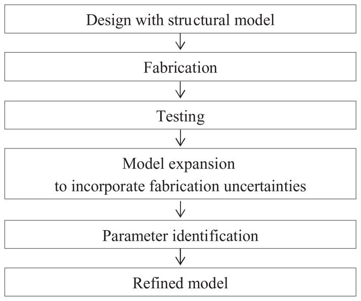
In this paper, in addition to the design and performance of the proposed actuator, a modeling technique that incorporates the effects of residual stress and dimensional variation of the structures from static motion measurements is introduced. The concept of this modeling technique can be also applied to other common types of MEMS actuators to obtain a more accurate analytic model. The approach to actuator design, testing, and model refinement is presented in figure 2.
Figure 2.
Schematic methodology for model development.
Among MEMS devices, the most similar prior study to this present model identification quantified the effects of unknown factors existing in fabricated pressure sensor test structures, where measurements of dynamic behavior of the system were used in conjunction with an FEA model to find effective system parameters [25].
2. Actuator design and static modeling
2.1. Actuator geometry and working principle
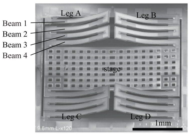
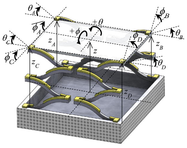
As shown in figure 1, the multi-axis actuator is designed to have a central scanning stage, on which a scanning mirror or lens may be incorporated. Each corner of the stage is supported by a leg, which consists of four symmetric PZT unimorphs connected in a serpentine pattern. Each four-unimorph leg produces out-of-plane motion and can be actuated independently from the other legs, which allows the stage to have motion in three directions. When all four legs or two diagonal legs are actuated, the stage moves vertically (z direction). When two adjacent legs are actuated, the stage tilts about the x-axis (θ direction) or about the y-axis (ϕ direction). Because thin-film piezoelectrics operate in contraction except for a small range of negative voltages and are sensitive to re-poling if voltage directions are reversed, tilting motion using differential voltages between pairs of legs is not generally advantageous.
Figure 1.
Scanning electron microscope image of a prototype scanning stage with notation labelled for beams and legs, where Beam 4 for each leg is the closest beam to the stage.
Showing one of the four unimorphs of a leg, figure 3 illustrates the working principle of the actuator. The active layer of the unimorph is made of thin-film PZT. In this design, where the unimorph beam is partially coated with gold, the contraction of the PZT film in its length direction is used to produce a vertical stroke when an electric field is applied across the PZT film. The presence of the additional gold layer shifts the neutral bending axis to above the mid-plane of the PZT layer, whereas without the gold layer the mid-plane of the PZT layer is below the neutral axis, causing the full beam to bend in an S-shape.
Figure 3.
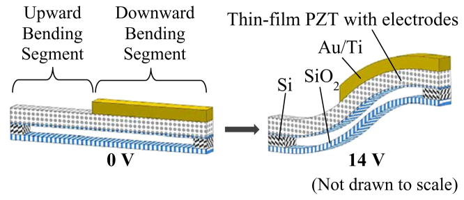
Schematic drawing of a beam, showing how two segments bend in different direction upon voltage application.
To increase the displacement, four symmetric beams are arranged in series, forming a folded-leg geometry. An even number of beams has been used to eliminate possible lateral shift (in the x-y plane) or bending (about the x-axis) of the stage in the existence of residual stress because some lateral motion is generated at the tip of each beam. The presence of the bottom SiO2 layer—the buried SiO2 layer of a silicon-on-insulator (SOI) wafer—in figure 3 is due to a limitation of the current fabrication process, where the silicon layer underneath the PZT is removed in the last step. However, this process allows the legs to have greater compliance and thus robustness during fabrication, compared to etching the buried SiO2 and silicon layers underneath the PZT by a backside etch before releasing the device.
2.2. Static modeling for design
In order to achieve the required performance of the actuator in the limited footprint available, design trade-offs were identified, initially through a static model of the stage described in this section.
2.2.1. Modeling of thin-film PZT unimorph
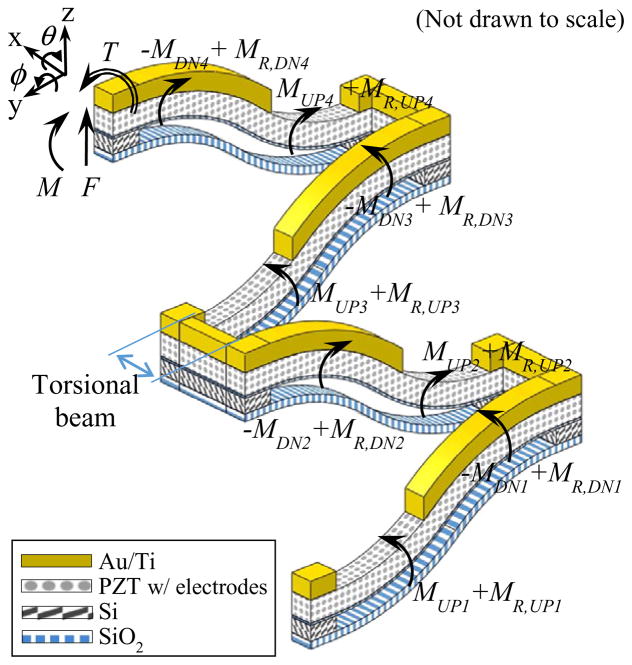
First, the deflection of Beam 1, the furthest beam from the stage in a given leg as labelled in figure 1, has been analyzed as shown in figure 4. The figure shows an external force (F), bending moment (M), and torsion (T) acting on the beam, which were assumed to have effect at its tip, as well as bending moments generated by PZT contraction (MUP, MDN) and residual stress (MR,UP, MR,DN) on each segment. Compressive residual stress is developed during the fabrication process as the films are sputtered or evaporated and the actuator undergoes different high temperature processes.
Figure 4.
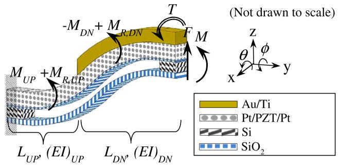
Free body diagram of a unimorph beam.
The actuation moment from the PZT film is generated as the force produced from the contraction of PZT does not act on the neutral bending axis of each segment of the beam. One way to approximate the PZT’s compressive stress is to use the effective electro-active piezoelectric strain coefficient (d31,eff), as follows [23]:
| (2.1) |
where and are nominal (short circuit) compliances; d33 and d31, piezoelectric coefficients; YPZT, the nominal elastic modulus; d31,eff, effective electro-active piezoelectric strain coefficient of the PZT; E3, the applied electric field. The effective electro-active piezoelectric strain coefficient is a function of voltage, and includes nonlinear phenomena such as electrostriction in addition to the combination of linear piezoelectric effects as written in equation (2.1). This expression for the PZT’s compressive stress can be used to find the actuation moment produced by the PZT film on each segment. The moment causes respective segments of the beam to bend upwards, and downwards, as described by the following equations.
| (2.2) |
| (2.3) |
where tPZT, APZT, z̄PZT are the thickness, cross-sectional area, and midline of the PZT layer, respectively. V is the applied voltage across the PZT layer (E3=V/tPZT), and z̄UP and z̄DN are the neutral axes of the respective composite segment.
Now the moment at a position y along the composite beam shown in figure 4 can be expressed as the sum of all the internal and external moments, with the zero reference for the y coordinate being the fixed end:
| (2.4) |
where LUP and LDN are the lengths of the portion of the beam without and with the additional gold layer, respectively. Meanwhile, the torsional displacement at the tip of the beam, ϕL, due to the torsion, T, at its tip can be expressed as follows:
| (2.5) |
where (GJ)comp is the beam’s torsional rigidity.
The moment expressions in equation (2.4) can be integrated and combined with equation (2.5) to obtain the twisting and tilting angle (or slope) and deflection of a single beam at the tip, given an initial tilting angle, ϕ0, slope, θ0, and beam deflection, z0 as follows:
| (2.6) |
In equation (2.6), S̃ext corresponds to a compliance matrix for the composite beam; S̃int, a force-mapping matrix relating the input voltage to the tip displacements; P̃, a geometric mapping accounting for the contribution of its boundary (initial) positions to the tip of the beam; R̃, mapping from residual stress to beam displacements. Each matrix is defined in Appendix A.
2.2.2. Modeling of PZT bending leg
Each leg consists of four bending beams connected by silicon links (also referred to as torsional beams) in a zigzag manner as shown in figure 5. When all external forces, torsions, and moments acting on a leg can be expressed as one effective force, torsion, and moment at its tip, one can calculate the effect of the external loading at the tip on each beam within the leg. It is assumed that the three silicon links between the unimorphs can be only twisted because of their high flexural rigidity (i.e. no bending due to a force or moment). Then, since the displacement of a single beam is expressed in terms of the contributions of external forces, piezoelectric force, boundary positions, and residual stress in equation (2.6), the displacement of a full leg can be obtained by summing the displacement of each beam. The residual moment on each segment is allowed to be different from one another because when the sample actuators were fabricated the deflection of each segment was observed to be different, despite the footprint of the actuator being small.
Figure 5.
Free body diagram of a leg.
Assuming perfect geometrical symmetry and homogeneous material properties among the four beams, the actuation moment terms become identical (i.e. MUP1 = MUP2 = MUP3 = MUP4, MDN1 = MDN2 = MDN3 = MDN4). By calculating the effects of the force, moment, and torsion at the tip of the leg on each beam and adding the displacements of all the beams together, the tip position of the leg can be written as follows:
| (2.7) |
where the superscript i denotes the leg number (i = A, B, C, D) and the subscript j the beam number (j = 1, 2, 3, 4), as defined in figure 1. This result is the compilation of four individual beams from equation (2.6), and similarly to equation (2.6), the tip position of the leg is expressed in terms of the applied external force, voltage, and each segment’s residual stress. Matrices in equation (2.7) are defined in Appendix B.
2.2.3. Modeling of stage motion
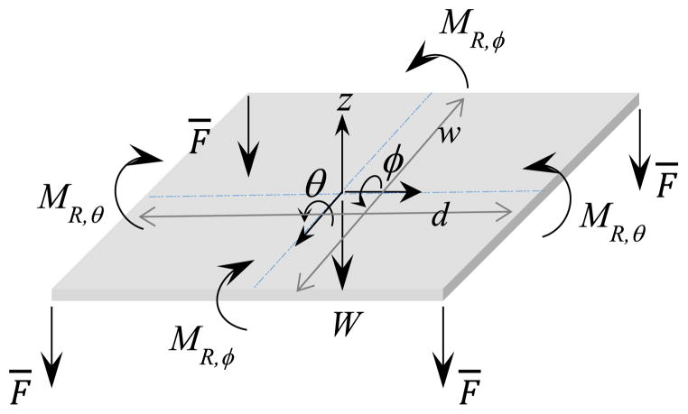
To describe overall stage motion now that the equation for leg displacements have been obtained, the forces and moments acting on the stage as well as reaction forces, moments, and torsions between the stage and each leg need to be identified. In figure 6, which shows the free body diagram of the stage, the reaction force, moment, and torsion for each leg are represented as a vector, (the subscript i = A, B, C, D indicates each leg), and the gravity force is denoted by W. In the figure, the directions of the reaction moment and torsion acting on each corner are the directions of the negative angles, opposite to the directions defined in figure 7, because the counterpart moment and torsion are defined to act on each leg in the positive angle directions. It is assumed that residual stresses on the stage only affect its initial deflections in two directions and that the effects of the residual stresses can be expressed using effective moments, M,R,θ and MR,ϕ. Then, the equation of motion for the stage can be written as the following.
Figure 6.
Free body diagram of the stage. (Not drawn to scale.)
Figure 7.
Schematic drawing of scanning stage showing the definition of positive angles and displacements of the center of the stage and the end of each leg. (Not drawn to scale.)
| (2.8) |
where
matrices describe how the torsion, moment, and force from each leg affect the stage motion.
Since the legs and the stage are connected, there exist physical constraints between the position of the stage and that of the tip of each leg such that:
| (2.9) |
As mentioned earlier, residual stresses on the stage also affect the legs’ initial displacements, and they are accounted for by the last two terms in equation (2.9). The matrices T2 and T3 relate the effective residual moments, M,R,θ and MR,ϕ, in the θ and ϕ directions, respectively, to the initial stage deflections (i.e. at 0V). The definitions of Ti (i=A, B, C, D), T2, matrices can be found in Appendix C.
Using the expressions for the leg position and physical constraints, i.e. equations (2.7) and (2.9), the reaction forces, moments, and torsions can be solved and written in terms of residual moments, piezoelectric forcing, and importantly the stage position. Next, they can be plugged into the stage’s equation of motion, i.e. equation (2.8), to describe the motion of the center of the stage. Then, the static position of the center of the stage is expressed in terms of the input voltage applied to each leg, effective residual moment, and gravity, as follows.
| (2.10) |
The derivations and matrices’ definitions are included in Appendix C. According to equation (2.10), the initial position of the stage is due to the gravity and residual stresses, and when voltage is applied to each leg its displacements are related to the stiffness of the structure and piezoelectric forcing.
2.3. Design trade-off analysis
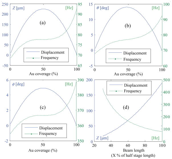
Design trade-offs between the displacements and natural frequencies of the stage have been studied as some key geometric parameters were varied. The first three plots, (a)–(c), in figure 8 show the influence of the ratio of the length of the downward bending segment to that of the upward bending segment on the displacement and natural frequency in each actuation mode when the total length of the beam is fixed. The results suggest that when 50% of the total beam length is overlaid with gold the displacements are at their maximum. When the coverage is below 50%, the longer the downward bending segment is, the more slope (θ) it produces at its tip, which makes the next beam produce a larger displacement. On the other hand, when the coverage is above 50%, the longer the downward bending segment is, the more it bends downward, ultimately decreasing the total displacement. As the gold coverage increases, it stiffens each beam, increasing the structural natural frequency of the stage. As expected, increase in the total length with a fixed ratio of segment lengths results in increase in the displacement and decrease in the natural frequency.
Figure 8.
Predicted displacement and frequency of the center of the stage at 14 V in Z direction, using only two legs, (a), in θ direction (b), in ϕ direction (c), as the Au coverage on each beam changes while its length is fixed; in Z direction (d) as the length of each beam changes when 70% of the total length of the beam is coated with Au.
Based on the results of this design trade-off study, prototype stage designs were chosen to maximize the beam length (i.e. half of the stage length) and to overlay 70% of the beam length in order to achieve a higher bandwidth than for the maximum displacement case, specifically 80 Hz of unloaded natural frequency for a bandwidth of 10 Hz when the stage carries a scanning mirror chip or an acrylic lens with a mass of 0.01g, such as Thorlabs’ APL0303-B, as a proof of concept payload.
3. Fabrication
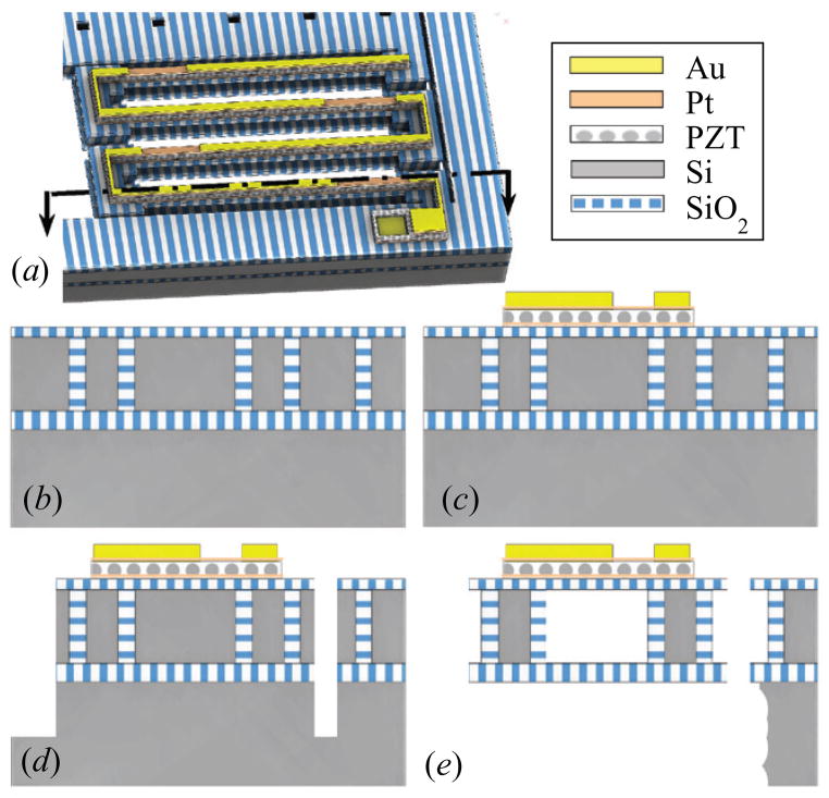
The prototype actuators were fabricated using a robust fabrication process where silicon structures are completely protected by a layer of SiO2 so that they can be preserved during the last releasing step of XeF2 etching as reported in [19]. As a summary of the process steps, narrow (3 μm wide) trenches defining the sidewalls of the silicon structures are firstly etched through the device layer of a SOI wafer (30 μm–2 μm–500 μm layer thicknesses) by deep reactive ion etching (DRIE). A series of deposition of SiO2 by low pressure chemical vapor deposition (LPCVD) and removal of SiO2 by chemical mechanical polishing (CMP) and reactive ion etching (RIE) is repeated to reduce the size of the keyholes formed in SiO2 trenches, while filling the trenches with SiO2. At the end of this step, CMP is used again to planarize the top SiO2 layer to use it as a base layer (0.5 μm) for PZT, as shown in figure 9 (b).
Figure 9.
Schematic fabrication steps shown in cross-sectional view of a bending beam as indicated in (a); planarized SiO2 layer over SiO2 filled trenches (b); deposited and patterned Au, PZT, and electrodes (c); top side DRIE and RIE (d); backside DRIE and XeF2 release (e).
To create a PZT and metal electrode stack, Ti/Pt (80nm) is firstly sputtered onto the SiO2 layer for the bottom electrode. A chemical solution process was used to deposit thin-film PZT (0.8 μm; Radiant Technologies, Inc.), and then Pt (0.1 μm) was sputtered. After the PZT stack is etched by ion milling and RIE, Au (1 μm) for the downward bending segment and bond pads is deposited by lift-off, as shown in figure 9 (c).
To both define the actuator structures and create release trenches, a sequence of DRIE, RIE, and DRIE is used to etch the device silicon layer, buried SiO2, and handle silicon layer, respectively, as illustrated in figure 9 (d). Then, the handle silicon layer underneath the actuator structures is etched from the backside of the wafer using DRIE. Lastly, XeF2 is used to isotropically etch silicon underneath the PZT stack to release the actuator, as represented in figure 9 (e). In this step, the silicon structures encapsulated in a layer of SiO2 are preserved, which allows a longer etching time to ensure complete release of PZT beams without etching support structures of silicon, and thus increases device yield, compared to an earlier process used [23]. As mentioned earlier, the removal of device layer silicon beneath the bottom electrode layer allows the unimorphs to achieve large bending deflections.
4. Actuator testing
After fabrication, prototype actuators were tested at different DC voltage levels, and their static and dynamic motion in response to various step voltage inputs was recorded. Applying step voltages from 14V to 2V in 3V-decrement and then from 2V to 14V in 3V-increment, the transient response of the center and four corners of the stage was measured. Before taking each measurement, the step input was applied about five times to allow the piezoelectric behavior of the PZT film to reach its steady state. This step was taken instead of a sustained poling process after observing the breakdown of PZT in other samples at the 15–20 V range. A Tenma’s DC Power supply (72–6905) was used to supply step voltages, and a Keyence displacement sensor (LK-G32) to measure the displacement. A sampling cycle of 20 μ sec and a built-in moving average filter were used to capture the transient motion of the stage, and they sufficed to measure the dynamics of the tilted stage. Although the peak time and damping ratio determined from the measurements are slower and higher, respectively, than the actual dynamics due to the implemented filter, it does not affect the measurements of the periods or the steady-state values, and the timing error due to averaging can be calculated. Different combinations of two legs were actuated at the same time to produce motion in each direction, as explained earlier.
Table 1 reports the maximum static displacement of one prototype actuator in each actuation mode at 14V, where static displacement was taken from the measurements of the transient response after it reached its steady state. It is noticed that angular displacement in the ϕ direction is smaller than in the θ direction, even though the opposite trend can be expected when the length of the stage is longer than the width if each leg only actuates its associated corner of the stage and provide the same actuation as other legs. However, it was observed that when legs A and B are actuated they also lift up the corners associated with legs C and D.
Table 1.
Static displacements of the stage at 14V.
| Actuation mode | Actuated legs | Displacement at 14V |
|---|---|---|
| translation in Z | A & D | 177.1 ± 4.9 μm |
| rotation about X (θ) | B & D | 6.4 ± 0.3 deg |
| rotation about Y (ϕ) | A & B | 2.9 ± 0.4 deg |
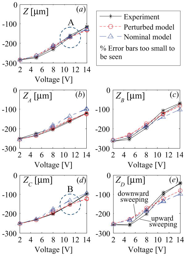
One experimental data set, out-of-plane actuation with legs A and D actuated, is plotted in figure 10 with the symbol * with deviation over typical 5 repeated tests. Although all the legs are designed to be symmetric and therefore to produce same displacements, they all show different displacements at each voltage. This is caused by non-identical initial deflections of the four legs at 0V due to non-uniform residual stress across the actuator and by different stroke lengths produced among the four legs.
Figure 10.
Static displacement results of the center (a), top left (b), top right (c), bottom left (d), bottom right (e) of the stage when legs A and D are actuated to achieve out-of-plane motion. (Z, ZA, ZB, ZC, ZD are defined in figure 1).
In a second experiment, an actuator with all four legs connected in parallel was driven to 15 V. Its total displacement was measured to be more than 430 μm, and the structural natural frequency to be approximately 200 Hz. This performance is very close to the required z-axis displacement for vertical cross-sectional imaging with a dual axes confocal endomicroscope, although multi-axis operation cannot be performed over the entire range of motion.
Residual stress can change due to environmental factors such as temperature or humidity, affecting the repeatability of the actuator performance. To improve the robustness of the actuator against environmental uncertainties, future work will include developing a closed-loop control strategy.
Device yield was primarily limited by poor adhesion of the gold layer to the piezoelectric legs and/or bond pads in spite of the use of an adhesion layer. In many cases, the delamination of the gold layers of the electrode pads were observed during wire bonding.
5. Development of refined model
5.1. Model perturbation
If modeling the micro-actuator as designed, assuming perfect symmetry and homogenous material properties across the whole device, then in equation (2.10), which describes the static motion of the stage, the stiffness matrix, Kn, becomes a diagonal matrix and Vcoef_n, the matrix mapping the input voltages to the piezoelectric forcing, has its elements such that each leg produces the same amount of forcing. If using this kind of ideal model, it is not possible to predict non-identical displacements of the four legs such as shown in figure 10, which is caused most likely by structural asymmetry among the four legs and non-homogenous material properties due to non-uniform residual stresses. With current limitations of MEMS fabrication techniques, however, realizing perfectly symmetrical and homogenous structures is very challenging. The reasons include photolithography mask misalignment and non-uniform etching and deposition. Thus, in an effort to predict experimentally observed behavior of the actuator more accurately, the actuator model developed in Section 2.2.3. was modified to account for the variations in the segment and stage dimensions and film thicknesses as illustrated in figures 11 and 12.
Figure 11.
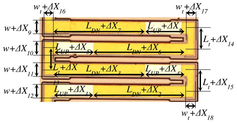
Optical microscope image of a leg with labels to show allowed dimensional variation.
Figure 12.
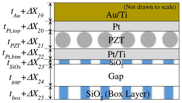
Schematic drawing of cross-section of unimorph to show allowed thickness variation, where Gap refers to the thickness of the silicon layer that was etched away.
In the perturbed model, the expression for the leg displacements, equation (2.7), can be rewritten as the following equation, which now represents that each leg has different compliance, piezoelectric forcing, and residual moment terms. The superscript i is used to denote each leg, and each matrix is defined in Appendix D.
| (5.1) |
When including the possible variation in the stage dimensions, equations (2.8) and (2.9) can also be rewritten in the same form as before but with slightly different coefficients. The equation of motion for the stage, equation (2.8), is modified as follows. The matrices are defined as same as those in equation (2.8) but with dimensional variations (i.e. d = d + Δd and w = w + Δw).
| (5.2) |
The physical constraints expression, equation (2.9), which relates the position of the center of the stage to that of each leg can be also rewritten as follows.
| (5.3) |
Now following the same steps as in Section 2—that is, calculating the reaction force, moment, and torsion for each leg and plugging them into the equation of motion for the stage—the expression for the dynamic motion of the center of the stage can be obtained, assuming it can be described as a standard 2nd–order mass–spring–damper system:
| (5.4) |
The damping is assumed to be decoupled, and the gravity and residual stress terms are combined into a constant forcing term. While equations (5.3) and (5.4) incorporate the effects of variations in residual stress and structural dimensions so that they might be able to describe the motion of the prototype actuator more accurately, this system is largely underdetermined.
The two matrix equations describing a three-degree-of-freedom system at 6 different voltage levels (0, 2, 5, 8, 11, 14V as experimentally applied) provide 18 equations. However, even when considering the static motion of the stage, there are a much larger number of unknowns: effective electroactive piezoelectric strain coefficient, d31,eff, at each voltage (5 unknowns); tilting angles of the stage at each voltage (12 unknowns); residual stress term associated with each leg (4 unknowns); variation in film thickness (28 unknowns per leg); variation in beam dimensions (18 unknowns per leg); variation in the stage dimensions (3 unknowns). From the experiments, only out-of-plane displacements of the stage (center and four corners) were measured at each voltage.
With knowledge about the physical system, especially fabrication tolerances, however, many of these unknowns can be bounded. For example, during the prototype fabrication sputtered or evaporated films were observed to have variations up to ±20% of the desired thickness. For the dimensional variations from lithography and etching processes, their bounds have been chosen to be up to ±5 μm. Many of the unknowns have their nominal (designed) values and their bounded minimum and maximum values as presented in table 2.
Table 2.
Nominal values of geometrical properties and their constraints and material properties.
| Property | Notation | Nominal Value (x) | Constraint on |Δx| |
|---|---|---|---|
| Film Thickness | |||
| Au+Ti layer | tAu | 1 μm | tAu × 0.2 |
| Top Pt layer | tPt,top | 0.105 μm | tPt,top × 0.2 |
| PZT layer | tPZT | 0.8 μm | tPZT × 0.2 |
| Bottom Pt+Ti layer | tPt,btm | 0.08 μm | tPt,btm × 0.2 |
| SiO2 layer | tSiO2 | 0.17 μm | tSiO2 × 0.2 |
| Buried SiO2 layer of SOI wafer | tBox | 2 μm | tBox × 0.2 |
| Elastic Modulus of Material [26–28] | |||
| Au+Ti | EAu/Ti | 86 GPa | – |
| Pt | EPt | 170Gpa | – |
| PZT | EPZT | 70 GPa | – |
| SiO2 | ESiO2 | 80 GPa | – |
| Si | ESi | 169GPa | – |
| Beam Property (L=Length) | |||
| Width of beam | w | 100 μm | 5 μm |
| L of segment w/o Au | LUP | 354 μm | 5 μm |
| L of segment w/Au | LDN | 823 μm | 5 μm |
| GJ of beam | (GJ)comp | 76.41μN · mm2 | – |
| Width of torsional beam | Wt | 80.5 μm | 5 μm |
| L of torsional beam | Lt | 170 μm | 5 μm |
| GJ of torsional beam | (GJ)t,comp | 36.95 mN ·mm2 | – |
| Stage Property (RI = rotational inertia) | |||
| Width of stage | wstg | 1024 μm | 5 μm |
| Length of stage | d | 2764 μm | 5 μm |
| Thickness of stage | tSi | 30 μm | tSi × 0.2 |
| Mass of stage | m | 0.162 μg | – |
| R. I. of stage (θ dir.) | Jθ | 105.7 mg· mm2 | – |
| R. I. of stage (φ dir.) | Jφ | 14.7 mg· mm2 | – |
5.2. Parameter fitting results
To begin identifying the refined model of a fabricated actuator, the terms related to the residual stresses and initial stage tilting angles can be obtained using the experimentally measured stage displacements at 0V. Then, using experimental static displacements at non-zero voltages and the expressions for the motion of the legs and stage, equations (5.3) and (5.4), one can estimate the value of d31,eff at each voltage, and can compute the static displacements (Z, ZA, ZB, ZC, ZD) at each voltage (2, 5, 8, 11, 14V) in each actuation mode (out-of-plane, tilting about x and y axes). The computed static displacements can be compared to experimentally measured displacements. Hence, this can be viewed as a bounded-input optimization problem written as follows.
| (5.5) |
This constrained nonlinear optimization problem was solved for the unknowns that can best predict the experimental static behavior of the stage in all three actuation modes simultaneously by sequential quadratic programming. As indicated in table 2, the material and mass properties were not varied. The mass properties were estimated using computer-aided design (CAD) software, and the product of shear modulus and polar moment of inertia, GJ, for each segment was obtained by finite element methods.
To see the effectiveness of modeling the variation, the optimization problem was also solved with different degrees of allowed variation, and the results are presented in table 3. In the table, no variation refers to when all the parameters are assumed to be as designed; beam-wise global, when all the beams are constrained to have same properties so that the unknowns for only one global beam are solved; leg-wise global, when all the legs are constrained to have same properties so that the unknowns for only one global leg are solved; local variation, when each beam has different properties.
Table 3.
Errors in μm between the measured and computed displacements as the number of possible parameter variation is increased.
| No Variation | Beam-wise Global | Leg-wise Global | Local Variation | ||
|---|---|---|---|---|---|
|
| |||||
| # of Variable Optimized | 0 | 14 | 45 | 171 | |
| Actuation Mode | Z | 16.75 | 16.75 | 16.75 | 12.34 |
| ϕ | 24.10 | 24.08 | 24.07 | 11.45 | |
| θ | 42.26 | 40.68 | 19.83 | 19.89 | |
| Total Average Error | 27.70 | 27.17 | 20.22 | 14.56 | |
As expected, the greater the number of the beams and legs that are allowed to have their own uncertainties, the more accurately the model captures the static motion of the prototype actuator. In the case where each leg is allowed to have its own variation, the reason why as many as 171 optimized variables were not able to produce a smaller error may be attributed to what the model does not account for such as non-uniform d31,eff coefficient across the device at a fixed voltage (as it can also vary as a function of strain), higher order piezoelectric effects (e.g. electrostriction), non-linear beam bending, and discrepancy in material properties (as deposition process can change mechanical properties of thin-film material).
For visual representation of the results, one set of the results has been plotted in figure 10 with the local variation referred to as a perturbed model and the no variation as a nominal model. Further analysis shows that the variation in the film thicknesses contributes to the asymmetry of the actuator more than the variation in the beam dimensions—that is, the model predicts better with looser bounds on the film thicknesses than with looser bounds on the beam dimensions. Hysteresis behavior of PZT was modeled by allowing the effective electro-active piezoelectric strain coefficient, d31,eff, to vary as a function of voltage, and the estimated d31,eff values are plotted in figure 13.
Figure 13.
Estimated effective electro-active piezoelectric strain coefficient, d31,eff, when all the parameters of the model are as designed (nominal) and are allowed to vary (perturbed).
With the identified parameters of the static model above, a dynamic model can be obtained by simply finding the damping term in equation (5.4). Assuming a decoupled damping, the damping coefficients that give good agreements with experimental measurements A and B in figure 10 were found by trial and error. Point A refers to the measurements taken at the center of the stage at 11V, and Point B to those at the bottom left corner of the stage at 11V. Table 4 shows some characteristics of filtered transient response of both experimental and simulation results. The moving average filter in the experimental system could reduce observed overshoot by up to about 10 %, and increase the measured peak time and settling time by about 3 msec and 6 msec, respectively. In the experiments, it is observed that the transient response of the legs includes different modes of vibration, resulting in a shorter period when averaged than the period of the response at the center of the stage. Only the first vibration mode was considered because it was fast enough to achieve the bandwidth needed for real-time imaging without any motion artifacts.
Table 4.
Transient Response.
| In figure 10 | Result | Avg period (ms) | Peak time(ms) | Over-shoot (%) | S.S.error (μm) | Settling Time, 5% (ms) | |
|---|---|---|---|---|---|---|---|
| Point A | Experiment
|
12.0 | 10.2 | 16.4 | – | 23.44 | |
| Sim | Perturbed | 12.8 | 10.8 | 16.4 | −0.5 | 17.98 | |
| Nominal | 10.4 | 9.9 | 15.2 | −4.03 | 16.38 | ||
| Point B | Experiment
|
11.2 | 13.0 | 12.8 | – | 43.1 | |
| Sim | Perturbed | 10.0 | 9.9 | 10.4 | 1.15 | 39.6 | |
| Nominal | 10.4 | 9.9 | 15.2 | −21.51 | 16.5 | ||
In general, the model accounting for parameter variation across the whole device captures the structural dynamic behavior of the center of the stage well, although it predicts the settling time to be faster than experimental results. In estimating the dynamic behavior of the legs, the perturbed model can represent the presence of other excited vibration modes better than the nominal model, although its averaged period is less accurate in comparison with the experimental result.
6. Conclusions
The design, fabrication, testing, and modeling of a thin-film piezoelectric micro-actuator with three degrees-of-freedom have been discussed. Its serial arrangement of thin-film PZT unimorphs bending in an S-shape allows the actuator to produce large out-of-plane displacement with high speed, which is challenging to achieve using MEMS actuators. A structural model has been developed based on classical beam theory to identify design trade-offs and to select designs such that certain performance specifications can be met. After fabrication using a robust encapsulated silicon-on-insulator wafer processing technique, prototype actuators have been characterized; their performance closely approaches that required for z-axis scanning in dual axes confocal endomicroscopy.
Based on the experimental static displacements of the stage at various voltages, a parameter fitting technique was applied to the structural model in order to identify the effects of variation in structural dimensions and residual stress developed during the fabrication process. A reasonable agreement between the experimental and modeling results, both statically and dynamically, showed the effectiveness of the presented system identification method, where a large number of unknown parameters were identified using only a limited number of available measurements. The modeling results also show that non-uniform residual stress and variation in structural dimensions present across the prototype actuator significantly affects the system behavior. By including their effects the model captured the experimental motion of the actuator more accurately. This modeling technique can be used for other flexure-based MEMS devices to refine model accuracy, which will allow for the use of more aggressive control schemes.
In future work, after obtaining static and dynamic models by the proposed method, actuators will be assembled into a prototype endomicroscope for imaging tests. To further improve trajectory-following accuracy during scanning, embedded sensing mechanisms will be used with the system model to implement feedback control, possibly with more detailed dynamic modeling of the specifically piezoelectric response through further material characterization.
Acknowledgments
This work was supported by NTH’s Bioengineering Research Partnerships R01 (CA142750) and Network for Translational Research U54 (CA136429). The authors thank J Martin and B Power at the US Army Research Laboratories; the staff and members of the Lurie Nanofabrication Facility at the University of Michigan; L Sanchez at Radiant Technologies, Inc. for their assistance in the fabrication of the prototype actuators.
Appendix A
Obtained using beam theory, equation (2.6) describes the displacements of a single beam in three direction. The S̃ matrices represent compliance for external and internal loading. P̃ and R̃ matrices map initial deflection and effective residual moments to the tip displacements, respectively.
In calculating the composite flexural rigidities, (EI)UP and (EI)DN, the buried SiO2 layer of a unimorph was treated as a spring in parallel with the PZT-Au stack.
Appendix B
Displacements of four beams are combined to describe that of a single leg (equation (2.7)), with Sext and Sext matrices defining beam compliance, I matrices the effects of initial deflections, and S matrices the directionality of the tip forces.
n=1 for legs A and D, n=2 for legs B and C.
L=LUP+LDN, Lt as defined in figure 11.
Appendix C
Equations (2.9) and (5.3) relate the position of the stage to that of each leg from physical constraints. Ti and matrices are used to map the position of the center of the stage to that of the end of each leg, and T2 and T3 to map the effective residual moments to initial stage bending.
n=1 for i=A and D, n=2 for i=B and C.
To obtain an equation of motion for the stage, equating equations (2.7) and (2.9) gives the following:
| (D.1) |
By inserting equation (D.1) into (2.8), (2.10) is obtained.
| (D.2) |
Appendix D
Similar to equation (2.7), equations (5.1) expresses the displacements of a single leg, but it describes a case where all the beams have different structural dimensions. Each matrix is defined as follows.
(i=A, B, C, D and j=1, 2, 3, 4)
n=1 for legs A and D, n=2 for legs B and C.
In order to find the stage’s equation of motion when the dimensions of each structural element is perturbed, first equation (5.2) can be rewritten as follows:
| (E.1) |
By equating equations (5.1) and (5.3),
| (E.2) |
By placing equation (E.2) into (E.1), (5.4) is obtained.
| (E.3) |
References
- 1.Mandella MJ, Wang TD. Handbook of Photonics for Biomedical Science. CRC Press; 2010. pp. 481–508. [Google Scholar]
- 2.Piyawattanametha W, et al. In vivo near-infrared dual-axis confocal microendoscopy in the human lower gastrointestinal tract. J Biomed Opt. 2012;17:021102. doi: 10.1117/1.JBO.17.2.021102. [DOI] [PMC free article] [PubMed] [Google Scholar]
- 3.Qiu Z, Liu Z, Duan X, Khondee S, Joshi B, Mandella MJ, Oldham K, Kurabayashi K, Wang TD. Targeted vertical cross-sectional imaging with handheld near-infrared dual axes confocal fluorescence endomicroscope. Biomed Opt Exp. 2013;4:322–30. doi: 10.1364/BOE.4.000322. [DOI] [PMC free article] [PubMed] [Google Scholar]
- 4.Qiu Z, et al. Vertical cross-sectional imaging of colonic dysplasia in vivo with multi-spectral dual axes confocal endomicroscopy. Gastroenterology. 2014;146:615–7. doi: 10.1053/j.gastro.2014.01.016. [DOI] [PMC free article] [PubMed] [Google Scholar]
- 5.Qiu Z, Rhee C-H, Choi J, Wang TD, Oldham KR. Large stroke vertical pzt microactuator with high-speed roational scanning. J Microelectromech Syst. 2014;23:256–8. doi: 10.1109/JMEMS.2014.2303643. [DOI] [PMC free article] [PubMed] [Google Scholar]
- 6.Milanovic V, Matus GA, McCormick DT. Gimbal–less monolithic silicon actuators for tip-tilt-piston micromirror applications. IEEE J Selected Top Quantum Electron. 2004;10:462–71. [Google Scholar]
- 7.Gilchrist KH, Dausch DE, Grego S. Electromechanical performance of piezoelectric scanning mirrors for medical endoscopy. Sensors and Actuators A:Phys. 2012;178:193–201. doi: 10.1016/j.sna.2012.02.029. [DOI] [PMC free article] [PubMed] [Google Scholar]
- 8.Naono T, Fujii T, Esashi M, Tanaka S. A large-scan-angle piezoelectric MEMS optical scanner actuated by a Nb-doped PZT thin film. J Micromech Microeng. 2014;24:015010. [Google Scholar]
- 9.Jia K, Pal S, Xie H. An electrothermal tip–tilt–piston micromirror based on folded dual s–shaped bimorphs. J Microelectromech Syst. 2009;18:1004–15. [Google Scholar]
- 10.Izhar U, Izhar AB, Tatic-Lucic S. A multi-axis electrothermal micromirror for a miniaturized OCT system. Sensors and Actuators A: Phys. 2011;167:152–61. [Google Scholar]
- 11.He S, Ben Mrad R, Chong J. Repulsive-force out-of-plane large stroke translation micro electrostatic actuator. J Micromech Microeng. 2011;21:075002. [Google Scholar]
- 12.Weber N, Hertkorn D, Zappe H, Seifert A. Polymer/Silicon Hard Magnetic Micromirrors. J Microelectromech Syst. 2012;21:1098–106. [Google Scholar]
- 13.Baba A, Okano H, Uetsuka H, Esashi M. IEEE 2003 2 axes optical switch with holding mechanism. Proc. IEEE Annl. Int. Conf. on MEMS; Kyoto, Japan. pp. 251–4. [Google Scholar]
- 14.Cho I-J, Yoon E. A low-voltage three-axis electromagnetically actuated micromirror for fine alignment among optical devices. J Micromech Microeng. 2009;19:085007. [Google Scholar]
- 15.Wu L, Xie H. A large vertical displacement electrothermal bimorph microactuator with very small lateral shift. Sensors and Actuators A: Physic. 2008;145–146:371–9. [Google Scholar]
- 16.Liu W, Zhu Y, Jia K, Liao W, Tang Y, Wang B, Xie H. A tip–tilt–piston micromirror with a double S-shaped unimorph piezoelectric actuator. Sensors and Actuators A: Physical. 2013;193:121–8. [Google Scholar]
- 17.Qian R, Wen Z, Chen L. A piezoelectrically actuated scaning micromirror integrated with angle sensors. Mems/Nems NanoTechnology. 2011;483:437–42. [Google Scholar]
- 18.Tani M, Akamatsu M, Yasuda Y, Toshiyoshi H, Ieee A two-axis piezoelectric tilting micromirror with a newly developed PZT-meandering actuator. Proc. 20th IEEE Int. Conf. on MEMS; Kobe, Japan. 2007. pp. 140–3. [Google Scholar]
- 19.Rhee C-H, Pulskamp JS, Polcawich RG, Oldham KR. Multi-Degree-of-Freedom Thin-Film PZT-Actuated Microrobotic Leg. J Microelectromech Syst. 2012;21:1492–503. [Google Scholar]
- 20.Yazdi N, Sane H, Kudrle TD, Mastrangelo CH. Robust sliding-mode control of electrostatic torsional micromirrors beyond the pull-in limit. Proc. IEEE 12th Int. Conf. on Solid State Sensors, Actuators and Microsystems; Boston, Jun. 2003; 2003. pp. 1450–3. [Google Scholar]
- 21.De Volder M, Coosemans J, Puers R, Reynaerts D. Characterization and control of a pneumatic microactuator with an integrated inductive position sensor. Sensors and Actuators A: Physical. 2008;141:192–200. [Google Scholar]
- 22.Choi SB, Kim HK, Lim SC, Kim JH. Position tracking control of an optical pick-up device using piezoceramic actuator. Proc. SPIE 3984; Newport Beach, CA. 2000. pp. 370–6. [Google Scholar]
- 23.Qiu Z, Pulskamp JS, Lin X, Rhee C-H, Wang T, Polcawich RG, Oldham K. Large displacement vertical translational actuator based on piezoelectric thin films. J Micromech Microeng. 2010;20:075016. doi: 10.1088/0960-1317/20/7/075016. [DOI] [PMC free article] [PubMed] [Google Scholar]
- 24.Tung YC, Kurabayashi K. A single-layer PDMS-on- silicon hybrid microactuator with multi-axis out-of-plane motion capabilities - Part I: Design and analysis. J Microelectromech Syst. 2005;14:548–57. [Google Scholar]
- 25.Ebert M, Naumann F, Gerbach R, Bagdahn J. Measurement of dynamic properties of MEMS and the possibilities of parameter identification by simulation. Proc. EuroSime: Int. Conf. on Thermal, Mechanical and Multi-Physics Simulation Experiments in Microelectronics and Micro-Systems; London. Apr. 2007; 2007. pp. 1–6. [Google Scholar]
- 26.Hopcroft MA, Nix WD, Kenny TW. What is the Young’s Modulus of Silicon? J Microelectromech Syst. 2010;19:229–38. [Google Scholar]
- 27.Sharpe WN, Pulskamp J, Gianola DS, Eberl C, Polcawich RG, Thompson RJ. Strain measurements of silicon dioxide microspecimens by digital imaging processing. Exp Mech. 2007;47:649–58. [Google Scholar]
- 28.Hemker KJ, Sharpe WN. Microscale characterization of mechanical properties. Annu Rev Mater Res. 2007;37:93–126. [Google Scholar]


