

Large biomolecules, such as peptides, proteins, antibodies, and nucleic acids are promising canditates for new therapeutics. These molecules can be too large, fragile, or insoluble for delivery by traditional routes of introduction; therefore, large volumes of these drugs are usually required to be effective, which significantly raises costs and can lead to harsh side effects. [1,2] Lower drug dosages would be preferred for treatment; however, the amount required often remains quite high in order to achieve a clinically-relevant therapeutic effect. In some cases, such as the treatment of cancer via antibody therapies, in spite of the high doses, as little as 1% of the administered therapy reaches solid tumors by standard systemic delivery alone. [3] While oral delivery of these new biologic therapies would be ideal, the harsh environment of the gastrointestinal tract and likelihood of first pass metabolism by the liver limit the selection of drugs delivered in this manner. [1] Hypodermic injection (including intravascular, intramuscular, etc.) enables the delivery of sensitive therapeutics, but they induce pain, provide opportunities for accidental needle sticks, and produce sharp, biohazardous waste. [1,4-7] Furthermore, in the case of vaccine delivery, hypodermic needles do not deliver doses to the optimum location to elicit an immune response; they penetrate into muscle, a region known to have a lower density of immunologically sensitive cells than skin. [1,8-11] Transdermal patches are effective for select time-released drugs (like nicotine and motion sickness medications), but the epidermis (specifically the stratum corneum) limits the diffusion of most drugs (>500 Da) through the skin. [4-7] Clearly, the ability to transport therapeutics effectively into the body remains a significant challenge.
While there are limitations to traditional transdermal drug delivery, which typically relies on the passive diffusion of therapeutics through the skin, this route of administration remains very promising. First, the gastrointestinal tract and first pass metabolism would be avoided by introducing the therapy transdermally. [4-7] In comparison to intravascular delivery, the peak plasma level of the drug is reduced, leading to decreased side effects. [6] Also, drugs with short biological half-lives or narrow therapeutic windows could be introduced effectively within the skin. [6] Finally, by introducing drugs transdermally, local exposure at the point to entry as well as systemic exposure through lymphatic drainage via Langerhans or dermal dendritic cells and diffusion into the blood system could be achieved. [5] While there are additional limitations to transdermal delivery, such as the difficulty of intradermal injection, dose consistency, sensitization, and unwanted enhancement of immunogenicity, we believe some technologies can be harnessed to overcome these obstacles. [4-6]
One recent attractive method to overcome the barrier of the skin employs microneedle patches, arrays of micrometer-sized projections for minimally-invasive drug delivery. Like hypodermic needles, these devices pierce the skin; however, their small size allows them to enter the skin without encountering any nerve endings, causing no pain. [1,7-10] Depending on their physical geometry, they can transport molecules of virtually any size to the dermal and epidermal layers, from small molecules to nano- and microparticles. [12] A dose sparing effect for the therapeutic itself has been observed compared to traditional transdermal patches. [8] The low complexity of microneedle devices may enable inexpensive fabrication and patient self-administration. Therefore, an optimized microneedle device could offer the efficacy of a hypodermic needle with the advantages of transdermal delivery.
Microneedles have been made from a wide variety of matrices and configurations; to date, most microneedles have been made from metals, silicon, or biodegradable and water-soluble polymers. [1,7-11,13] However, metal and silicon microneedles do result in sharp biohazardous waste after administration that has the potential to fragment in the body, posing immunogenic consequences. [7] Biodegradable and water soluble microneedles may be designed with the drug encapsulated in the needle matrix to be released during degradation or dissolution. One major advantage of these arrays is that sharp biohazardous waste would be avoided, eliminating potential immunogenicity and extensive disposal. [7-10]
Biodegradable microneedles are typically made by filling a mold with a matrix containing the drug of interest; generally, multiple vacuum and centrifugation steps are required to completely fill the molds, arduous steps that lead to lengthy fabrication times and pose issues to scale-up manufacturing. [1,8-11] A thick substrate, or backing layer, is attached to the array of microneedles to form a patch. After preparing microneedle patches, they generally are administered as shown in Figure 1A. Conventionally, the microneedle patch is applied topically to pierce the skin and penetrate into the viable epidermis or dermis depending on the physical dimensions of the needles. Due to skin’s elastic qualities, the entirety of the needle does not enter the skin. [14] The needles are left in the skin for the duration of the treatment period, from minutes to hours, and the substrate is then removed, extracting all parts of the needle that have not yet dissolved (usually 5–20% of each microneedle). [1,9-11] Consequently, a portion of the drug contained in the patch is removed, leading to a lower delivered dose than what was intended for the device.
Figure 1.
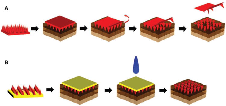
Schematics of the applications of traditional biodegradable microneedles and those made using PRINT. (A) The needles and substrate of one chemical composition (red) are inserted into the skin (top layer = epidermis, middle layer = dermis, bottom layer = subcutaneous fat). The backing is then removed. (B) The needles, of one chemical composition (red), and substrate, of a dissimilar chemical composition (yellow), are inserted into the skin. The backing is then dissolved with tap water.
To overcome the barriers in fabrication of microneedles seen previously, we have created microneedle arrays using the Particle Replication In Non-wetting Templates (PRINT) technique developed in our laboratory. [15] This technique combines a “top-down” method of soft lithography with traditional polymerization to create reproducible features on the nano- and micro-scale with precise control of size, shape, and chemical composition. [2,15-18] A wide range of materials including biodegradable and water-soluble polymers, sugars, and pure drug could be used, and the mild conditions required allow biologic cargo to maintain its function throughout the process. This technology allows for arrays to be made very quickly; after the desired mold is created, it can be used to make a microneedle patch in less than 5 min for batch processes. PRINT can be adapted on any scale of production; this particular advantage will allow for patches of virtually any size to be made affordably and quickly.
A schematic of a microneedle device made using PRINT can be seen in Figure 1B. Through this process, an array of discrete microneedles of the desired chemical composition would be manufactured and collected on a flexible, water-soluble substrate of a chemically dissimilar composition. In this way, the chemistry of the PRINT microneedles themselves will allow for the needles to carry payload and demonstrate rigid morphology, showing the desired tensile strength to overcome the skin, while the substrate’s matrix can be free of cargo and tuned for flexibility. Traditional microneedle arrays are often subject to the “bed of nails” effect, in which the force on each needle is distributed across the array, resulting in the inability of all needles to overcome the elasticity of the epidermis and pierce the skin. [14] The flexibility of the substrate allows the array of highly-dense microprojections to avoid this effect and break the stratum corneum more efficiently. [14] After application, the needle patch remains in the skin long enough to allow the polymer to dissolve or degrade, releasing its drug cargo. The substrate would then be dissolved, leaving the entire microneedle array in the skin. In this configuration, the entire payload of drug in the patch would be delivered. While this has been suggested, to our knowledge, no such patches have been created to date. Due to the versatility and reproducibility of the PRINT process, as well as the unique properties of the flexible, water-soluble substrate, we believe that these microneedle patches could be used to treat a wide range of local and systemic diseases, including vaccines, skin-invading cancers, psoriasis, and other conditions that require routine injections. In this study, we demonstrate the fabrication of 100% water-soluble microneedles on flexible substrates and their ability to deliver a drug surrogate (rhodamine B dye) to ex vivo murine and human skin specimens.
To manufacture PRINT microneedle patches, master templates were first prepared using a tilted-rotated photolithography approach adapted from Han et al. (see Supporting Information). [19-21] Briefly, a polished silicon wafer was coated with an anti-reflective layer; it was seen that this layer significantly reduced backside reflections and greatly increased the resolution of the resulting master templates (Figure S1, Supporting Information). A thick layer of negative photoresist (SU-8) was applied to the wafer via spin coating. Next, a mask with 200 × 200 μm squares and 200 μm spacing (base to base) was placed over the SU-8, and the complex was exposed to UV light at incidence angles of 18–25° (Figure S2). Both the mask dimensions and the incident angle of UV light determine the depth of the mold, and ultimately, the length of the microneedles. [19,22] The wafer was then rotated 90° about the surface normal and exposed again; a total of four exposures led to female master templates with square-pyramidal cavities. These templates were imaged via Environmental Scanning Electron Microscopy (ESEM) to determine the length and tip radii of curvature that would be achieved through replication. Seen in Figure 2A,B, the template used for this study was 360 μm in length and had tip radii of curvature under 10 μm. This length was selected based on the desire to reach the viable epidermis after piercing the stratum corneum.
Figure 2.
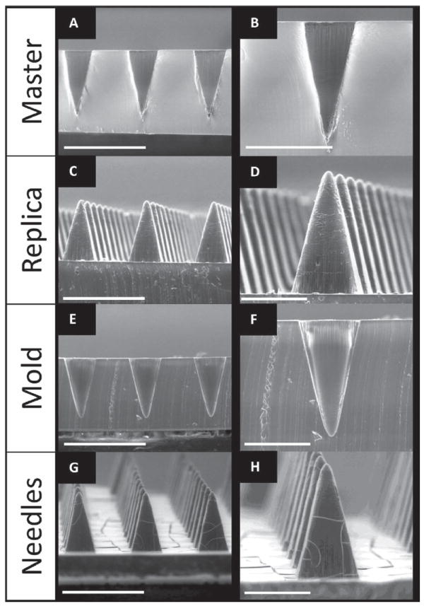
ESEM images of SU-8 Master template (A,B), PDMS template (C,D) and PFPE mold (E,F) and PVP microneedles (G,H) made from R2 SU-8 master (200 μm squares, 200 μm spacing). Needles show comparable lengths and tip diameters. Scale bars on A,C,E, and G are 500 μm. Scale bars for B,D,F, and H are 200 μm.
A positive replica of the master template was made as an intermediate. The replicas were fabricated using commercially available polydimethylsiloxane (PDMS) due to its low surface energy, ease of use, high flexibility, and low cost. [8] The replicas showed notable reproducibility of the master templates, having comparable needle lengths and tip radii of curvature via ESEM (Figure 2C,D). The positive replica was then used to make PRINT-compatible molds from a photocurable perfluoropolyether (PFPE) elastomer. PFPE is non-wetting and non-swelling, resulting in molds with a highly fluorinated surface that allow for microneedles of diverse chemical compositions to be made. [2,15-18] The elastomer was cast over the replica and cured under UV light to create molds for microneedle manufacturing. The PRINT molds are consistent with the dimensions of the replicas, reproducibly mimicking the SU-8 master templates (seen via ESEM, Figure 2E,F). It should be noted that, based on laboratory findings, each master template can be used to make hundreds of PDMS replicas, and each replica can be used to make at least 50 PFPE molds. Each PFPE mold can be used to create at least 10 microneedle arrays via PRINT processing.
The substrate for the microneedle backing was designed to be flexible and water-soluble. This is desirable for two reasons: 1) to facilitate improved penetration of the stratum corneum by avoiding the “bed of nails” effect, and 2) to create a microneedle patch that is 100% dissolvable to eliminate sharp, hazardous biowaste. [7,14] A matrix of Luvitec VA64, a polyvinylpyrrolidone/polyvinylacetate blend, was selected due to its high water solubility and biocompatibility for topical use. [23] Thick films of this polymer cast in methanol were not sufficiently flexible; therefore, multiple plasticizers were studied to lower the glass transition temperature (Tg) of the film to impart flexibility. In particular, triethyl citrate and trimethyl citrate in 1–3 wt% loadings showed promise for use as substrates; these films were analyzed by thermal gravimetric analysis (TGA) and differential scanning calorimetry (DSC). TGA studies were done to determine the 95% degradation temperature of the materials to avoid decomposition in the DSC. The DSC scans can be found as Figure S3. A glass transition temperature around 25 °C was seen for the triethyl citrate films with loadings of 1–3%; this Tg allowed for optimal flexibility and thermal stability at room temperature. Therefore, the blend of Luvitec VA64 in methanol and 2 wt% loading of triethyl citrate was selected for the fabrication of optimal substrates. Select substrates were loaded with 0.5 wt% fluorescein dye for imaging purposes.
Polymeric microneedles were then fabricated using the PRINT process (schematic shown in Figure S4). While PRINT can be applied to fabricate microneedles out of a wide variety of chemical compositions, polyvinylpyrrolidone (PVP) was selected as the first matrix for study. This polymer was chosen because it is highly water soluble, has a high tensile strength, and is a biocompatible FDA approved pharmaceutical excipient. [1] PVP with a molecular weight of 10 kDa was used because it has been shown that masses less than 20 kDa are cleared efficiently from the kidney after subcutaneous injection and, therefore, are safe for human use. [1] Rhodamine B dye at a loading of 0.1% was included in the matrix as a drug surrogate by mixing it into the PVP/water solution before film casting. Due to the non-wetting characteristic of the PFPE molds, excess PVP was wicked away after passage through a heated nip, leaving arrays of discrete microneedles that were harvested onto the flexible substrates. While heated fabrication was used to make PVP microneedles, PRINT is also compatible with photocurable systems, allowing for room temperature fabrication when needed for thermally-labile cargos. [15-18] For these studies, fabricated patches contained approximately 700 needles; however, the PRINT process is highly scalable for cost-effective manufacturing, enabling patches of virtually any size to be created affordably and quickly.
The microneedles were characterized by ESEM (Figure 2G,H) and macroscopic brightfield imaging (Figure 3). Microneedles demonstrated remarkable reproducibility (Figure 3A), with bases measuring 195.1 ± 4.4 μm, lengths of 361.4 ± 5.7 μm, and tip radii of curvature of 9.93 ± 1.7 μm (n = 15). These dimensions also closely mimic the master template, indicating that the microneedles retained their original shape and sharpness throughout processing. The flexibility of the array can be seen in Figure 3B,C. The rigid microneedles remained intact after the gentle bending of the array by hand. Both the microneedles and the substrate were seen to dissolve rapidly in the presence of a few drops of water; after 5 min, the device was completely dissolved. Therefore, novel 100% water-soluble microneedle patches on flexible substrates can be made quickly and reproducibly via PRINT processing.
Figure 3.
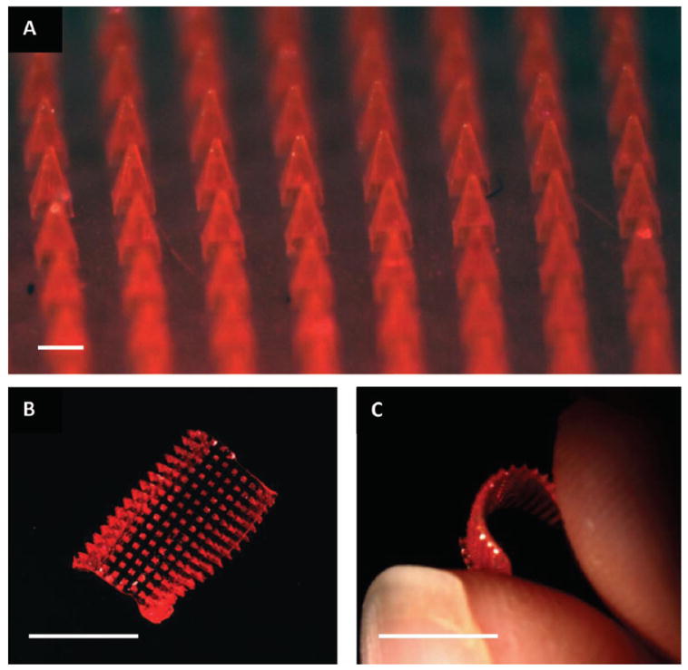
Brightfield macroscopic images of a microneedle patch. (A) The microneedle array morphology, showing reproducible needles. Scale bar is 200 μm. (B) A curled microneedle array, showing the flexibility of the array. Scale bar is 1 cm. (C) A side view of a curled microneedle array, showing the size of the array in comparison to human fingers. Scale bar is 1 cm.
Optimized PRINT microneedle arrays were tested in ex vivo murine skin samples. Flexible patches were “rolled” on and pressed into the skin with the gentle force of a thumb. Three different experimental conditions were compared: control (no microneedles applied), patches left in the skin for 10 s and then removed, and patches left in the skin for 10 min followed by the dissolution of the substrate with water.
Initial testing assessed the ability of the microneedles to successfully penetrate the stratum corneum of the murine skin samples. For this evaluation, all patches left were in the skin for 10 s, removed, and a green tissue marking dye was immediately applied to the skin and subsequently wiped off so that locations of skin penetration could be identified macroscopically. Figure 4A shows a greyscale image of a murine skin specimen after the application of microneedles for 10 s. The locations of epidermal breach can be seen on the skin; this was verified by histology. Additionally, the microneedles showed evidence of dissolution within the skin after 10 s. The drug surrogate could be visually perceived within sites of microneedle insertion and could not be wiped from the surface. Further brightfield macroscopic images of the patches after removal also showed at least half of the microneedle length had dissolved within this 10 s time period (Figure S5).
Figure 4.
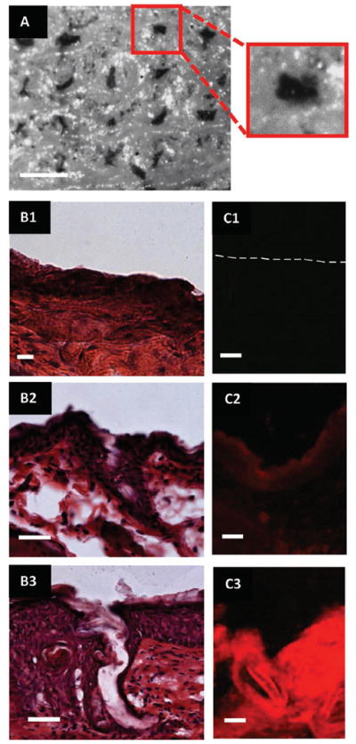
Images of ex vivo murine skin after testing with PRINT microneedles. (A) Brightfield macroscopic image after testing with microneedle patch for 10 seconds. The pattern of the microneedles can be seen on the skin. In the insert, a single piercing is highlighted. Scale bar is 400 μm. (B1–3) Brightfield microscopic images of skin sections after sectioning and histology (B1) Control skin. (B2) Skin after 10 second microneedle application. (B3) Skin after 10 minute microneedle application. Scale bar on all images is 35 μm. (C1–3) Fluorescent microscopy images of skin after sectioning. (C1) Control skin (dotted line outlines the upper epidermis of the skin). (C2) Skin after 10 second microneedle application. (C3) Skin after 10 minute microneedle application. Scale bar on all images is 35 μm.
After verifying that the microneedles could pierce the stratum corneum, further studies were conducted to evaluate the complete dissolution of the microneedle patches and release of the drug surrogate. For these studies, all patches were left in the skin for 10 min followed by the application of a few drops of water to the back of the microneedle patch. Within 5 min, the entire substrate (loaded with fluorescein) was dissolved (Figure S6) and the skin was wiped clean. No further dyes were applied. Rhodamine B was easily visible within the skin; the dye was not localized to the site of microneedle insertion but, rather, was present throughout the skin (Figure S7), suggesting that the drug surrogate was able to diffuse within the skin after 10 min.
The skin samples from all aforementioned experiments (including controls) were successively fixed, bisected in the z-direction (allowing for depth profiling), and cryosectioned for histology to confirm that the microneedles breached the murine stratum corneum and to evaluate the distribution of the drug surrogate. Half of the skin sections underwent hematoxalin and eosin (H&E) staining while half remained unstained to observe the rhodamine B fluorescence without the interference of eosin. After H&E staining and brightfield imaging, the control samples did not show any epidermal breach as expected (Figure 4B1); the skin was consistently smooth. Evidence of epidermal breach was seen in skin sections from both the 10 s and 10 min experiments, shown in Figure 4B2,3 by the breaking of the stratum corneum (the outer epidermal layer seen as dark purple). The penetration depths of the microneedles observed were consistently shorter than the lengths of the microneedles, but the insertion depth was longer for the 10 min tests. This is believed to be due to the elasticity of the skin and geometry of the needles themselves. [8,14] However, it is promising that the observed needle penetration depth increased when the patches were applied for 10 min, which more accurately reflects the ultimate intended clinical application of the 100% dissolvable patch.
Images of the unstained skin via fluorescent microscopy showed the efficiency of the drug surrogate delivery to the skin. Seen in Figure 4C1–3, a large qualitative difference in fluorescence intensity was observed among the three samples. While the control showed no fluorescence (Figure 4C1), an observable fluorescence was seen in the 10 s test in selective areas of the skin (Figure 4C2). Comparatively, considerably higher fluorescence intensity within the skin was seen for the 10 min time period throughout the whole skin section (Figure 4C3). This confirms that the drug surrogate was released from the needles and diffused beneath the stratum corneum throughout the duration of the patch application. The kinetics and mechanism of the drug surrogate will be probed in further in vivo experiments, but it is likely that the system can be optimized to deliver the full payload of the patches due to the nature of the flexible, water-soluble harvesting layer.
In addition to optimization and validation in murine skin samples, pilot studies to determine the ability of the PRINT microneedles to pierce human skin were also conducted. Human tissue excised from a patient with inflammatory breast cancer (IBC) was obtained from the Cooperative Human Tissue Network (CHTN). The conditions and procedures used for the murine tests were replicated on these tissue samples. Preliminary results indicate that epidermal breach and subsequent drug surrogate release are also seen when done on human skin specimens. Figure 5A,B shows a site of microneedle penetration and corresponding rhodamine fluorescence in IBC skin. As compared to the results obtained with the murine model, these results suggest that the drug surrogate release kinetics are slower in human skin than in murine skin, which was anticipated due to the increased thickness of human skin. While further optimization of the procedure and conditions will need to be done prior to clinical translation, these findings support the proof of concept that PRINT microneedles may be used to penetrate human skin and deliver loaded cargo.
Figure 5.
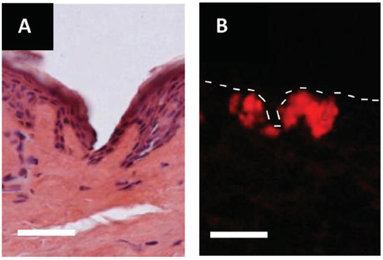
Microscopy images of skin penetration studies performed on ex vivo human skin from a patient with IBC. (A) Brightfield image of a skin after microneedle insertion for 10 s. (B) Fluorescence image after microneedle insertion for 10 min. The dotted line outlines the upper epidermis of the skin sample. Scale bar on all images is 70 μm.
Future studies are currently underway to assess the release and efficacy profiles of drug matrices loaded into the PRINT microneedles as well as the behavior of the devices under storage at various conditions to assess their robustness over time. Based on a survey of the literature, currently, microneedle research has focused on using these devices to administer vaccines and routine injections. Many vaccines are large, fragile biologics that could easily be incorporated into microneedle matrices for successful delivery through the skin. Vaccines for influenza and herpes simplex virus (HSP) have been incorporated into polymeric microneedles. [9,11] The group led by Dr. Mark Prausnitz has showed efficacy of microneedle vaccines in vivo; they showed in a mouse that a single dose of influenza vaccine with microneedles exhibited immune response superior to the same dose administered intramuscularly. [9] Separately, microneedles have been applied for conditions that require frequent injections, such as the administration of human growth hormone. [10]
In addition to these two fields, microneedles may also expand to treat many disease models that are currently unexplored, including skin and breast cancers. Specifically, microneedles for the treatment of IBC, the most aggressive form of invasive breast cancer known, could be advantageous. Unlike many breast cancers that are present as a lump, IBC dysplastic cells commonly reside in the dermal lymphatics, causing obstruction to lymphatic drainage and “inflamed” skin. [24] Much research on IBC treatment has focused on improving systemic therapies. In spite of these efforts, clinicians have recognized the complexity of IBC and have stated that prognosis of these patients remains poor. [24] As innovative strategies are critical, a novel transdermal-based approach could serve as an avenue for a local and possibly systemic, yet minimally invasive, therapy. Recently, nanoemulsions of tamoxifene citrate applied transdermally have been investigated for delivery for breast cancer treatment, showing the promise of transdermally applied therapeutics. [25] PRINT microneedles loaded with pertinent therapeutics could offer an attractive solution to improve the efficacy of existing IBC therapies while reducing the deleterious effects commonly associated with traditional injections.
Experimental Section
PDMS replica fabrication
Replicas of the SU-8 templates were made by casting a thick layer of silicone (Sylgard 184, Dow Corning) over the master. The PDMS was degassed in a vacuum desiccator for 2 h before centrifugation for 20 min at 3000 g and 4 °C; this process was then repeated once. The replica was left to cure under vacuum overnight at room temperature (RT) and was finished with a 2 h bake in a 65 °C oven. Templates were characterized by ESEM (FEI Quanta 200).
PFPE molds
Optimized PDMS templates were used to create PRINT molds using a perfluoropolyether-dimethacrylate (PFPE-dMA) elastomer with a molecular weight of 4 kDa (synthesis outlined in the Supporting Information). A 0.2 wt% solution of 2,2-diethoxyacetophenone (98%, Acros) in PFPE-dMA was drop cast onto the replica, and a flexible plastic sheet was applied to serve as a supportive backing. The mold was cured in a nitrogen-purged UV oven (λ = 365 nm), and the finished mold was separated from the replica for use. Molds were characterized by ESEM.
Substrate development
Flexible, water-soluble substrates served as the backing to the microneedle patches. Blends of a polyvinylpyrrolidone/polyvinylacetate copolymer (Luvitec VA64, BASF) and a variety of plasticizers were mixed in methanol at 30 wt% loadings, cast upon plastic sheets, and allowed to dry for 24 h at RT. Plasticizers studied included glycerol, castor oil, Tween80, PEG400, triethyl citrate, tributyl citrate, and trimethyl citrate at loadings of 1–10 wt%. Substrates plasticized with triethyl citrate and trimethyl citrate at loadings of 1–5% showed adequate flexibility and were subjected to TGA (PerkinElmer Pyris 1) and DSC (Q200, TA Instruments) analysis to determine the optimal blend. TGA decomposition experiments were done by heating 5–10 mg of substrate from 0–550 °C at 10 °C min−1, and the 95% decomposition temperature was determined; the upper temperature limit for the DSC experiments was to be no more than 50 °C lower than the 95% decomposition temperature for each material. DSC was used to determine the Tg’s of the substrates. Samples (5–10 mg) were crimped into aluminum pans and heated from −20 °C to 100–120 °C at a rate of 5 °C min−1, cooled at a rate of 10 °C min−1 to −20 °C, and heated again in a second cycle. Tg’s were determined from the second heating cycle. Results of these studies can be found in Table S1, Supporting Information. After analysis, triethyl citrate in 2% loading was selected as the optimal plasticizer for the flexible substrates in VA64. Select substrates were loaded with 0.5 wt% fluorescein (pure, Agros) for imaging by mixing the dye into the solution prior to casting.
Microneedle patch
Microneedles were fabricated using an adapted PRINT process (Figure S4).[1,13-15] PVP (10 kDa, Sigma Aldrich) films were loaded with 0.1% rhodamine B (99%, Agros) fluorescent dye and cast in water. A film (≈380 μm thick) was mated to the PFPE mold, covered with a plastic sheet, and passed through a heated nip at 105 °C, filling the mold. The complex was cooled to RT and the plastic sheet was removed. The filled mold was mated to the aforementioned flexible, water-soluble substrate, covered with a plastic sheet, and passed through a heated nip at 65 °C. The mold and plastic sheet were then removed, leaving a 100% water soluble microneedle patch. Microneedle patches were characterized with ESEM and brightfield macroscopy (Leica-Wild M420 Macroscope).
Skin penetration studies
Microneedle patches were tested on ex vivo nude murine skin (UNC Animal Core Facility) and human skin from a patient with IBC (CHTN) with the permission of the UNC Institutional Animal Care and Use Committee (IACUC). All skin samples were received and stored at −80 °C until testing occurred. Prior to experimental studies, the skin samples (in Eppendorf tubes) were thawed briefly in 37 °C tap water. The thawed samples were then pinned over corkboard and blotted dry to simulate in situ conditions. Flexible PRINT microneedle patches were then applied to skin for either 10 s or 10 min with gentle thumb pressure and then rolled with a hand roller. For the 10 s tests, pressure was applied for the duration of the test then the patch backing was removed. The site of the microneedle insertion was then exposed to green tissue-marking dye for 5 min. Commercially available green tissue-marking dye (Cancer Diagnostics) was prepared by diluting the solution in a 1:1 mixture with isopropanol. The dye was swabbed off with tap water. For the 10 min tests, the patch was rolled for 1 min and then left for 9 min at ambient conditions. The patch backing was then dissolved with a small aliquot (<200 μL) of tap water. All skin samples were then fixed for 2 h in 2% Paraformaldehyde (PFA) and left overnight in 15% sucrose in 1X PBS (Boston Bioproducts) at 4 °C. PFA was prepared by diluting a commercially available solution of 4% PFA (USB) in PBS with additional 1X PBS (Sigma) in a 1:1 mixture. Control samples of murine and human skin were also prepared; these samples were not exposed to microneedles but were fixed identically to the tested samples. Finally, the skin was imaged to identify microneedle insertion locations with brightfield macroscopy.
Analysis of skin penetration studies
Tested murine and human skin samples were then embedded in Tissue-Tec Optimum Cutting Temperature medium (Sakura Finetek), bisected in the z-direction, and cryosectioned (Leica Cryostat). Sections (12 μm) were taken at −25 °C based on manufacturer suggestions. Half of the sections were set aside for imaging using fluorescent microscopy (Olympus BX61 Upright Fluorescence Microscope). These sections were fixed briefly for 10s in FROZEN-FIX (Cancer Diagnostics) prior to coverslipping. The remaining sections were H&E stained (CRYO-KIT, Cancer Diagnostics) for brightfield microscopy imaging (Olympus BX61 Upright Brightfield Microscope). Staining was done using the procedure outlined by Cancer Diagnostics for the CRYO-KIT prior to coverslipping.
Supplementary Material
Acknowledgments
This work was supported by the NIH Pioneer Award and the University Cancer Research Fund at The University of North Carolina. We thank the Cooperative Human Tissue Network for providing fresh frozen tissue samples, as well as Charlene Santos and the Carolina Animal Core Facility for providing the murine skin samples. We would like to thank Liquidia Technologies, Inc. for support. PRINT is a registered trademark of Liquidia Technologies, Inc.
Footnotes
Supporting Information
Supporting Information is available from the Wiley Online Library or from the author.
Contributor Information
Katherine A. Moga, Department of Chemistry, University of North Carolina at Chapel Hill, CB #3290, Caudill Labs, Chapel Hill, NC 27599.
Dr. Lissett R. Bickford, Lineberger Comprehensive Cancer Center, University of North Carolina at Chapel Hill, Chapel Hill, NC 27599.
Dr. Robert D. Geil, Institute for Advanced Materials, NanoScience and Technology, University of North Carolina at Chapel Hill, Chapel Hill, NC 27599
Stuart S. Dunn, Department of Chemistry, University of North Carolina at Chapel Hill, CB #3290, Caudill Labs, Chapel Hill, NC 27599
Dr. Ashish A. Pandya, Lineberger Comprehensive Cancer Center, University of North Carolina at Chapel Hill, Chapel Hill, NC 27599
Dr. Yapei Wang, Lineberger Comprehensive Cancer Center, University of North Carolina at Chapel Hill, Chapel Hill, NC 27599
John H. Fain, Department of Chemistry, University of North Carolina at Chapel Hill, CB #3290, Caudill Labs, Chapel Hill, NC 27599
Christine F. Archuleta, Department of Chemistry, University of North Carolina at Chapel Hill, CB #3290, Caudill Labs, Chapel Hill, NC 27599
Dr. Adrian T. O’Neill, Lineberger Comprehensive Cancer Center, University of North Carolina at Chapel Hill, Chapel Hill, NC 27599
Prof. Joseph M. DeSimone, Email: desimone@unc.edu, Department of Chemistry, University of North Carolina at Chapel Hill, CB #3290, Caudill Labs, Chapel Hill, NC 27599; Lineberger Comprehensive Cancer Center, University of North Carolina at Chapel Hill, Chapel Hill, NC 27599; Institute for Advanced Materials, NanoScience and Technology, University of North Carolina at Chapel Hill, Chapel Hill, NC 27599; Department of Pharmacology, Eshelman School of Pharmacy, Carolina Center for Nanotechnology Excellence, Institute for Nanomedicine, University of North Carolina at Chapel Hill, Chapel Hill, NC 27599; Department of Chemical and Biomolecular Engineering, North Carolina State University, Raleigh, NC 27695; Sloan-Kettering Institute for Cancer Research, Memorial Sloan-Kettering Cancer Center, New York, New York, 10021.
References
- 1.Sullivan SP, Murthy N, Prausnitz MR. Adv Mater. 2008;20:933. doi: 10.1002/adma.200701205. [DOI] [PMC free article] [PubMed] [Google Scholar]
- 2.Enlow EM, Luft C, Napier ME, DeSimone JM. Nano Lett. 2011;11:808. doi: 10.1021/nl104117p. [DOI] [PMC free article] [PubMed] [Google Scholar]
- 3.Sedlacek H, Seemann G, Hoffmann D, Czech J, Lorenz P, Kolar C, Bosslet K. Antibodies as Carriers of Cytotoxicity. Karger; Würzburg: 1992. [Google Scholar]
- 4.Prausnitz MR, Langer R. Nature Biotechnology. 2008;26:1261. doi: 10.1038/nbt.1504. [DOI] [PMC free article] [PubMed] [Google Scholar]
- 5.Kim Y, Prausnitz MR. Drug Deliv and Transl Res. 2011;1:7. doi: 10.1007/s13346-010-0005-z. [DOI] [PMC free article] [PubMed] [Google Scholar]
- 6.Kumar R, Philip A. Trop J Phar Res. 2007;6:633. [Google Scholar]
- 7.Escobar-Chávez JJ, Bonilla-Martinez D, Villegas-Gonzalez MA, Molina-Trinidad E, Casas-Alancaster N, Revilla-Vasquez AL. J Clin Pharmacol. 2011;51:964. doi: 10.1177/0091270010378859. [DOI] [PubMed] [Google Scholar]
- 8.Lee JW, Park JH, Prausnitz MR. Biomaterials. 2008;29:2113. doi: 10.1016/j.biomaterials.2007.12.048. [DOI] [PMC free article] [PubMed] [Google Scholar]
- 9.Sullivan SP, Koutsonanos DG, del Pilar Martin M, Lee JW, Zarnitsyn V, Choi SO, Murthy N, Compans RW, Skountzou I, Prausnitz MR. Nat Med. 2010;16:915. doi: 10.1038/nm.2182. [DOI] [PMC free article] [PubMed] [Google Scholar]
- 10.Lee JW, Choi SO, Felner EI, Prausnitz MR. Small. 2011;7:531. doi: 10.1002/smll.201001091. [DOI] [PMC free article] [PubMed] [Google Scholar]
- 11.Raphael AP, Prow TW, Crichton ML, Chen X, Fernando GJ, Kendall MA. Small. 2010;6:1785. doi: 10.1002/smll.201000326. [DOI] [PubMed] [Google Scholar]
- 12.Coulman SA, Anstey A, Gateley C, Morrissey A, McLoughlin P, Allender C, Birchall JC. Int J Pharm. 2009;366:190. doi: 10.1016/j.ijpharm.2008.08.040. [DOI] [PubMed] [Google Scholar]
- 13.Martin CJ, Allender CJ, Brain KR, Morrissey A, Birchall JC. J Control Release. 2012;158:93. doi: 10.1016/j.jconrel.2011.10.024. [DOI] [PubMed] [Google Scholar]
- 14.Davis SP, Landis BJ, Adams ZH, Allen MG, Prausnitz MR. J Biomec. 2004;37:1155. doi: 10.1016/j.jbiomech.2003.12.010. [DOI] [PubMed] [Google Scholar]
- 15.Rolland JP, Maynor BW, Euliss LE, Exner AE, Denison GM, DeSimone JM. J Am Chem Soc. 2005;127:10096. doi: 10.1021/ja051977c. [DOI] [PubMed] [Google Scholar]
- 16.Merkel TJ, Jones SW, Herlihy KP, Kersey FR, Shields AR, Napier M, Luft JC, Wu H, Zamboni WC, Wang AZ, Bear JE, DeSimone JM. Proc Natl Acad Sci USA. 2011;108:586. doi: 10.1073/pnas.1010013108. [DOI] [PMC free article] [PubMed] [Google Scholar]
- 17.Canelas DA, Herlihy KP, DeSimone JM. Wiley Interdiscip Rev Nanomed Nanobiotechnol. 2009;1:391. doi: 10.1002/wnan.40. [DOI] [PMC free article] [PubMed] [Google Scholar]
- 18.Herlihy KP, Nunes J, DeSimone JM. Langmuir. 2008;24:8421. doi: 10.1021/la801250g. [DOI] [PubMed] [Google Scholar]
- 19.Han M, Lee W, Lee SK, Lee SS. Sensors and Actuators A: Physical. 2004;111:14. [Google Scholar]
- 20.Li B, Liu M, Chen Q. J Microlith Microfab Microsys. 2005;4:043008. [Google Scholar]
- 21.Kim JL, Allen MG, Yoon YK. J Microcech Microeng. 2011;21:035003. [Google Scholar]
- 22.Ami Y, Tachikawa H, Takano N, Miki N. J Micro/Nanolith. 2011;10:011503. [Google Scholar]
- 23.Fink JK. Handbook of Engineering and Specialty Thermoplastics. John Wiley & Sons; Hoboken: 2011. [Google Scholar]
- 24.Hurley J, Reis I, Silva O, Gomez C, DeZarraga F, Velez P, Welsh C, Powell J, Doliny P. Clinical Breast Cancer. 2005;5:447. doi: 10.3816/cbc.2005.n.003. [DOI] [PubMed] [Google Scholar]
- 25.Pathan IB, Setty CM. Intl J PharmTech Res. 2011;3:287. [Google Scholar]
Associated Data
This section collects any data citations, data availability statements, or supplementary materials included in this article.