1. Introduction
Neuroanatomical investigations typically require sectioning a perfused brain in serial or spaced serial sections, 20–50µm thick. This addresses the need for relatively thin sections, to allow for penetration of histological reagents and, at a later step, penetration of light during microscopic analysis. However, the sectioning process also creates problems, in particular, realignment or reconstruction of the tissue stacks in a 3-D space faithful to the whole brain configuration. The physical alignment problem becomes more severe as the field advances toward computational registration and reconstruction of individual sections, and algorithm based analysis/quantification of the experimental data. Frustratingly, obtaining precisely aligned sections, even at the first stage of tissue processing, is a difficult and error prone process (Figure 1).
Figure 1. Three-examples of Misalignment in the Coronal Plane.
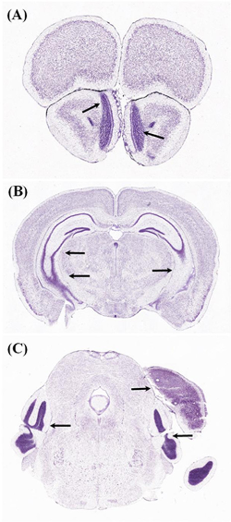
Obtaining whole brain sections, parallel to canonical planes of section, is an important but difficult goal in neurohistology. A–C, are three examples, from the widely used Allen Brain Atlas(Dong and Science, 2008), of A-P offset between the two hemispheres. This offset is due to tilting of the brain during cryostat positioning, which resulted in anterior shifting of the left hemisphere (and posterior shifting of the right hemisphere). This offset is indicated by black arrows, pointing to the olfactory bulb in A, hippocampus in B, and to the posterior cortices in C (left pointing arrows). The right pointing arrow in C, shows the posterior edge of the cortex (dorsal) and the hippocampus, which is present in the left-hemisphere, but missing from the right-hemisphere, at the same A-P level. Allen Reference Atlas, coronal level 27 is shown in (A); level 80 is shown in (B); and level 105 is shown in (C).
The problem is related to the lack of rigid edges on the brain that can be used for direct, standardized alignment to a fixed rectangular plane. For frozen sections, this problem is compounded by the opacity of the embedding medium that is often used to support the tissue, especially in cryostat sectioning. Because of this, the most common alignment methods rely on best-guess, operator based recursive adjustments, guided by the appearance of the blockface. For coronal and horizontal planes of sectioning, symmetry between the two hemispheres (i.e. equivalent anterior-posterior (AP) or dorso-ventral (DV) level) is a simple way to gauge accurate alignment but this is hard to judge qualitatively, even for the expert microtomist. The small coronal cross-sections at the anterior part of the brain, for example, offer only minimal criteria for gauging the appropriate medial-lateral and dorsal-ventral angles to achieve aligned sectioning of the two sides of the brain.
Recent approaches to address this problem have included the use of silicone molds (Leica, Model #39417501) that situate the brain in rectangular coordinates prior to freezing. Though effective at improving the accuracy of alignment, these molds present problems with tissue quality because of the increased thermal resistance of the silicone. They are also expensive. We have developed an alternative method to easily freeze rodent brains in standard stereotaxic coordinates. Our system allows for the casting of the brain shape directly into embedding medium (such as O.C.T). The system utilizes a 3-D printed model of a mouse brain to create a tailored cavity that effectively positions the brain in a standard rectangular base-mold. Once frozen, the embedded brain is sectioned relative to the fixed edge of the mold, which has been fabricated to correspond directly to one of the canonical planes of sectioning (coronal, horizontal, or sagittal). The size of the 3-D hemisphere model can be adjusted for age and species. We demonstrate the use of this technique for coronal and horizontal sectioning of the 56 day-old C57BL/6 mouse. This technique is easy to use and inexpensive (the per-mold cost is about 20× less than that of the silicone based system), and has been extensively used as part of the Mouse Brain Architecture project (http://brainarchitecture.org/mouse/about) to freeze over 1000 brains.
2. Materials and Methods
The method has several basic steps for simultaneously freezing and sectioning two mouse brains in stereotaxic coordinates. In the first step, prior to freezing the brains, two cavities are formed into a rectangular brain mold. The cavities are identical, and are orientated relative to the edges of the mold and to the standard anatomical planes. The cavities represent the shape of the left-hemisphere of a model brain and will contain the two brains in a sagittal orientation (i.e. left and right lateral surfaces will be in contact with the lower and upper cavities). A second, twin mold is than created, with cavities that represent the right-hemisphere. In the second step, one brain is placed into each cavity of the left-hemisphere mold. The right-hemisphere mold is then positioned above, and the joined molds are frozen into a single brain block. Third, after freezing, the resulting block is mounted on a cryostat and sectioned relative to one of the rectangular edges, which directly correspond to the canonical planes of sectioning for both brains.
For the sake of clarity, we provide the following short definitions:
Base-Mold: A rectangular mold that is used to contain and form the embedding medium during freezing.
Left or Right-Hemisphere Model: 3-D model of the left or right hemisphere, attached to a positioning bar, which is used to cast the hemisphere shape in the base-mold.
Cavity: The shape of the left or right hemisphere model that is cast into the left or right mold.
Cast Mold; Left or Right-Mold: A rectangular portion of frozen embedding medium that is shaped to the base-mold and contains two identical cavities.
Brain Block: The end result, after the two brains have been encased and frozen between the left and right molds.
2.1. System Components
In addition to the mouse brains, system components are (Fig. 2): two hemisphere models of the left-hemisphere; two hemisphere models of the right-hemisphere; one freezing platform, one base-mold; and embedding medium. All components were customized for this application, as detailed below.
Figure 2. Hemisphere Models and the Freezing Platform of the Pre-Cast Mold System.
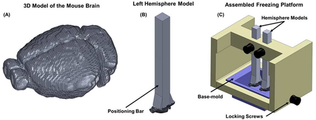
A 3D model of a 56-day old C57BL/6 mouse brain. The model was derived from the "two-sided" volumetric anatomical atlas of the left-hemisphere, which was computationally mirrored to create the right-hemisphere. The two hemispheres are shown combined, into a single digital brain, to illustrate the curvature of the brain, which is used to align it to the conical planes. A positioning bar was computationally added to each hemisphere model (B), to allow for a convenient means of holding, positioning, and aligning each model in the freezing platform, as shown in (C). The freezing platform is used to control the position of the two hemisphere models (left or right), relative to the base-mold, during freezing. The vertical position of the hemisphere models is adjustable, to allow for insertion and removal of the base-mold and the cast mold.
2.1.1. Animals
All animals were acquired from Jackson Laboratories (stock 000664). The animals were 56±3 day old mice, C5BL/6, with a weight of 18.8 – 26.4 grams. Avertine (2.5%) was used as the anesthetic. The animals were perfused with 4% paraformaldehyde (PFA) (JT Baker, #JTS898-7) through the heart, after a saline preflush of 50mL that was used to remove the blood from the circuit. The brains were extracted and post-fixed in a solution of 4% PFA with 10% sucrose (JT Baker, #4072-05) in PBS, for 24 hours. The brains were further cryo-protected in 20% sucrose in PBS for an additional 24 hours.
2.1.2. Hemisphere Models of the Brain
A physical model of the left and right hemispheres of a 56 day-old C57BL/6 mouse, with an attached positioning bar, was created using 3-D printing technology from a digital model (Fig. 2). The digital model of the left-hemisphere was derived from the "two-sided" volumetric anatomical atlas of the left-hemisphere, provided by the Allen Institute. To minimize complexity of the model (e.g., the number of physical surfaces), we sampled the atlas at 200µm. This volume contains integer-valued intensities at each volumetric pixel (voxel). This label-based atlas was binarized, such that volumetric pixels (pixel) outside the brain were assigned value 0 and voxels in any part of the brain were assigned value 1. The volume was then smoothed with a 3-D gaussian kernel and the outer boundary of the brain was extracted, forming a digital model of the brain that can be used for 3-D fabrication. This model was computationally mirrored, around the sagittal plane, to create a model of the right-hemisphere. To account for animal-to-animal variations, viscosity of the embedding medium and effects of paraformaldehyde perfusion, the size of each model was isotropically enlarged by 10%. The axis of the “two-sided” atlas were unchanged, which preserved the brain model in “flat skull orientation” and stereotaxic coordinates.
To each hemisphere model, a positioning bar, was computationally added. This rectangular bar (0.25 × 0.25 × 4.0 inches), is a convenient means of holding, positioning, and aligning each model in the freezing platform (see below). The bar extends from the medial plane and away from the hemisphere, with one edge corresponding to one canonical plane.
The two digital models (hemisphere models with attached bar), were 3-D printed in KryptonGreen, through Vistatek Corporation (Vadnais Heights, MN) at a resolution of 0.001" (25.4µm). KryptonGreen was chosen because the brain molds undergo significant stress when being removed from the frozen embedding medium and the higher tensile strength of the material increases durability and lifespan. Three-dimensional printing is ideally suited for this application, because the brain shape is structurally complex (e.g., consisting of many nonrectangular surfaces) and would be difficult to fabricate through conventional machining. Three-dimensional printing is also less expensive and allows for mass-production.
2.1.3. Freezing Platform
A custom platform secures the position of the hemisphere models, relative to the base-mold, during mold production. This platform is designed to suspend two hemisphere models, by the positioning bar, over the base-mold. The height of the hemisphere models is adjustable to facilitate extraction of the cast brain mold. A rendering of the platform is shown in Figure 2. The platform was 3-D printed in VeroWhite, through Vistatek Corporation (Vadnais Heights, MN) at the same resolution as the hemisphere models. VeroWhite was chosen because the platform is not load bearing and thus does not require to be fabricated in higher strength material.
2.1.4. Base-Molds
Customized base-molds are made by soldering a base plate to standard 1.5" square tubing (McMaster Corp). Importantly, sides and base should be at right angles. Brass was chosen because it is easily joined and facilitates optimal heat-transfer during freezing. Other base-molds, such as the Peel-A-Way (R-30) molds can be used; but since they are plastic, the rate of freezing is reduced and thermal damage to the brain is more likely. Commercial basemolds, such as the Tissue-Tek® Base-molds for Embedding Rings (Tissue-Tek, Model #4132), are not ideal because the sides are tapered (~5°). This angle means that the cavities cast in these molds will be offset by the taper angle.
2.1.5. Embedding medium
Embedding medium is used to create the two hemisphere molds and to support the brains in those molds during freezing. As in standard cryostat procedures, the embedding medium facilitates uniform freezing of the tissue, reduces damage to the edges of the tissue, and, after freezing, supports the tissue during sectioning. The present method can be used with any of the commercially available embedding mediums, such as O.C.T., however, we use Neg-50 (Richard Allen Scientific, Model #6502). We have found that the consistency of Neg-50 is closer to that of perfused tissue (after exposure to 24 hours of 10% and 20% sucrose). This helps to prevent the formation micro-cracks.
2.2. Mold Production and Brain Freezing
A 14-part illustration of the mold casting and brain freezing process is summarized in Figure 4. The freezing process is described for the production of molds with two cavities, intended to freeze two brains simultaneously. This method can be modified for freezing a single brain, by filling one of the unused cavities with embedding medium. The process is divided into two parts: Mold Production, which involves the use of the hemisphere models and the freezing platform to produce the left and right-molds, and Brain Freezing, which involves the use of the left and right molds to align and freeze the brains into a single block.
Figure 4. Freezing Process Workflow.

The freezing method, is a 14-step process, which results in a frozen block of embedding medium that contains two mouse brains, which are both aligned to the rigid edges of the block. Step 1, insert two hemisphere models (both corresponding to the left-hemisphere) and the base-mold into the freezing fixture. Step 2, adjust the vertical position of the hemisphere models. Step 3, add approximately 3ml of Neg-50 to the base-mold, to just barely cover the hemisphere models. Step 4, place the entire platform into a −80°C freezer for 15+ minutes. Step 5, return the platform to room-temperature (20–23°C) and allowed to acclimate for 10 minutes. Step 6, raise the hemisphere-models, to the highest point in the platform by the positioning bar. Step 7, use the side-to-side rolling motion to separate the base-mold and the cast-mold from the hemisphere models. This should result in an extracted cast-mold, with two cavities of the left-hemisphere. Step 8, repeat Steps 1–7, using hemisphere- models of the right-hemisphere. The cast molds should be stored at −80°C until brain freezing. Step 9, return the two cast molds (one of each hemisphere) to room-temperature, allow to acclimate 8–9 minutes, add fresh NEG-50 to both cavities and let stand for additional 1–2 minutes. Step 10, two brains are blotted with a paper towel, and carefully positioned into the left-mold. The lateral edge of each brain, should align with surface of the cavity. Step 11, place the right-mold over brains, and carefully align the brains in both molds. Step 12, place the resulting block into the base-mold. Step 13, freeze the brain block using dry-ice chilled isopentane. Step 14, extract the frozen brain block using a spatula. The brain block should be stored at −80°C, until sectioning.
2.2.1. Mold Production (Fig. 4, steps 1–8)
Step 1 is the insertion of two hemisphere models (both corresponding to the left-hemisphere) and the base-mold into the freezing platform. In step 2, the vertical position of the hemisphere models is adjusted, so that the lateral edge of the model is approximately 4.5mm from the bottom of the base-mold. In step 3, Neg-50 is added to the base-mold, to just barely cover the hemisphere models. Excessive amounts of Neg-50 will make the removal of the hemisphere models difficult, after the freezing, and should be avoided. Approximately 3mL of Neg-50 is needed. Air bubbles in the poured medium should be removed to ensure a homogenous solution. In step 4, the freezing platform is frozen in either a −80°C freezer for 15+ minutes or in dry-ice chilled isopentane.
Next, the cast molds are removed. The platform is returned to room-temperature (20–23°C) and allowed to acclimate through mild thawing for 10 minutes (Step 5). At the end of the acclimation, the surface temperature of the molds should be around −7°C (as measured with a standard thermocouple or similar device). The hemisphere models + cast mold + base-mold are then raised to the highest point in the platform by the positioning bar (Step 6). The base-mold is separated from the cast mold by carefully rolling it from side-to-side and slightly pulling. The same technique is repeated to separate the cast mold from the hemisphere models (Step 7). If the mold does not remove easily, wait an additional 1–2 minutes and try again. The same process (Steps 1–7) is repeated using models of the right-hemisphere (Step 8). Due to the nature of the freezing process, the top surface of the completed mold is typically uneven and rough, and should be smoothed by gentle abrasion with a metal file. An even block surface will facilitate even mating of the two molds during brain freezing. The cast molds are stored at −80°C until brain freezing.
2.2.2. Brain Freezing (Fig. 4, steps 9–14)
The two cast molds (one of each hemisphere) are removed from −80°C and allowed to acclimate for 8–9 minutes at RT (20–23°C). This results in a mold temperature of around −2°C. The surface temperature of the mold cavities is critical and must be above freezing. If the surface is too cold, once it is in contact with the brain, tissue will partially freeze, resulting in thermal damage. However, if the average temperature of the mold is too warm, the mold will slowly melt, degrading the shape. Once the proper temperature is reached, fresh Neg-50 is added to both cavities (Step 9) and allowed to stabilize for an additional 1–2 minutes. The resulting surface temperature of the cavities should be around 1°C, and the temperature of the embedding medium in the cavities should be around 5–6°C. At this temperature, the two brains can be safely placed into the cavities without causing thermal damage.
The two brains are then blotted with a paper towel to remove surface moisture, and carefully positioned into the left-mold. The lateral edge of each brain should align with the surface of the cavity. The brains are lightly pressed down and adjusted so that that the midline of the brain is aligned with the top surface of the mold (Step 10). It is convenient to note the identity of the two brains and their A-P orientation on the side of the mold, using a marker. In Step 11, the right-mold is placed over brains, and the brains are carefully aligned in both cavities. The two molds are lightly pressed together, and any excess embedding medium is removed from the sides of the block. The block should then be placed back into the base-mold (Step 12) and frozen using dry-ice chilled isopentane (Step13). The use of the base-mold helps to maintain the shape of the brain molds during freezing and facilitates heat-transfer. The ratio of isopentane to dry-ice can be adjusted so that the temperature of the solution is approximately −60°C. Under these conditions, the block is frozen in under 3 minutes. In the final step (14), the frozen block is removed from the base-mold using a spatula and stored at −80°C until sectioning.
2.3. Cryostat Mounting and Sectioning
Standard cryostat sectioning procedure(Beltz et al., 1997; Peters, 2009; Zeller, 2001) was modified to ensure that the sectioning was performed parallel to the surface of the block. The specimen and chamber temperatures were −13°C and − 16°C, respectively. After mounting the block on the chuck, recursive adjustments were made to the yaw (side-to-side rotation) and pitch (up-and-down rotation), until the knife appeared to be cutting equally from all sides of the block. These sections were entirely of Neg-50. Once the alignment was fixed, the block was sectioned further until the first indication of tissue appears, and then 20 µm serial sections of the entire block are collected using Tape-Transfer(Jiang et al., 2005; Salie et al., 2008). Sections can be collected using conventional techniques, but we find that the use of tape-transfer leads to better quality sections. Tape-transfer also makes it easier to maintain section identity and position on the slide. To evaluate the sectioning plane, irrespective of the possible distortion introduced during sectioning, blockface images were taken using a Nikon D300 camera (85mm f/3.5G).
2.4. Histology and Imaging
The sectioned material was allowed to dry overnight at 4°C and was then stained for Nissl bodies, using a thionin based protocol, and coverslipped using DPX. Imaging of the sections was performed using a NanoZoomer HT system, at a resolution of 0.5µm/pixel.
2.5. Pitfalls
To avoid thermal damage to the brain, careful attention needs to be paid to the operating temperatures. The critical juncture is when the brain makes contact with the frozen molds. The surface temperature of the molds must be >0°. Once encased in the left and right-hemisphere molds, the block should be frozen in dry-ice chilled isopentane within 3–4 minutes. If freezing takes longer (evident by the lack of homogenous white color in the Neg-50), additional dry-ice should be used to chill the isopentane. Thermal damage will manifest itself in the form of a “Swiss cheese” appearance on the stained histology sections. Direct temperature measurement is not needed each time, but a strict adherence to the noted acclimation times is strongly advised.
To maximize precise alignment, the midline of the brains should align parallel with the surface edge of the mold. Side-to-side rotation should be minimized. When positioning the right-mold, care should be taken not to disturb the brain from its placement. The attachment of the right-mold should be done slowly.
3. Results
Our main results are the quality of the sectioning, as judged by the final histological preparations. As shown in Figures 5 and 6, the resulting sections are of uniform and consistent high quality. Figure 5 illustrates the blockface (A,C), as it appears during cryostat cutting, with the two embedded brains. The good alignment of the two sides of the brain is illustrated at two A-P levels (Fig. 5B, 5D, solid arrows) for the top brain, and at one level (Fig. 5E) for the bottom brain. Note ease of comparison between the two brains (Figs. 5D and 5E); that is, the pre-cast preparation delivers a high degree of standardization. With close examination, a slight offset can be detected; for example, the right hippocampal formation is slightly larger (more posterior) relative to the left (dotted arrows in Fig. 5D). The offset is due to the smaller size of the brain, relative to the molds, which is needed to allow for proper setting of the brain during the pre-freezing step (see Discussion).
Figure 5. Coronal sections of two brains, processed using the Pre-Cast Mold System.
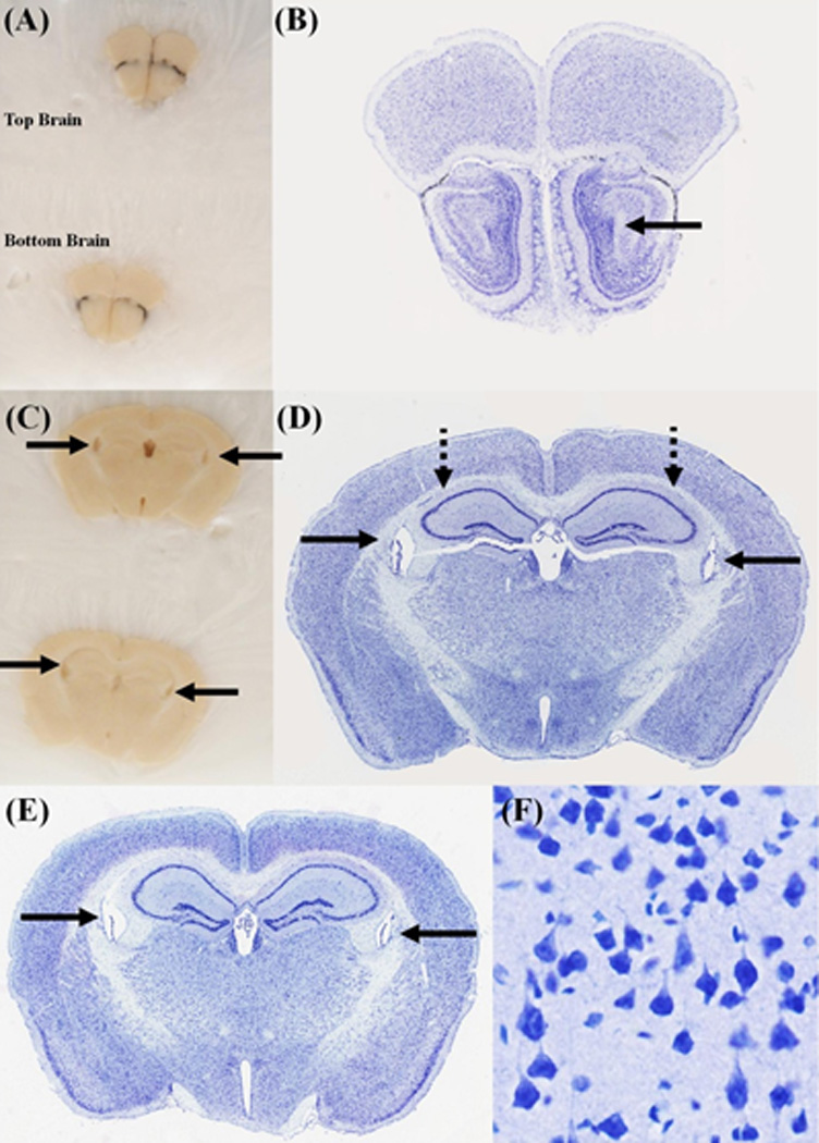
(A) and (C) Blockface images were taken at two coronal levels. The corresponding Nissl stained sections are shown in (B) and (D-F). The "top brain" is shown in (B) and (D). The bottom brain is shown in (E). The solid black arrows point to the lateral ventricles. The dotted black lines point to the Hippocampal formation (HPF). All sections appear symmetrical on the blockface, but a closer inspection of the stained sections, shows an offset of about 2–3 atlas plates. This is best seen in the lateral extent of the HPF. One of the advantages of this system, is that two brains can be frozen in the same block, and are cut at the same approximate level, as can be seen in (D) and (E). (F) A high-magnification view of the stained sections shows that the cellular morphology is well preserved.
Figure 6. A horizontal section, of a mouse brain, processed using the Pre-Cast Mold System.
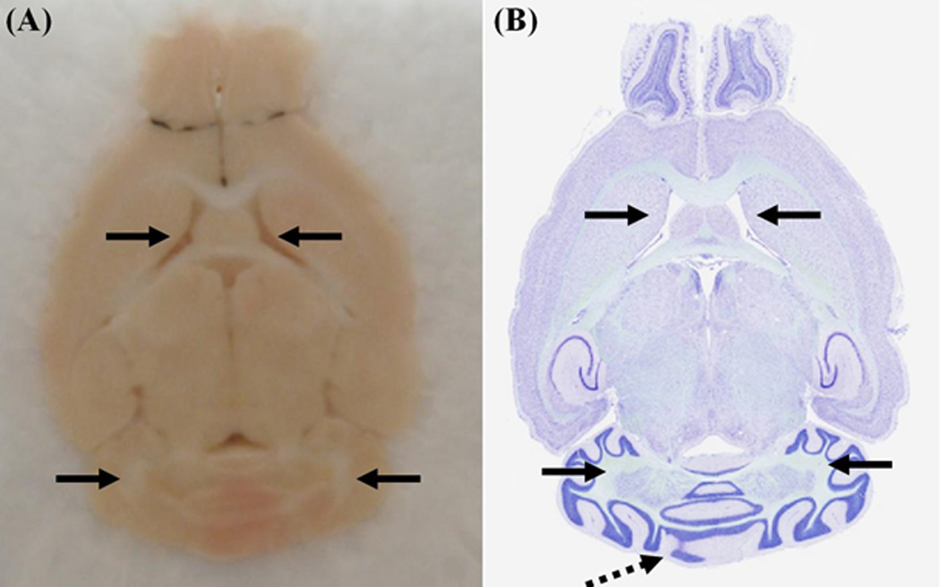
(A) Bockface image. The corresponding Nissl stained section is shown in (B). The black arrows point to the easily identifiable landmarks on the two images. The section appears symmetrical, but a offset of 1–2 atlas plates exists. This is seen in the medial cerebellum, as denoted by the dotted black arrow.
Figure For Reviewer, not intend to be included in the paper.
In addition to the excellent alignment, another positive feature is the good condition of the histology sections. These are relatively unblemished (i.e. no nicks or other cutting artifacts) and undistorted relative to the macro shape of the brain. At higher magnification (Fig. 5F), the cortical cells can be evaluated as structurally intact.
The main features – excellent alignment and tissue preservation – are shown for a horizontally sectioned brain in Figure 6. Solid arrows again point to bilaterally symmetrical representative features. The slight offset (now most evident in the dorsal/ventral plane) can be detected medially, at the cerebellum (dotted arrow).
4. Discussion
Aligning the brain in standard coronal, horizontal, or sagittal planes has long been recognized as a basic problem in the preparation of histological materials. One approach to this problem has been to “block” the postmortem, in situ brain in stereotactic coordinates. However, this procedure does not necessarily carry-over to a preserved alignment in the sectioning process. The challenge of a perfect alignment can be seen even in high quality, carefully prepared atlases; for example, the Allen Reference Atlas (Fig. 1). These challenges are even greater for applications where the end-goal is a 3-D reconstruction of the cut sections, because of the need to maintain a common sectioning plane across the entire brain. There is also a need to minimize loss of tissue, which can occur when the technician makes major or repeated minor adjustments to the sectioning plane.
Our method, as we have shown, allows simple, inexpensive, and reproducible accuracy of alignment. The key element of the system is the encasement of the brains in a size and shape specific cavity, which is preformed relative to the rectangular edges of the base-mold. The cavity defines the orientation and position of the brain during freezing. Cryostat sectioning is then performed relative to the rectangular edge of the frozen block. The result is that the bilateral symmetry and stereotactic orientation of the brain is well preserved internally and in relation to the conical planes of sectioning. Aside from the initial alignment, the cryostat sectioning and mounting of the sections remains unchanged. We demonstrate the use of this system in conjunction with Tape-Transfer, but the method can be used with conventional sectioning. Tape-Transfer is ideally suited for this application, because it allows for the blockface arrangement of the brains to be directly transferred onto the slide. This helps to minimize distortion of the sections and to maintain identity of the two sections.
Compared to traditional blocking of the brain and alternative alignment systems (e.g. Leica silicone molds), our method has several advantages: (1) Cost: the disposable cost is solely the cost of the embedding medium – around 30 cents per brain. As of January 2013, the cost of the Leica silicone molds (“Brain Blocker One”) was $6.25 per brain. (2) Reproducibility: since the molds are cast in a rigid freezing fixture, the relative location of the each cavity is consistent from mold-to-mold. This allows for standardization of downstream processing. (3) Throughput: this system allows for the freezing and sectioning of two brains in a single block, which effectively doubles the sectioning throughput per diem. (4) Robust freezing: since the brain is encased in the center of a mold of embedding medium, the rate of freezing is roughly the same from all sides. In the conventional method, we have seen cases of the brain deforming when the bottom of the base-mold freezes faster than the sides.
The use of this system results in brains that are well aligned to the conical planes (Figs. 5 and 6). Using symmetry as a measure of alignment, we estimate that sectioning plane was offset by 0.5–1° or less, for each of the brains. For the two coronally sectioned brains, this translates to a difference in the A-P position between the left and right hemispheres of not more than 200– 300µm or 2–3 plates of the Allen Reference Atlas (ARA). We attribute this offset to a combination of two factors: (1) A lack of absolute orthogonality in the base-molds, caused by mechanical limitations of the manufacturing process; (2) A volumetric difference between the model brain (hemisphere models) and the actual brains. The hemisphere models are 10% larger than the ARA brain. This was done to account for viscosity of the embedding medium and possible local freezing when it is added to the frozen molds (Fig. 4 – Step9). This 10% can easily be reduced, but if the resulting cavity is smaller than the brain, the brain will compress during freezing and anatomical form maybe lost. We preferred to prioritize preserving the native form of the brain, even if this meant accepting a minor offset in the alignment.
Next steps after cryostat sectioning are digitizing the histology sections and computational processing for 3-D reconstruction and analysis. An important point to stress is that the digitized data sets are only quasi-3D, with in-plane resolution (typically 0.5–1µm) being much higher than the between-plane resolution (20–50µm). While digital re-sectioning is possible to correct for any mis-alignment in the plane of section, due to the extreme anisotropy in the original voxels (100× difference between in-plane and out-of-plane dimensions) one immediately encounters a significant loss of spatial resolution in the digitally re-sectioned plane.
In principal, obtaining a high resolution z-stack of optical images for each physical section could bring the data set closer to having isotropic 3D voxels. However, digital slide microscopy is typically the most expensive step in an automated histological pipeline, so that isotropic 3D digital data sets are impractical to obtain. For these reasons, the care to precisely align the brain to standardized planes of reference at the first step of cryostat sectioning is well worth the effort.
Figure 3. Production of the Pre-Cast Molds.
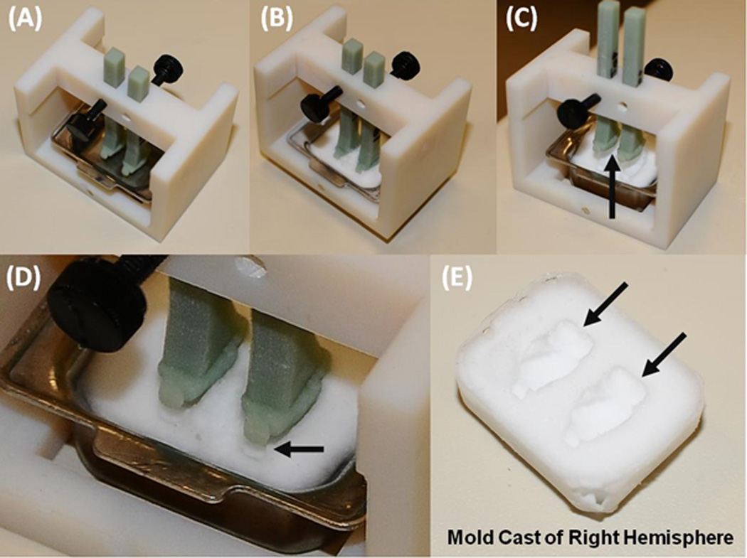
The assembled freezing platform, with the base-mold and two hemisphere models. Embedding medium is added to the base-mold, to just barely cover the hemisphere models, and then the platform is frozen in a −80C freezer (B). The fixture is allowed to acclimate to room-temperature for ten minutes. The hemisphere models are then raised and the base-mold is removed, by rocking it side-to-side. The cast-mold will separate from the hemisphere models, as shown in (C) and at higher-magnification in (D). The black arrow points to the area of separation. The resulting cast-mold is shown in (E). The black arrows point to the formed cavities of the two brains.
Figure 7. Coronal sections of two brains, processed using the Pre-Cast Mold System and Classical Stereotaxic Blocking.
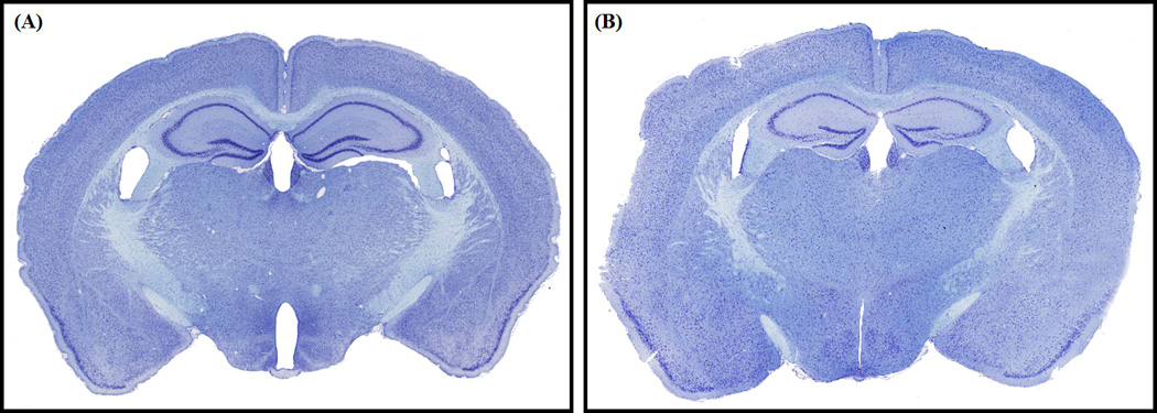
(A) A brain processed using the Pre-Cast Mold System. (B) A brain prepared using classical stereotaxic blocking, in which the head of the perfused animal was aligned on the stereotax and a razorblade was used to mark the coronal plane. The sections roughly correspond to plate 68 of Allen Reference Atlas. The sections appear well aligned to each other and to the Allen Reference Atlas.
Highlights.
A standardized method to freeze and section mouse brains in stereotaxic coordinates
Two brains are placed into pre-formed cavities that are comprised of embedding medium
The cavities are pre-aligned to the canonical planes of section
Two brains can be frozen and sectioned simultaneously
The disposable cost of this method is 20× less than a similar alternative
Acknowledgements
This work is part of the Mouse Brain Architecture Project and was supported by a Challenge Grant from the National Institutes of Health (RC1MH088659), a Transformative Award from the Office of the NIH Director (R01MH087988), the Crick-Clay Professorship and internal funding from Cold Spring Harbor Laboratory. We thank Dr. Kathleen Rockland for encouragement, advice, and significant help with manuscript preparation. We also thank the Allen Institute for Brain Science for providing access to the volumetric anatomical atlas of the left-hemisphere and Dr. Jason Bohland, for converting that volume into a smoothed 3-D model of the brain.
Footnotes
Publisher's Disclaimer: This is a PDF file of an unedited manuscript that has been accepted for publication. As a service to our customers we are providing this early version of the manuscript. The manuscript will undergo copyediting, typesetting, and review of the resulting proof before it is published in its final citable form. Please note that during the production process errors may be discovered which could affect the content, and all legal disclaimers that apply to the journal pertain.
References
- Beltz B, Paul CA, Berger-Sweeney J. Discovering Neurons: The Experimental Basis of Neuroscience. Cold Spring Harbor Press; 1997. [Google Scholar]
- Dong HW, Science TAIfB. The Allen Reference Atlas. Wiley; 2008. [Google Scholar]
- Jiang X, Kalajzic Z, Maye P, Braut A, Bellizzi J, Mina M, Rowe DW. Histological analysis of GFP expression in murine bone. J Histochem Cytochem. 2005;53:593–602. doi: 10.1369/jhc.4A6401.2005. [DOI] [PubMed] [Google Scholar]
- Peters SR. A Practical Guide to Frozen Section Technique. Springer; 2009. [Google Scholar]
- Salie R, Li H, Jiang X, Rowe D, Kalajzic I, Susa M. A Rapid, Nonradioactive In Situ Hybridization Technique for Use on Cryosectioned Adult Mouse Bone. Calcified Tissue International. 2008;83:212–221. doi: 10.1007/s00223-008-9154-1. [DOI] [PubMed] [Google Scholar]
- Zeller R. Fixation, embedding, and sectioning of tissues, embryos, and single cells. Chapter 14: Unit 14 1. In: Frederick M, Ausubel, et al., editors. Current protocols in molecular biology. 2001. [DOI] [PubMed] [Google Scholar]


