Abstract
This paper presents the development and evaluation of video augmentation on the stereoscopic da Vinci S system with intraoperative image guidance for base of tongue tumor resection in transoral robotic surgery (TORS). Proposed workflow for image-guided TORS begins by identifying and segmenting critical oropharyngeal structures (e.g., the tumor and adjacent arteries and nerves) from preoperative computed tomography (CT) and/or magnetic resonance (MR) imaging. These preoperative planned data can be deformably registered to the intraoperative endoscopic view using mobile C-arm cone-beam computed tomography (CBCT) [1, 2]. Augmentation of TORS endoscopic video defining surgical targets and critical structures has the potential to improve navigation, spatial orientation, and confidence in tumor resection. Experiments in animal specimens achieved statistically significant improvement in target localization error when comparing the proposed image guidance system to simulated current practice.
Keywords: Transoral Robotic Surgery, Stereoscopic Video Augmentation, Intraoperative Image Guidance, Cone Beam Computed Tomography, Minimally Invasive Surgery, Deformable Registration
INTRODUCTION
Transoral robotic surgery (TORS) is a minimally invasive surgical intervention to treat oropharyngeal cancer, including resection of base of tongue tumors. Developed by Weinstein et al. [3] and approved in 2009 by the US Food and Drug Administration for use in select benign and malignant tumors of the head and neck, TORS is an increasingly utilized option in addressing the growing incidence of oropharyngeal cancer. TORS offers an attractive treatment modality with reduced morbidity, functional deficit, and toxicity compared to conventional regimens of combined chemotherapy and radiation therapy [4].
Base of tongue tumors present a unique challenge for TORS. Most base of tongue tumors are buried deep in the musculature of the tongue, presenting a challenge to clearly visualize all but the most superficial aspects of the tumor. This “tip-of-the-iceberg” phenomenon combined with an inability to palpate the tongue base during robotic surgery and potential injury to neurovascular structures jeopardize reliable and safe delineation of tumor margins. This is compounded by the fact that pre-operative imaging of the tongue in repose may not accurately reflect the tumor position when the tongue is retracted and deformed during surgery. Expert surgeons rely on experience to remain correctly oriented with respect to critical anatomy, even after tissue deformation, by intuitively mapping preoperative data to the highly deformed surgical field. Such practice leaves considerable room for improvement and may lead to compromised margins and ultimately recurrent disease.
We propose identifying critical structures (e.g., the tumor, adjacent arteries, and nerves) in diagnostic preoperative CT and/or MR and creating a detailed surgical plan that can be integrated with endoscopic video in the operating room. A cone-beam computed tomography (CBCT) acquired immediately after the patient is positioned for robotic surgery captures intraoperative deformation. Deformable registration of preoperative CT to intraoperative CBCT creates an intraoperative surgical plan to be registered with the robotic endoscopy [5]. Augmentation of TORS endoscopic video with planning data defining the target and critical structures offers the potential to improve navigation, spatial orientation, confidence, and tissue resection. This paper presents initial development and evaluation of video augmentation using intraoperative CBCT and the stereoscopic da Vinci S surgical system (Intuitive Surgical, Sunnyvale, California) for base of tongue tumor resection.
METHODS
System Overview
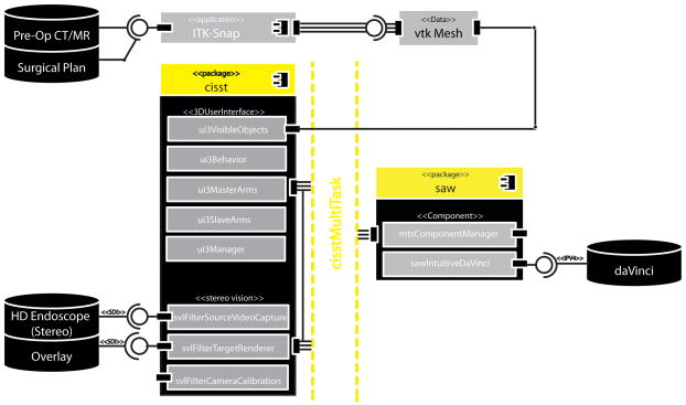
Stereoscopic video augmentation was achieved with a modular architecture, illustrated in Fig. 1., by extending the cisst3DUserInterface (3DUI), and cisstStereoVision (SVL) libraries from the cisst/Surgical Assistance Workstation (Saw) open-source toolkit [6], developed at the Engineering Research Center for Computer Integrated Surgery (CISST ERC) at the Johns Hopkins University. As a preoperative planning step, critical data (i.e., the tumor, lingual/carotid artery, lingual nerve, etc.) as well as registration fiducials were manually segmented from preoperative CT and/or MR images using ITK-Snap. These structures, saved in Visualization Toolkit (VTK) [7] formats, were loaded onto a Dell Precision T7500 with dual 6-core Intel Xeon processors, running Ubuntu Linux. The research desktop takes dual HD-SDI SMPTE 274 (1080i@59.94Hz) video signals from the da Vinci camera control units, computes virtual scene updates, and overlays augmented dual HD-SDI channels back into the visual core of the robotic system. Initially, planning data were stippled for transparency as the system employed two Matrox Vio (Quebec, Canada) PCIe video capture cards with overlay input and passive video throughput. These cards have been replaced with a single Nvidia Quadro SDI Capture Card (Santa Clara, CA, USA), allowing for a more natural blend of the native endoscopy and image guidance through active dual stream alpha-blended overlays.
Figure 1.
UML component diagram detailing the libraries supporting stereo video augmentation and modular design of the proposed intraoperative image-guided TORS system.
The 3DUI library is comprised of classes that support VTK data structures of the surgical plan, additional objects for 3D rendering and behaviors, classes that process user inputs to update the augmented 3D scene. This includes VTK cameras, renderers, and actors that represent the segmented clinical information as well as graphical composition and management of the user interface. The 3D scene, rendered to the surgeon console, also includes a virtual menu accessible via the master manipulators (MTMs), allowing for dynamic modifications of the overlay for a surgeon’s preference of color, opacity, and feedback throughout the procedure. Therefore while we augment both the visual field and user interface of the surgeon console of the da Vinci S, the enhancement is accomplished through the standard robotic interface, familiar to clinical users. A SAW component wraps the application programming interface (API) of the da Vinci S, provided through CISST ERC’s research collaboration with Intuitive Surgical, Inc. This component is created with a provided interface that relays robotic system events, status, and manipulator data that are connected to callback functions required by behaviors of the 3DUI library. Connections between components and behaviors are established and supervised by a component manager, a class of the cisstMultiTask (MTS) library. Thus events from the da Vinci surgeon console such as clutching, camera movement, master manipulator movement, and resultant real-time joint positions of patient-side manipulators (PSMs) are communicated across a component-based framework from the robot to 3DUI in a modular architecture [cisstMultiTask layer in Fig. 1]. The MTS library decouples the input/output device (da Vinci S) and the image navigation software into separate components exposed through interfaces. This modular design supports modifications within elements and the exchange of entire components for flexibility and extendibility.
Video to CBCT Registration
Registration of endoscopic video with the surgical plan, segmented from preoperative CT, is derived with the following series of transformations (1):
| (1) |
Experiments presented in this work simplified the registration process by assuming that the CBCTTCT transform (i.e., the deformable registration of preoperative CT to intraoperative CBCT) was known. The deformable registration process is the subject of other work [5], involving a combination of rigid and non-rigid transformations based on Gaussian mixture models and the Demons algorithm. Therefore, planned data was segmented directly from intraoperative CBCT, creating DataCBCT registered with equation (2).
| (2) |
Adequate visibility of the surgical target directly in preoperative CT or intraoperative CBCT may be an idealized scenario, and preoperative MR will likely offer better delineation of soft tissues, including the tumor and lingual nerves, while preoperative CT with contrast will enhance arteries of interest, such as the lingual and carotid artieries. Although these initial experiments assumed target visibility directly in intraoperative CBCT, the deformable registration process under development [5] is designed to accommodate preoperative CT and/or MR in the proposed workflow.
Planned data was registered to the robotic endoscope through a manual process, where fiducials, segmented in CBCT were identified by the operator with 3DUI virtual cursors using MTMs. Optionally the operator could physically identify these registration fiducials by placing tool tips of the PSMs directly onto the sphere, but this would require robot-to-tooltip calibration to account for offsets within the setup joints of the robotic arm, a topic of future work. These corresponding data provide the rigid point-based transformation, VideoTCBCT. Using the standard camera controls at the surgeon console, as the operator adjusts the endoscope, the joint positions of the robotic endoscope arm are communicated to the 3DUI.
Coordinate Systems
The 3DUI behavior manages the objects used for registration and video augmentation. It maintains a hierarchy of coordinate systems (CS) and the objects that are stored relative to each branch [Fig. 2]. Relative transformations between CS are updated based on user input and registration steps in the workflow. Serving as the root node, CS 3DUI, anchors this transformation tree. The motion of the da Vinci camera is reported by the API as the movement of the endoscope center of motion (ECM) with respect to the Remote Center of Motion (RCM) of the endoscope’s PSM. A static rotation in 180° about the y-axis aligns the surgeon’s console to 3DUI. Transformation of the ECM to RCM is updated when the surgeon moves the camera on the SC by computing the forward kinematics of the endoscopic joint positions. Triggered by the camera pedal “press” events and using real-time joint positions, the 3DUI computes the displacement of the endoscopic center of motion and continuously updates VideoTCBCT to maintain the registration of the overlay.
Figure 2.
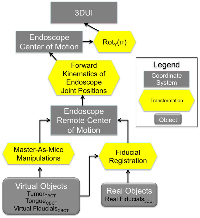
Transformation tree depicting the coordinate systems and associated objects maintained by the video augmentation program through tracking of the daVinci and registration steps.
When the da Vinci clutch pedal is activated, the surgeon can move the MTMs while the PSMs remain stationary. In the 3DUI behavior we take advantage of this setting by implementing a mode termed “Master-As-Mice.” In this mode the surgeon can access a 3D menu using the MTMs rendered as 3D cursors. Features supported include fiducial-based registration, visibility toggle and direct manipulation of the overlaid objects, allowing the surgeon to manipulate and review the virtual scene as well as refine the overlay registration all within the native 3D viewport of the SC. A single activation of an MTM (left or right) translates the virtual objects. If both master manipulators are activated, the movement the 3DUI objects follow the rigid transformation of the segment between the MTMs at the centroid. These motions therefore only displace the virtual objects whose transformations are maintained with respect to the CS of the RCM.
TORS Phantoms
Rigid and deformable phantom studies were conducted to measure the accuracy of the overlaid image guidance and effect on target localization. A rigid anthropomorphic skull phantom derived from 3D rapid prototyping modeled from a cadaver CT scan [8] was used to assess the accuracy of the video overlay. Five fiducials on the skull surface and visible in CBCT were manually segmented for video to CBCT registration. Additionally, three target fiducials, embedded near the soft palate are also localized to assess the target localization error (TLE) (Projection), i.e., the shortest distance between the overlaid CT targets and rays through the visible target seen through both cameras.
In preoperative CT or MR a patient is typically supine with his/her mouth closed and tongue in repose filling the oropharynx. Intraoperatively, the patient’s neck is extended with the mouth open and the tongue pulled anteriorly and depressed with a mouth retractor, such as the Feyh-Kastenbauer (FK) retractor (Gyrus ACMI/Explorent GmbH, Tuttlingen Germany) [4]. This places the tongue in an extended, curved position. Using a custom frame in place of a standard retractor, the large deformation from the intraoperative setup [Fig. 3(h)] as compared to the preoperative pose [Fig. 3(g)] is demonstrated here in CBCT of a cadaver acquired for testing of the deformable registration method [5]. Stainless steel mouth gags/metal mouth retractors, such as the FK or Crow-Davis, are centrally located in the volume of interest and will certainly cause metal artifacts in CBCT. Radio-translucent replacements would eliminate these problems, and reconstruction algorithms including metal artifact correction or more advanced methods such as model-based Known-Component Reconstruction [9] can also help to overcome such artifacts but is left for future work. For the purposes of the porcine tongue experiments, we fabricated custom acrylic frames, laser cut using computer-aided design models and etched with reusable fiducials to be imaged within a (15 × 15 × 15) cm3 volumetric field-of-view of the intraoperative C-arm [2]. These include foam templates [Fig. 3(a,d)] placing the porcine tongues in the flat preoperative [Fig. 3(b)] and curved intraoperative [Fig. 3(e)] positions with deformations as seen in CBCT in Fig. 3(c), (f), respectively.
Figure 3.
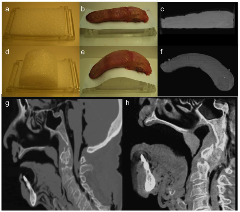
TORS phantom with (a) the preoperative template in an acrylic frame to house (b) a preoperatively posed porcine tongue, and (c) its corresponding preoperative CBCT. TORS phantom with (d) the intraoperative template in an acrylic frame to house (e) an intraoperatively posed porcine tongue, and (c) its corresponding intraoperative CBCT. CBCT of a cadaver specimen placed in preoperative pose (g) (tongue in, mouth closed) compared to intraoperative deformation (h) (neck flexed, mouth open, tongue extended).
Experiment on the TORS Robot
Experimentation using porcine tongue phantoms with a da Vinci S robot was conducted to evaluate the effect of intraoperative imaging and navigation through video augmentation. Three porcine tongues (each embedded with eight soft-tissue targets, [red in Fig. 4(a)] were imaged with CBCT first in the flat, preoperative pose and then the intraoperative, curved positions described above. Eight 1.6 mm diameter nylon fiducials (yellow in Fig. 4(a)) were affixed to the tongue surface as registration fiducials. A fellowship-trained head and neck surgeon expert in use of the da Vinci S was tasked to place a needle in each target of the curved tongue phantom with variants in image guidance as follows:
Figure 4.
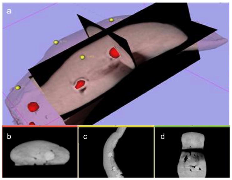
(a) Surgical plan, in 3D Slicer (namic kit, Brigham & Women’s Hospital, Cambridge MA), with surface and target VTK meshes segmented from the intraoperative CBCT of a pig tongue specimen, embedded with spherical targets. (b–d) Triplanar axial slices of intraoperative CBCT.
| • Phantom 1 | (P-1) | Represents current practice by presenting the surgeon with preoperative imaging displayed in 2D on an adjacent laptop. |
| • Phantom 2 | (P-2) | Replaces preoperative imaging with intraoperative CBCT of the deformed tongue still displayed in 2D on an adjacent laptop. |
| • Phantom 3 | (P-3) | Characterizes our proposed workflow with a surgical plan derived from intraoperative CBCT which is overlaid onto the 3D endoscopy of the daVinci surgeon console. |
P-1 and P-2 are presented in the traditional triplanar views of the 3D volume in a standard display separate from the surgeon console. The inclusion of P-2 allows assessment of the influence of intraoperative imaging only, without visual integration with the surgeon’s direct endoscopic field of view. A photograph of the surgeon during the P-3 run utilizing the research da Vinci S platform augmented with the segmented targets (inset, pink) overlaid and registered onto the stereoscopic scene is show in Figure 5.
Figure 5.
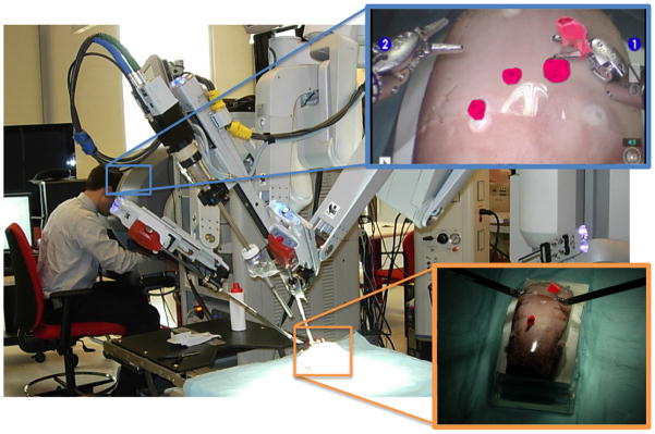
Experimental setup using a da Vinci S system with stereoscopic video overlay of spherical soft-tissue targets (magenta) segmented from intraoperative CBCT.
RESULTS
Phantom Experiments
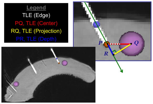
From postoperative CBCT scans of the deformed tongue, the needle axis, tip, target centers, and target edge were segmented manually. Target localization error (TLE) was analyzed in four ways: Edge, Center, Projection, and Depth. The TLE (Edge) characterized the distance between the needle tip and the closest edge of the target (with needles placed on or inside the target assigned a TLE of zero), most closely emulating the task of needle placement. Denoting the needle tip P, and projecting the center of the target, Q, onto the needle axis and denoting that point R, then TLE (Center) is the line segment PQ [Fig 6]. We deconstruct PQ into segments along the needle, PR, and orthogonal to the needle, RQ, as TLE (Depth) and TLE (Projection), respectively.
Figure 6.
The deconstruction of target localization error into 4 types: TLE (Edge, Center, Projection, Depth) is shown on a sagittal slice of a CBCT of a porcine tongue phantom following robotic experimentation. 4mm radius spheres, targets (pink) were manually segmented along with a needle tip (orange) and needle axis (purple).
Initial results of the TLE from porcine tongue experiments with the TORS robot are summarized in 1 with box plots of TLE (Edge) in Fig. 6. The mean TLE (Edge) improves from (4.9±4.6) mm, (3.9±3.3) mm, and (1.7±1.8) mm for P-1 to P-3, respectively. Results also show TLE (Center) improving from (9.8±4.0) mm, (8.9±2.9) mm, and (6.7±2.8) mm, for P-1 to P-3, respectively. Deconstructing TLE (Center) into its projection and depth components shows that the overlay improved TLE (Projection) by more than 3 mm, with P-1 giving (6.4±3.3) mm, P-2 giving (6.2±1.7) mm, and P-3 giving (3.3±2.0) mm. However, the improvement in TLE (Depth) is noticeably smaller, at less than 1 mm. Comparable TLE (Depth) for P-2 and P-3 suggests that intraoperative imaging was the source for the decrease in depth error as opposed to an effect from image guidance through overlay. These results indicate that while stereoscopic overlay assists with localization within the camera image plane, more feedback regarding depth, orthogonal to the image, i.e. within the epipolar plane, could reduce the overall TLE. In fact, significance of subsurface information in image guidance systems has been investigated for similar robotic interventions [10].
Using stereoscopic video augmentation, the surgeon was able to place a needle inside 25% of the targets on P-3, compared to 0% for P-1 and P-2.Improvements between P-1 and P-2 indicated a positive influence of intraoperative imaging, while a larger improvement between P-2 and P-3 reinforces the value of visualizing image data directly in the surgeon’s natural endoscopic window. Additionally for TLE (Edge), a p-value of 0.048 between P-1 and P-3 demonstrates statistical significance between simulated current practice (unregistered preoperative imaging) and the proposed image guidance system, evidencing the potential value of intraoperative imaging and navigation through video augmentation to improve target localization in TORS.
DISCUSSION
Transoral robotic surgery has become an increasingly prevalent technique to resect oropharyngeal cancer. It offers a curative, minimally invasive intervention with improved long-term quality of life outcomes. Despite encouraging oncologic and functional results there remain barriers to its adoption. Infiltrative, submucosal base of tongue cancers present a particular challenge. The surgeon must rely on preoperative imaging of a tumor that may deform substantially with the patient in the operative position with mouth open and tongue extended. The base of tongue also lacks conspicuous anatomical landmarks to help guide the surgeon safely around the tumor while maintaining an adequate oncologic margin. Registering critical anatomy from preoperative CT and/or MR allows navigation to oncologic targets and around functional oropharyngeal structures. Furthermore, increased confidence in surgical intervention for ororpharyngeal cancer has the potential to improve post-operative management not only for surgeons but for radiation oncologists, medical oncologists, and speech-language pathologists.
Computer-assisted interventions have been applied to similarly high-risk and complex, minimally-invasive procedures [11]. Enhanced visualization and intraoperative information support has been achieved with various imaging modalities, such as ultrasound [12], CBCT [1, 2], and optical 3D reconstruction using stereoscopic laparoscopes and computational stereo [13]. Visualization and feedback is often accomplished through rendering of virtual or simulated environments [14] or tracking of operative tools within the preoperative image data. For example, conventional skull base endoscopy incorporates pointer tracking to provide registration with preoperative CT or MR. However, these 3D volumes, often presented in a traditional triplanar view of the radiological axes, do not emphasize the target or critical structures [15]. Furthermore, these views are often rendered separately from the endoscopic video and only remain registered if the pointer is within the field of view. Surgeons are required to mentally register the information from the triplanar views with the video scene. In the context of increasingly complex anatomy for endoscopy and laparoscopy that navigate in proximity to critical structures, presenting additional information derived from multi-modality imaging to the surgeon directly within the primary means of visualization (i.e. the endoscopic video) provides a more natural “window”.
A system for intraoperative image-guided transoral robotic surgery using a research da Vinci S robot has been presented and evaluated. The workflow proposes using surgical plans derived from preoperative CT or MR to be deformably registered to intraoperative CBCT. This captures patient setup deformation in the operating room while directly integrating rich, multi-modal preoperative data delineating the cancer target as well as critical functional anatomy within the surgeon’s natural field of view. The experimental results tasking target localization within custom porcine phantoms show statistically significant improvement in TLE Edge lowered to 1.7±1.8 mm when using the proposed workflow in comparison to simulated current practice. Although a hit ratio of 25% leaves considerable room for improvement, a larger number of surgeon subjects, phantom experiments, and increased targets for each phantom would better evaluate a comprehensive utilization of the image guidance system. A future study will include Otolaryngology-Head and Neck residents training in TORS to determine the effectiveness of the system for non-expert / novice surgeons. Currently, methods of training residents on the daVinci for TORS [16] typically involve resection of an embedded sphere from tongues of porcine animal phantoms, and results are evaluated by measuring margins surrounding the target from the resected sample. Overlay of the tumor in addition to subsurface information would assist in achieving adequate negative margins, crucial to prevent recurrence of disease in clinical practice.
The modular architecture of this design supports extension for additional intraoperative image updates, systematic component refinement, as well as expansion for other applications. For example, the user interface and classes supporting robotic input/output (IO) were unaffected with the upgrades to the rendering hardware since changes occurred only within the SVL library. This design can therefore be extended to other robotic systems or IO hardware, including 6 degrees of freedom haptic devices, such as the Sensable Phantom Omni (Wilmington, MA, USA) as a portable test platform. Other clinical interventions may use different endoscopes, tracking devices, robots, etc., all of which can be interfaced with minimal changes isolated within a specific library designated in the UML diagram of Fig. 1.
Although preliminary phantom results on TLE have been promising, experiments reported did not integrate a deformable registration of preoperative CT to intraoperative CBCT, i.e. CBCTTCT, which is likely a critical step for the proposed image guidance workflow. Image guidance with overlay conducted thus far assumes target visibility directly within intraoperative CBCT to be adequate for segmentation and derivation for intraoperative surgical plans. Next steps will integrate an appropriate deformable registration algorithm [5] to complete the proposed workflow followed by new experiments to test the effect of using registered preoperative CT plans for image-guided TORS. Furthermore, preoperative planning data reflects patient anatomy only on approach for surgical intervention. Once the patient tissue has been surgically altered, image data used for guidance will need to be updated. To update the navigation image data for a modified surgical field, we will look to incorporate additional CBCT acquisitions, 3D ultrasound, and other intraoperative imaging modalities.
Future work will also involve improvements in visualization and feedback, including rendering of cues for depth perception and out-of-camera-plane information. This requires registration and tracking of robotic tool tip to camera in addition to the video to CBCT registration, depicted in equation (1). Other transformations in this equation, i.e. VideoTCBCT, may also be refined with additional methods such as registration of 3D structures recovered from disparity and motion [17, 18]. Future work should also consist of a comprehensive system analysis on the entire proposed image guidance workflow tandem to intrinsic accuracies of the robotic system [19] to determine error sources and propagation as a priori to systematic refinement.
Figure 7.
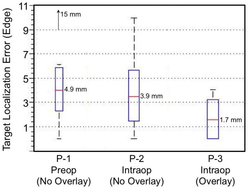
Box plot of the Target Localization Error (Edge) in the three experimental image guidance scenarios.
Table 1.
Summary of target localization error (Center, Edge, Projection, Depth) from 3 porcine tongue TORS experiments under various forms of image guidance. TLE (Edge) between P-1 and P-3 has p-value = 0.048 (red).
| Phantom | Image Data | Overlay | TLE (Center) [mm] | TLE (Edge) [mm] | TLE (Projection) [mm] | TLE (Depth) [mm] | Hit Ratio | ||||||||
|---|---|---|---|---|---|---|---|---|---|---|---|---|---|---|---|
| Mean | STDDev | Max | Mean | STDDev | Max | Mean | STDDev | Max | Mean STDDev | Max | |||||
| P-1 | Preop | No | 9.8 | 4.0 | 18.5 | 4.9 | 4.6 | 15.0 | 6.4 | 3.3 | 11.3 | 6.6 | 4.0 | 14.6 | 0/8 |
| P-2 | Intraop | No | 8.9 | 2.9 | 15.4 | 3.9 | 3.3 | 9.9 | 6.2 | 1.7 | 8.7 | 5.5 | 4.1 | 14.5 | 0/8 |
| P-3 | Intraop | Yes | 6.7 | 2.8 | 9.8 | 1.7 | 1.8 | 4.1 | 3.3 | 2.0 | 6.0 | 5.3 | 3.3 | 9.3 | 2/8 |
Acknowledgments
This research is supported in part by Intuitive Surgical Inc. and by Johns Hopkins University. The authors extend sincere thanks to Dr. Iulian Iordachitaand Woo Jin Kim for assistance with tongue phantom fabrication and to Dr. Sebastian Schafer for CBCT acquisitions. The C-arm CBCT prototype was developed in academic-industry partnership with Siemens XP (Erlangen, Germany) with thanks to Dr. Rainer Graumann and Dr. Gerhard Kleinszig. Support was provided from NIH-R01-CA-127444, NSF EEC9731748, and the Swirnow Family Foundation.
Footnotes
Conflicts of Interest:
Wen P. Liu is a student fellow sponsored by Intuitive Surgical, Inc.
Jeremy Richmon, MD is a consultant for Intuitive Surgical, Inc.
Jonathan M. Sorger is the Director of Medical Research at Intuitive Surgical, Inc.
References
- 1.Daly MJ, et al. Intraoperative cone-beam CT for guidance of head and neck surgery: Assessment of dose and image quality using a C-arm prototype. Med Phys. 2006;33(10):3767–80. doi: 10.1118/1.2349687. [DOI] [PubMed] [Google Scholar]
- 2.Siewerdsen JH, et al. High performance intraoperative cone-beam CT on a mobile C-arm: an integrated system for guidance of head and neck surgery. SPIE Medical Imaging; 2009; Orlando. [Google Scholar]
- 3.Weinstein GS, et al. Transoral robotic surgery alone for oropharyngeal cancer: an analysis of local control. Arch Otolaryngol Head Neck Surg. 2012;138(7):628–34. doi: 10.1001/archoto.2012.1166. [DOI] [PubMed] [Google Scholar]
- 4.Weinstein GS, O’Malley BW. TransOral Robotic Surgery (TORS) San Diego, CA, USA: Plural Publishing, Inc; 2012. [Google Scholar]
- 5.Reaungamornrat S, et al. A Gaussian Mixture + Demons Deformable Registration Method for Cone-Beam CT-Guided Robotic Transoral Base-of-Tongue Surgery. SPIE Medical Imaging; 2013; Orlando. [Google Scholar]
- 6.Deguet A, et al. The cisst libraries for computer assisted intervention systems. MICCAI Workshop; 2008. https://trac.lcsr.jhu.edu/cisst/ [Google Scholar]
- 7.Pieper S, et al. The NA-MIC kit: ITK, VTK, pipelines, grids, and 3D Slicer as an open platform for the medical image computing community. Proc IEEE Intl Symp Biomed Imag. 2006;(April):698–701. [Google Scholar]
- 8.Vescan AD, et al. C-arm cone beam CT guidance of sinus and skull base surgery: quantitative surgical performance evaluation and development of a novel high-fidelity phantom. 2009;7261:72610L–10. [Google Scholar]
- 9.Stayman JW, et al. Model-based tomographic reconstruction of objects containing known components. IEEE Trans Med Imaging. 2012;31(10):1837–48. doi: 10.1109/TMI.2012.2199763. [DOI] [PMC free article] [PubMed] [Google Scholar]
- 10.Herrell SD, et al. Toward image guided robotic surgery: system validation. J Urol. 2009;181(2):783–9. doi: 10.1016/j.juro.2008.10.022. discussion 789–90. [DOI] [PubMed] [Google Scholar]
- 11.Cash DM, GS, Clements LW, Miga MI, Dawant BM, Cao Z, Galloway RL, Chapman WC. Concepts and Preliminary Data towards the Realization of an Image-Guided Liver Surgery. Journal of Gastrointestinal Surgery. 2007;11(7):844–859. doi: 10.1007/s11605-007-0090-6. [DOI] [PMC free article] [PubMed] [Google Scholar]
- 12.Klein T, Hansson M, Navab N. Modeling of Multi-View 3D Freehand Radio Frequency Ultrasound. Medical Image Computing and Computer-Assisted Interventions (MICCAI-2012); 2012; France. [DOI] [PubMed] [Google Scholar]
- 13.Stoyanov D. Stereoscopic Scene Flow for Robotic Assisted Minimally Invasive Surgery. Medical Image Computing and Computer-Assisted Interventions (MICCAI-2012); 2012; France. [DOI] [PubMed] [Google Scholar]
- 14.Schulze F, et al. Intra-operative virtual endoscopy for image guided endonasal transsphenoidal pituitary surgery. Int J Comput Assist Radiol Surg. 2010;5(2):143–54. doi: 10.1007/s11548-009-0397-8. [DOI] [PubMed] [Google Scholar]
- 15.Desai SC, Sung CK, Genden EM. Transoral robotic surgery using an image guidance system. Laryngoscope. 2008;118(11):2003–5. doi: 10.1097/MLG.0b013e3181818784. [DOI] [PubMed] [Google Scholar]
- 16.Curry M, et al. Objective assessment in residency-based training for transoral robotic surgery. Laryngoscope. 2012;122(10):2184–92. doi: 10.1002/lary.23369. [DOI] [PMC free article] [PubMed] [Google Scholar]
- 17.Zhang L, Curless B, Seitz S. Computer Vision and Pattern Recognition. 2003. Spacetime Stereo: Shape Recovery for Dynamic Scenes. [Google Scholar]
- 18.Tombari F, et al. A 3D Reconstruction System Based on Improved Spacetime Stereo. International Conference Control Automation, Robotics and Vision; 2010; Singapore. [Google Scholar]
- 19.Kwartowitz DM, Herrell SD, Galloway RL. Update: Toward image-guided robotic surgery: determining the intrinsic accuracy of the daVinci-S robot, International Journal of Computer Assisted Radiology and Surgery. Journal of Computer Assisted Radiology and Surgery. 2007;1(5):301–304. [Google Scholar]


