Abstract
Planar electronics processing methods have enabled neural interfaces to become more precise and deliver more information. However, this processing paradigm is inherently 2D and rigid. The resulting mechanical and geometrical mismatch at the biotic–abiotic interface can elicit an immune response that prevents effective stimulation. In this work, a thiol–ene/acrylate shape memory polymer is utilized to create 3D softening substrates for stimulation electrodes. This substrate system is shown to soften in vivo from more than 600 to 6 MPa. A nerve cuff electrode that coils around the vagus nerve in a rat and that drives neural activity is demonstrated.
Keywords: flexible electronics, neural interfaces, shape memory polymers, stimuli-sensitive polymers, thermosets
1. Introduction
Interaction with the peripheral and central nervous system is likely to enable improved treatment of a wide variety of neurological disorders and impairments.[1] This interaction is enabled by neural interfaces designed to both stimulate and record neural activity.[2,3] These devices have taken on countless shapes and forms to interface with a wide variety of biological structures.[4,5] A major focus has been on the development of high-density electrodes using rigid, planar, substrates, such as silicon. Consequently, there is a large mechanical and geometrical mismatch between the neural interface and the highly compliant neural tissue.[6,7] This mismatch restricts the type of biological structures that can be accessed and aggravates the foreign body response and limits longevity. A nerve cuff (electrodes that wrap around a nerve) is one example of a device that is particularly poorly suited to planar fabrication techniques.[8,9] Cuff electrodes have been used in neuroscience for the stimulation of the vagus nerve to induce neural plasticity for the treatment of tinnitus, stroke, and other disorders as well as reduce epileptic seizures.[10,11]
Several approaches have been utilized to reduce the geometrical and mechanical mismatch of neural interfaces. The broad field of flexible electronics has primarily either used elastomers or engineering thermoplastics to fabricate more compliant interfaces.[12] Engineering thermoplastics such as polyimides and Parylene-C are compatible with photolithography and have sufficient rigidity to allow surgical implantation, but have a nearly four orders of magnitude higher modulus than neural tissue, which ranges from 10 kPa to 0.5 MPa.[8,13,14] Elastomers, such as silicones, have also been used, but high compliance, while desirable after implantation, complicates planar processing (if used) and implantation.[12,15] There are several examples of cuffs combining elastomers and other closing mechanisms such as hinges and a shape memory alloy armature.[16–18] These devices share the same goal as this work to ensure an intimate interface between the nerve and a compliant substrate. More recently, two examples of softening intracortical recording multielectrode arrays capable of behaving in a rigid manner during planar processing and implantation and subsequently softening have been demonstrated.[19–22] This new generation of responsive, softening neural interfaces is beginning to address problems caused by mechanical mismatch with tissue.
Shape memory polymers (SMPs) are smart materials capable of storing a metastable shape and returning in a controlled manner to a globally stable shape upon response to a stimulus, such as heat or light.[23–25] This triggered response is often a thermally induced phase transformation such as a melting or glass transition.[26] In addition to the shape change, a dramatic change in modulus may be observed.[27] There are, however, several key challenges associated with SMPs that have received attention in the literature. One such problem is the poor processability of thermoset polymers commonly used as SMPs. Due to the conditions required for the synthesis of many thermosets, including high temperatures, sensitivity to oxygen, and the formation of high-cure stresses, post-polymerization crosslinking has been investigated on several systems.[28,29] This approach allows for the formation of thermoset polymers in shapes other than the shape of the initial polymerization, enabling SMPs with thermoset properties that can recover increasingly complicated shapes.
A number of thermosetting polymers have been demonstrated as useful SMPs, including thiol–ene polymers. The thiol–ene reaction has been described as a “click” reaction for its versatility and facile reaction conditions required to achieve high conversion, even in bulk.[30] Specifically the thiol–ene reaction can proceed through a radical mechanism and result in the stoichiometric addition of thiols to a wide number of alkenes. The resulting polymers of multifunctional thiols and enes have been shown to form highly uniform networks.[31] The presence of the flexible thioether linkage, however, has limited the ability to synthesize polymers with high-glass transition temperatures (Tg).[32] A slightly modified version of the thiol–ene reaction is the ternary thiol–ene/acrylate reaction where both acrylate homopolymerization and thiol–ene reactions proceed simultaneously.[33,34] This has been shown to be a useful manner of increasing crosslink density and subsequently Tg.
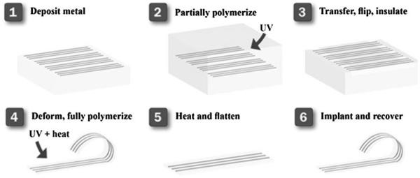
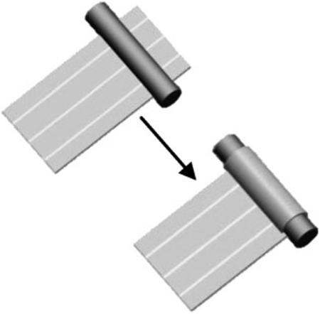
In this work, an amorphous ternary thiol–ene/acrylate thermoset SMP is designed, fabricated, and characterized as a substrate for a nerve cuff electrode capable of both softening and changing shape in response to physiological conditions. Specifically the flexible (not soft) cuff can be inserted under the nerve in a planar state, and upon reaching physiological conditions, coil and soften to bring the electrodes into contact with the nerve. The concept and associated manufacturing paradigm is demonstrated schematically in Figure 1. A novel process is described where electrodes are patterned onto a planar sacrificial substrate, transferred to a partially reacted substrate, insulated, and through completing the polymerization given a final shape which conforms to a nerve. This is accomplished through temporal control of the thiol–ene/acrylate reaction. Finally a functioning nerve cuff is demonstrated both in vitro and in vivo.
Figure 1.
Schematic of the manufacturing of a 3D SMP nerve cuff. Metal electrodes are desposited through a shadow mask onto a sacrficial glass substrate. These electrodes are transferred to a partially polymerized substrate, and an insulation layer is cast onto the electrodes. The electrodes are then deformed into the desired final shape and the polymerization completed, thus setting this shape. This device can then be deformed away from the final shape to enable implantation and will recover in vivo.
2. Experimental Section
2.1. Materials
Tricyclodecane dimethanol diacrylate (TCMDA), 1,3,5-triallyl-1,3,5-triazine-2,4,6(1H,3H,5H)-trione (TATATO and 2,2-dimethoxy-2-phenyl acetophenone (DMPA) were purchased from Sigma–Aldrich. Tris[2-(3-mercaptopropionyloxy)ethyl] isocyanurate (TMICN) was purchased from Wako Chemicals. All chemicals were used as received without further purification. All processing steps except polymer synthesis were performed in a Class 10 000 cleanroom.
2.2. Dynamic Mechanical Analysis
DMA was performed on a Mettler Toledo DMA 861e/SDTA. Samples were cut into cylinders approximately ≈1.2 mm thick and ≈3 mm in diameter. The mode of deformation was shear, and strain was limited to a maximum of 0.3%. Samples were tested at a heating rate of 2 °C · min−1. The frequency of deformation shown is 1 Hz. Tests were conducted in a nitrogen atmosphere. DMA on explanted (ex vivo) was performed by immediately removing the sample from the anesthesized animal and testing in shear parallel-plate configuration. In this configuration, approximately 70% of the surface area of the sample is in contact with the clamping assembly slowing evaporation. While this method does permit some water loss during testing it provides a conservative estimate of the modulus drop of the polymer in physiological conditions. It should be noted that all samples that were tested were chosen to be appropriately sized for mechanical testing (≈1.2 mm thick) and are not representative of the dimensions of a nerve cuff (≈125 μm thick). Tg by DMA is denoted as the peak of tan δ. Each composition was tested at least twice.
2.3. Differential Scanning Calorimetry
DSC was performed on a Mettler Toledo DSC 1 with an intracooler option. Samples were cooled to −50 °C, and subsequently heated to 100 °C, to determine the glass transition at various stages during the reaction. Data shown are of the heating cycle only. All heating and cooling rates were fixed at 10 °C · min−1. Tests were conducted in a nitrogen atmosphere. Tg by DSC is denoted as the midpoint of the transition. Each composition was tested at least four times.
2.4. Sacrificial Substrate Preparation
75 × 50 mm2 glass microscope slides were cleaned by subsequent steps of scrubbing in an Alconox solution, sonication in acetone, sonication in isopropanol, and repeated as necessary until free of optically visible unwanted material.
2.5. Metal Deposition
300 nm of Au was deposited at 0.2 nm · s−1 using electron-beam evaporation. A shadow mask was used to define the metal traces (125 μm ± 3 μm wide by 6 cm long). Metal traces that were not within the defined size were discarded.
2.6. Polymer Synthesis and Electrode Transfer-by-Polymerization
Both compositions tested consisted had stoichiometric quantities of TATAO and TMICN. The thiol–ene/acrylate composition also contained 31 mol-% TCMDA. In mixing the monomer solution, the appropriate quantities of TCMDA and TATATO were mixed. 0.1 wt.-% DMPA of total monomer concentration was dissolved into the solution. The vial was covered in aluminum foil to prevent incident light from contacting the monomer solution. In the covered vial, the appropriate amount of TMICN was added. Without exposing the solution to light, the vial was mixed thoroughly by vortexing and sonication until the solution was without air bubbles. The monomer solution was cast between two glass slides (75 × 50 mm2) separated by a spacer, 1.2 mm or 125 μm thick and clamped. Full and partial polymerization was performed using a crosslinking chamber with five overhead 365 nm UV bulbs (UVP via Cole-Parmer). Partial polymerization was performed by exposure to UV light for the specified amount of time (6 s to 15 min). Full polymerization consisted of UV exposure for a total of 15 min followed by post-curing the sample at 120 °C for 12 h. Metal transfer was accomplished by using the sacrificial substrate with shadow-masked gold traces as the bottom slide for the mold. Due to the comparatively poor adhesion of the gold to the sacrificial glass slide the metal was transferred to the SMP substrate via a process previously described.[19] Care was taken to ensure the bottom glass slide remained on the polymer substrate. Devices were insulated along the length of the trace with the exception of 5 mm ± 0.1 mm on both the contact sites and active electrodes by polymerizing 35 μm of the thiol–ene/acrylate. Contact sites and electrodes were covered using Kapton tape during drop casting and polymerization of the insulating layer. Adhesion was sufficient between the polymer substrate and gold traces to ensure that delamination did not occur during tape removal. Devices where the electrode length was different from the defined size were discarded. The devices were then bonded to the connector using a silver-filled epoxy and cured for 15 min at 65 °C.
2.7. Device Electrical Characterization
Impedance spectroscopy was performed using a CH Instruments (Austin, TX) potentiostat. A three-electrode configuration was used and the tests were performed in phosphate buffered saline. Frequencies between 100 and 10 000 Hz were tested using a 5 mV sinusoidal potential. All impedance measurements were performed on devices in the final as processed 3D shape unless otherwise noted. Electrodes (n = 6) were immersed to the point of the connector in PBS at 37 °C over 35 d.
2.8. Shape Memory Characterization
Free-strain and constrained recovery experiments were performed on fully cured polymer specimens using a TA Instruments Q800 DMA in tensile mode. Rectangular specimens were machined to 4.0 × 30 × 0.75 mm3 dimensions using a Gravograph LS100 40 W CO2 laser cutter and sanded using 600 grit sandpaper. In the DMA Strain Rate mode, using a Preload Force of 0.01 N and an Initial Strain of 0.1%, samples were heated to Tg + 10 °C and allowed to thermally equilibrate for 30 min. The samples were then displaced at a rate of 10% per min to 15% strain, subsequently cooled to 20 °C, and held isothermally for 30 min for thermal equilibration. For constrained recovery experiments, the displaced samples were heated to 80 °C at 2 °C · min−1, and recovery stress was recorded as a function of temperature. For free-strain recovery, the drive force was first set to 0.0 N after thermal equilibration at 20 °C, and the temperature was increased to 80 °C at 2 °C · min−1. Percent recoverable strain was measured as a function of temperature, and three-cycle free-strain recovery experiments were run.
The ability to permanently store a non-planar shape through the partial polymerization process was characterized. Samples 125 μm thick, 5 mm wide, and 50 mm long were tested at various partial polymerization times. Each sample was first polymerized between two glass microscope slides using a spacer to determine thickness. After the initial polymerization the sample was removed from the mold. Samples were bent around a glass Plate 180° with radius of curvature of 1.05 mm (maximum strain of ≈6%). The sample was fixed in this deformed state during the rest of the polymerization and subsequently post-cured under vacuum at 125 °C. After post-cure the samples were released from the fixture and heated without constraint to 80 °C for 10 min. The angle between each side of the sample was measured using an optical microscope. Shape recovery ratio is determined by normalizing the measured angle between the sides of the sample to 1808, where shape recovery of 1 indicates the sides of the sample are parallel. To determine the effect of deformation on this shape recovery, each sample was heated to 80 °C, deformed to planar, and cooled to room temperature. The samples were then heated without constraint to 80 °C for 10 min. The angle between each side of the sample was then remeasured using an optical microscope. While heating without constraint one side of the polymer strip was clamped between two glass slides in such a way that the deformed section was not clamped. The clamp was then placed in the oven so that the strip was then suspended in air during heating. For each initial polymerization time three independent samples were prepared and measured.
2.9. Cuff Implantation Surgery
An adult female albino Sprague Dawley rat was implanted with a custom-built thiol–ene/acrylate planar electrode. The animal was anesthetized using ketamine hydrochloride (80 mg · kg−1, i.p.) and xylazine (10 mg · kg−1, i.p.) with supplemental doses provided as needed. After rats were no longer responsive to toe pinch, an incision site along the left side of the neck was shaved and cleaned with betadine and 70% isopropyl alcohol. The application of ophthalmic ointment to the eyes prevented corneal drying during the procedure and a heating pad maintained the rats’ body temperature at 37 °C. Bupivicaine (2 × 0.5 ml, s.c.) was injected into the neck to further ensure that the rat felt no discomfort during surgical procedures. An incision of the skin and blunt dissection of the muscles in the neck exposed the left cervical branch of the vagus nerve. The carotid sheath surrounding the vagus nerve and left carotid artery was blunt dissected apart to isolate the nerve. The planar electrode was placed underneath (dorsal) the nerve. Warm saline (0.2 ml, 37 °C) was injected into the surgical site to aid the thermal physiological conditions, and allow the electrode to curl around the nerve. Electrode leads were routed out of the incision site, attached to a two-channel connector, and connected to a stimulator cable.
2.10. Vagus Nerve Stimulation
An AM-Systems 2100 isolated pulse stimulator was used to provide stimulation to the nerve. VNS was always delivered as a train of 15 pulses at 30 Hz with 33.3 ms pause between pulses. Each 0.4 mA square biphasic pulse consisted of a cathodic and anodic pulse each 100 μs in duration. The train of pulses was 500 ms in duration. Stimulation parameters were similar to experiments as previously described.[11,35] The charge density at the electrode resulting from stimulation is 6.4 μC · cm−2. A pulse oximeter was used to continuously measure both heart rate and arterial oxygen saturation. A set of 10 individual pulse trains separated by 1 s were given to elicit a cardiopulmonary response. This set of trains was repeated 10 times, each time waiting for the animal to return to a normal physiological state. Oxygen was provided following each trial but removed prior to the next stimulus train. Stimulation did not commence until the O2 and heart rate stabilized following removal of the O2.
2.11. Sample Implantation for Ex Vivo Testing
An adult female albino Sprague Dawley rat was implanted eight disks of the material of interest (1 mm thick × 3 mm diameter). The animal was anesthetized using ketamine hydrochloride (80 mg · kg−1, i.p.) and xylazine (10 mg · kg−1, i.p.) with supplemental doses provided as needed. The application of ophthalmic ointment to the eyes prevented corneal drying during the procedure and a heating pad maintained the rats’ body temperature at 37 °C. After rats were no longer responsive to toe pinch, a midline incision on the top of the skull was made and connective tissue was blunt dissected to form a pocket between the skin and jaw muscles. The polymer disks were implanted in the pocket and the wound was sutured closed. After 1 week the animal was again anesthetized and the samples were removed and immediately tested by DMA.
2.12. Statement of IRB Protocol
All animal work was conducted in accordance with the IACUC procedures at the University of Texas at Dallas.
3. Results and Discussion
Neural interfaces hold great promise as clinical and investigational tools for research and treatment of neurological disorders and for generating a control signal for prosthetic devices. A key challenge to the fabrication of useful devices with small feature sizes is the need for planar, rigid substrates to use standard techniques developed by the microelectronics industry. The neural tissue of interest is, however, neither planar nor rigid. A novel process is described in which: electrodes are patterned onto a planar substrate; transferred onto a partially polymerized substrate; deformed into the desired globally stable shape; and finally reacted fully resulting in the formation of post-gelation crosslinks capable of determining the final 3D shape. The primary goal of this work is to develop the understanding necessary to fabricate a neural interface with thin-film electrodes capable of: (i) softening in response to physiological conditions and (ii) recovering an arbitrary shape to conform to a nerve.
3.1. Polymer Synthesis and Characterization
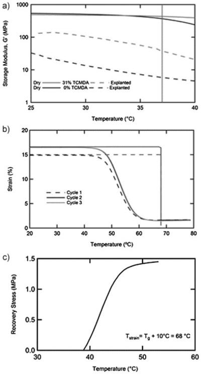
Two thiol–ene/acrylate compositions were selected for characterization as possible substrates for a SMP nerve cuff. The first is the product of the stoichiometric reaction of TATATO, a tri-allyl monomer, and TMICN, a tri-thiol monomer. The second is the product of the stoichiometric reaction of TATATO and TMICN with 31 mol-% TCMDA, a diacrylate, added to raise the glass transition. These monomers were selected based on the precondition that the resulting thermoset polymer shows a distinct and narrow glass transition just above 37 °C. Figure 2a displays the storage modulus in shear for each of these samples. DMA, in the dry state, of these compositions indicates that the onset of glass transition is just below physiological temperatures for the thiol–ene sample and just above physiological temperatures for the thiol–ene/acrylate sample. Each of these compositions was implanted subcutaneously for 1 week and subsequently retested. A significant softening was observed for each composition. While both samples were largely glassy at 37 °C, while dry before implantation, the thiol–ene samples softened to 6 MPa and the thiol–ene/acrylate samples softened to 38 MPa after explantation. While this substrate is still more than an order of magnitude stiffer than tissue found in the peripheral nervous system, this reduction of the modulus mismatch could greatly reduce strains induced in the tissue. Softening can be attributed to the plasticization of the sample due to small amounts of fluid uptake (≈3%). It should be noted that significant fluid uptake can compromise the primary function of the polymer substrate as an insulator, but that 3% fluid uptake is similar to that of many substrates currently used in neural interfaces.[36] Basic biocompatibility of the thiol–ene substrate has been previously demonstrated by the successful culture of osteoblasts.[37] Evaluating biocompatibility of a stimulating electrode array is a complex task requiring extensive studies on the substrate, device and stimulating parameters. After 1 week of implantation the tissue immediately surrounding the site of the polymer disks showed no visible inflammation. In future studies, final device dimensions and the pressure exerted on the nerve by recovery and the swelling of the substrate must be carefully characterized.
Figure 2.
Dynamic mechanical analysis of the thiol–ene and thiol–ene/acrylate compositions both before and after implantation subcutaneously (a). Shape memory behavior of the thiol–ene/acrylate composition was demonstrated through cyclic free strain recovery (b) and constrained recovery (c).
Cyclic free strain and constrained recovery tests demonstrate the utility of this chosen system as a SMP. For the free strain recovery in Figure 2b the sample was first strained in tension to 15% at 68 °C (Tg + 10 °C), cooled under fixed deformation, released at 20 °C and then heated to 80 °C. Shape fixity at 20 °C was <99%. Shape recovery of 89% is observed on the first cycle. On subsequent cycles the sample is strained to a further 15% from the final recovered length at the end of the first cycle. Near 100% recovery is observed on both the second and third cycle. This behavior is typical of network polymers of intermediate crosslink density. Highly repeatable behavior is observed on both the second and third cycles suggesting that under the straining conditions tested, no significant damage or permanent deformation occurs. Constrained recovery, Figure 2c, also indicates a rapid evolution of stress beginning immediately above 37 °C. Understanding the degree of softening and the conditions under which the recovery of the nerve cuff will occur is necessary in the design of a device capable of conforming to, but not damaging, the nerve after implantation.
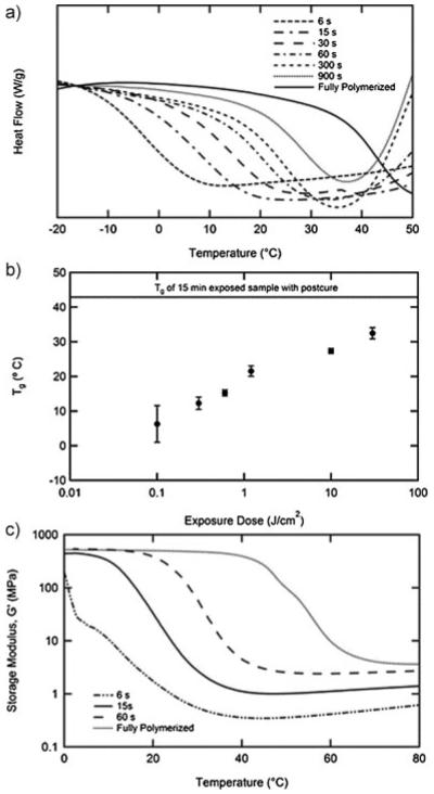
Electrodes are patterned on a planar sacrificial substrate and subsequently able to be transferred to a partially polymerized SMP substrate. This is achieved by creating a mold using the sacrificial substrate as the bottom of the mold. This partially polymerized film can subsequently be removed from the planar mold, be deformed and store another shape which is permanently set through the formation of further crosslinks. After the final device fabrication steps are complete, the shape memory effect can be utilized to deform the device away from the permanent shape and subsequently recover this complex shape in response to physiological conditions. This process utilizes temporal control of the polymerization reaction to partially polymerize the substrate into the planar state only the sufficient amount to transfer the gold electrodes from the underlying glass. Understanding of the evolution of the film properties during the reaction was obtained using DSC and DMA. Figure 3a shows the DSC thermograms for the thiol–ene/acrylate at various exposure times between 6 s and full polymerization which includes 15 min exposure and a post-cure. Each sample shows a distinct step in the heat capacity indicative of a glass transition. All partially polymerized samples also exhibit the onset of an exothermic peak above the glass transition as the reaction restarts due to heating. Figure 3b plots the average midpoint of the transition as a function of exposure dose for four samples. It should be noted that even after as little as 6 s an elastomeric film has formed. A few selected compositions were characterized by DMA in Figure 3c. The relationship between exposure dose and Tg is confirmed by DMA, but importantly the crosslink density of the sample can be quantified throughout the reaction. Rubbery modulus (Gr) is well known to be directly proportional to crosslink density. Gr for the sample polymerized for only 6 s is 0.35 MPa, while for the fully polymerized sample Gr is 3.6 MPa. It is this difference in crosslink density that allows for permanently “fixing” a shape different from the planar state in which the sample gels. Control over the degree of reaction in thiol–ene SMPs has previously been reported as a mechanism to produce “functionally graded” polymers. While the end goal is quite different, the idea of utilizing a thiol–ene polymer in its partially polymerized state is key in both applications.[38] The specified polymer system contains a degree of crosslinking high enough to enable sufficient mechanical rigidity and toughness in partially cured states for sample handling, transfer and reshaping.
Figure 3.
Differential scanning calorimetry of thiol–ene/acrylate composition stopped at different reaction times during the reaction (a). The midpoint of the glass transition from DSC at various stages in the reaction (n = 4, error bars represent standard deviation) (b). DMA of select partially polymerized films (c).
The ability of the post-gelation crosslinks to fix a new globally stable shape is quantified in Figure 4a. The shape recovery ratio is measured by bending a polymer film around a radius of 1 mm similar to the size needed to wrap around the vagus nerve of a rat. The polymerization and post-cure is then completed in this deformed state. Shape recovery to the new globally stable shape is then quantified by measuring the angle with an optical microscope between the two sides of the film after allowing the film to recover in an oven at 75 °C for 10 min. While the recovery of the polymer film begins just below 37 °C, 75 °C was chosen to ensure complete recovery of the device over a few minutes. Shape recovery is then presented as a ratio of the measured angle to the deformed state (1808). Utilizing Gr from Figure 3c, shape recovery towards the new globally stable shape shows an inverse proportional dependence on the ratio of the pre-deformation crosslink density to the fully polymerized crosslink density. The shape recovery after deformation to the planar state at 75 °C and subsequent recovery also indicates the same trend. Samples that were fully polymerized prior to deformation showed no capacity to recover a new globally stable shape, as is expected.
Figure 4.
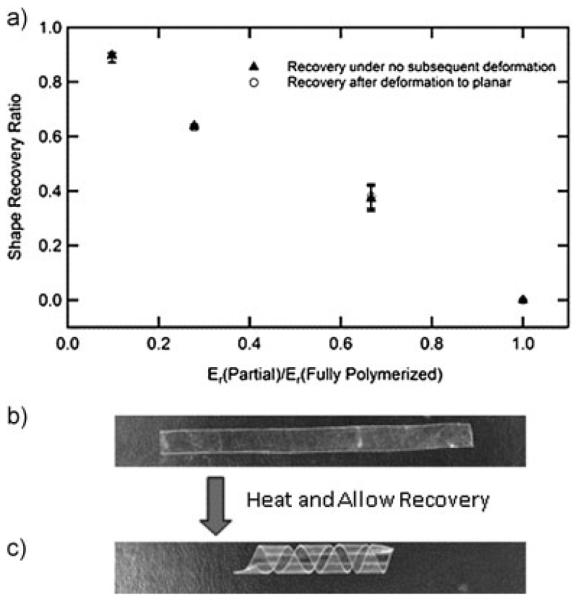
Shape recovery ratio after final curing and after subsequent deformation with various initial reaction times (n = 3, error bars represent standard deviation) (a). A polymer strip was partially polymerized into a planar form, deformed into a helix, and the polymerization was completed. After complete polymerization the helix was heated and flattened (b). Upon heating the strip recovers to a helix (c)
Figure 4b and c demonstrates visually and simply the ability to store and recover an arbitrary shape through the partial polymerization process. A partially polymerized planar film (6 s initial polymerization time) is wrapped around a glass rod (5 mm diameter) into a helix and the polymerization is completed. After removing the film from the rod it is heated and deformed to a planar state. Upon cooling, this metastable shape is fixed at room temperature by the vitrification of the polymer, Figure 4b. The film recovers the helical shape after heating again above the glass transition (Figure 4c). This model system gives a small indication of the potential to simultaneously mimic complex 3D structures, on both the macro and microscale after the transfer of planar electronics, found in the body or otherwise.
3.2. Device Fabrication, Characterization, and Implantation
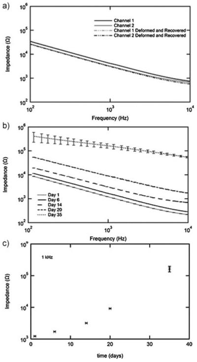
The ability of the described partial-polymerization process to produce an electrically functional nerve cuff is demonstrated in Figure 5. Impedance spectroscopy of a representative cuff both in the “as fabricated” bent shape (1 mm bending radius at the active end of the device) and after one shape memory cycle is shown in Figure 5a. There is no measurable difference in the impedance as a function of frequency on either channel before or after the shape memory cycle. There is, however, a small difference between the two channels shown, most likely due to slight imprecisions in the shadow masking method used. This however does not interfere with the ability to fabricate a functional prototype device. Future work utilizing full photolithography promises to greatly reduce or completely eliminate such issues. The response of cuff electrodes to simulated implantation over 35 d is shown in Figure 5b. AC impedance at the physiologically relevant frequency of 1 kHz increases from 1.2 to 125 kΩ over the testing period, Figure 5c. Generally cuff electrodes for stimulation have impedances on the order of 1–10 kΩ. The observed increase in impedance after several weeks may be to contamination of the electrode surface. Visual inspection of the electrodes was unable to identify the changes in the device. Understanding the electrical behavior of these 3D electrodes over many stimulation cycles is a topic of ongoing investigation. It is notable, however, that despite mechanical deformation, the gold electrodes adhere well to thiol–ene/acrylate substrates and remain continuous on all traces over the 35 d in simulated physiological conditions without an adhesion layer. This adhesion can be attributed to the presence of free thiols and thioether linkages which are known to adhere strongly to gold.
Figure 5.
Impedance spectroscopy (IS) of nerve cuff electrodes fabricated by the partial polymerization process. IS of a representative nerve cuff both before and after a shape memory cycle (a). IS of electrodes (n = 6, error bars represent standard deviation) in simulated physiological conditions over 1 month (b). IS over time at the physiologically relevant frequency of 1 kHz (n = 6, error bars represent standard deviation).
The fabricated nerve cuff is pictured coiled around the vagus nerve of a rat, Figure 6a, and the full device connected to the stimulation cable and around the nerve Figure 6b. While vagus nerve stimulation is the subject of intense investigation for the treatment of numerous neurological disorders there are also several known side effects to this treatment.[11] Specifically, vagus nerve stimulation is known to depress both heart rate and as a result O2 saturation in arterial blood. To demonstrate the cuff’s ability to stimulate the vagus nerve, both of these parameters were monitored during vagus nerve stimulation. Figure 6c shows a statistically significant drop in both heart rate and O2 saturation immediately following stimulation. A set of ten 0.4 mA biphasic pulse trains repeated ten times did not lead to failure of the device and continued to elicit the expected physiological response.
Figure 6.
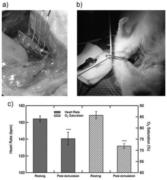
Photographs of the nerve cuff implanted in an anesthetized rat around the vagus nerve (a,b). Effect of vagus nerve stimulation on both heart rate and oxygen saturation in the blood (c). Error bars are a 95% confidence interval; p-values < 0.0001 (t-test, two tails) for both heart rate and O2 saturation.
Gold is not considered an ideal material for stimulating electrodes. This is due to its reduced charge injection capacity as compared to commonly used materials such as platinum. However, the relatively large electrodes used in this study led to a charge density of 6.4 μC · cm−2, well below the safe limit for gold.[39] In future devices, that perhaps require electrodes of much smaller dimensions, materials with a larger charge injection capacity than gold, such as platinum or iridium, can be used to ensure that thousands of stimulation cycles are possible. In addition, nanostructured electrode surfacing, using patterning techniques or other electrode materials such as carbon nanotubes, will lead to enhanced electrode surface area without a corresponding increase in device size, further enhancing charge injection capabilities and device performance. This presents an interesting area for future study in device lifetimes of nanostructured electrodes for both recording and stimulation. However, it should be noted that even as these actively softening, deforming devices begin to incorporate other electrode materials, gold can continue to be used as the conductor. This will allow future devices to utilize the ductile nature of gold and good adhesion to the thiol–ene substrate.
The nerve cuff fabricated using the thiol–ene/acrylate substrates is an example of a softening neural interface capable of actively recovering to more closely conform to the tissue. Temporal understanding of the polymerization of the select thiol–ene/acrylate allows for deformation of a substrate from a planar state in order to determine the final globally stable shape. Future work will apply the described partial-polymerization technique to the fields of neural interfaces and more broadly flexible electronics. While the minimum feature size of 125 μm is quite large compared to devices made by photolithography, through the transfer-by-polymerization technique described here and previously, further improvements are expected. Shadow-masked nerve cuff electrodes represent the first proof-of-concept of implantable, softening neural interfaces fabricated to adapt to a physiological environment utilizing the shape memory effect in a processing paradigm compatible with planar processing for flexible electronics.
4. Conclusion
Advancements in neural interfaces stand to revolutionize the way neuroscientists study the brain and how neurological disorders are diagnosed and treated. Mechanical and geometrical mismatch at the biotic–abiotic interface leads to an aggravated foreign body response and the eventual failure of these devices. This work demonstrates a nerve cuff capable of responding actively to physiological conditions to reduce the mechanical mismatch, by softening two orders of magnitude, and changing shape, to allow for easy insertion and subsequent conformation around the vagus nerve of a rat. Stimulation of the vagus nerve was demonstrated through a marked decrease in heart rate and arterial oxygen saturation. As advanced electronics devices are fabricated with increasingly small feature sizes using photolithography in the micron width regime, the ability to have intelligent polymer systems capable of moving between precise shapes will continue to drive new innovation and technology in electronics, sensing systems, and novel biomedical device technologies.
Acknowledgements
This material is partially based upon work supported from several sources: the National Institutes of Neurological Disorders and Stroke 5R01DC008982; the National Science Foundation Partnerships for Innovation and Graduate Research Fellowship under Grant nos. 1114211 and 2011113646; FUSION support from the State of Texas.
References
- [1].Grill WM, Norman SE, Bellamkonda RV. Annu. Rev. Biomed. Eng. 2009;11:1. doi: 10.1146/annurev-bioeng-061008-124927. [DOI] [PubMed] [Google Scholar]
- [2].Cogan SF. Annu. Rev. Biomed. Eng. 2008;10:275. doi: 10.1146/annurev.bioeng.10.061807.160518. [DOI] [PubMed] [Google Scholar]
- [3].Rennaker R, Voit W, Hutchens C. Society for Neuro-science. New Orleans, LA: 2011. Wireless Distributed Neural Interface System. [Google Scholar]
- [4].Vetter RJ, Williams JC, Hetke JF, Nunamaker EA, Kipke DR. Biomed. Eng., IEEE Trans. 2004;51:896. doi: 10.1109/TBME.2004.826680. [DOI] [PubMed] [Google Scholar]
- [5].Seymour JP, Langhals NB, Anderson DJ, Kipke DR. Biomed. Microdev. 2011;13:1. doi: 10.1007/s10544-011-9512-z. [DOI] [PMC free article] [PubMed] [Google Scholar]
- [6].Polikov V, Tresco P, Reichert W. J. Neurosci. Methods. 2005;148:1. doi: 10.1016/j.jneumeth.2005.08.015. [DOI] [PubMed] [Google Scholar]
- [7].Thelin J, Jörntell H, Psouni E, Garwicz M, Schouenborg J, Danielsen N, Linsmeier CE. PLoS ONE. 2011;6:e16267. doi: 10.1371/journal.pone.0016267. [DOI] [PMC free article] [PubMed] [Google Scholar]
- [8].Ceballos D, Valero A, Valderrama E, Stieglitz T, Navarro X. J. Neurosci. Methods. 2000;98:105. doi: 10.1016/s0165-0270(00)00192-8. [DOI] [PubMed] [Google Scholar]
- [9].Minev IR, Chew DJ, Delivopoulos E, Fawcett JW, Lacour SP. J. Neural Eng. 2012;9:026005. doi: 10.1088/1741-2560/9/2/026005. [DOI] [PubMed] [Google Scholar]
- [10].Shetake JA, Engineer ND, Vrana WA, Wolf JT, Kilgard MP. Exp. Neurol. 2012;233:342. doi: 10.1016/j.expneurol.2011.10.026. [DOI] [PubMed] [Google Scholar]
- [11].Porter BA, Khodaparast N, Fayyaz T, Cheung RJ, Ahmed SS, Vrana WA, Rennaker RL, II, Kilgard MP. Cereb. Cortex. 2012;22:2365. doi: 10.1093/cercor/bhr316. [DOI] [PubMed] [Google Scholar]
- [12].Hassler C, Boretius T, Stieglitz T. J. Polym. Sci. Part B: Polym. Phys. 2011;49:18. [Google Scholar]
- [13].Rousche PJ, Pellinen DS, Pivin DP, Jr., Williams JC, Vetter RJ. Biomed. Eng., IEEE Trans. 2001;48:361. doi: 10.1109/10.914800. [DOI] [PubMed] [Google Scholar]
- [14].Borschel GH, Kia KF, Kuzon WM, Jr., Dennis RG. J. Surg. Res. 2003;114:133. doi: 10.1016/s0022-4804(03)00255-5. [DOI] [PubMed] [Google Scholar]
- [15].Lacour SP, Wagner S, Huang Z, Suo Z. Appl. Phys. Lett. 2003;82:2404. [Google Scholar]
- [16].Korivi NS, Ajmera PK. Sens. Actuators B: Chem. 2011;160:1514. [Google Scholar]
- [17].Crampon MA, Brailovski V, Sawan M, Trochu F. Bio-Med. Mater. Eng. 2002;12:397. [PubMed] [Google Scholar]
- [18].Crampon M-A, Sawan M, Brailovski V, Trochu F. Artif. Organs. 1999;23:392. doi: 10.1046/j.1525-1594.1999.06357.x. [DOI] [PubMed] [Google Scholar]
- [19].Ware T, Simon D, Arreaga-Salas DE, Reeder J, Rennaker R, Keefer EW, Voit W. Adv. Funct. Mater. 2012;22:3470. [Google Scholar]
- [20].Harris JP, Hess AE, Rowan SJ, Weder C, Zorman CA, Tyler DJ, Capadona JR. J. Neural Eng. 2011;8:046010. doi: 10.1088/1741-2560/8/4/046010. [DOI] [PMC free article] [PubMed] [Google Scholar]
- [21].Harris JP, Capadona JR, Miller RH, Healy BC, Shanmuganathan K, Rowan SJ, Weder C, Tyler DJ. J. Neural Eng. 2011;8:066011. doi: 10.1088/1741-2560/8/6/066011. [DOI] [PMC free article] [PubMed] [Google Scholar]
- [22].Hess A, Dunning J, Harris J, Capadona JR, Shanmuganathan K, Rowan SJ, Weder C, Tyler DJ, Zorman CA. A bio-inspired, chemo-responsive polymer nanocomposite for mechanically dynamic microsystems; Solid-State Sensors, Actuators and Microsystems Conference, 2009. Transducers 2009. International; Jun 21–25, 2009. [Google Scholar]
- [23].Lendlein A, Langer R. Science. 2002;296:1673. doi: 10.1126/science.1066102. [DOI] [PubMed] [Google Scholar]
- [24].Feninat FE, Laroche G, Fiset M, Mantovani D. Adv. Eng. Mater. 2002;4:91. [Google Scholar]
- [25].Baer TSWG, Matthews DL, Maitland DJ. J. Appl. Polym. Sci. 2007;103:3882. [Google Scholar]
- [26].Mather P, Luo X, Rousseau I. Annu. Rev. Mater. Res. 2009;39:445. [Google Scholar]
- [27].Voit W, Ware T, Dasari RR, Smith P, Danz L, Simon D, Barlow S, Marder SR, Gall K. Adv. Funct. Mater. 2010;20:162. [Google Scholar]
- [28].Voit W, Ware T, Gall K. Polymer. 2010;51:3551. [Google Scholar]
- [29].Hearon K, Gall K, Ware T, Maitland DJ, Bearinger JP, Wilson TS. J. Appl. Polym. Sci. 2011;121:144. doi: 10.1002/app.33428. [DOI] [PMC free article] [PubMed] [Google Scholar]
- [30].Hoyle CE, Lowe AB, Bowman CN. Chem. Soc. Rev. 2010;39:1355. doi: 10.1039/b901979k. [DOI] [PubMed] [Google Scholar]
- [31].Kade MJ, Burke DJ, Hawker CJ. J. Polym. Sci. Part A: Polym. Chem. 2010;48:743. [Google Scholar]
- [32].Carioscia JA, Schneidewind L, O’Brien C, Ely R, Feeser C, Cramer N, Bowman CN. J. Polym. Sci. Part A: Polym. Chem. 2007;45:5686. [Google Scholar]
- [33].Wei H, Senyurt AF, Jönsson S, Hoyle CE. J. Polym. Sci. Part A: Polym. Chem. 2007;45:822. [Google Scholar]
- [34].Senyurt AF, Wei H, Hoyle CE, Piland SG, Gould TE. Macromolecules. 2007;40:4901. [Google Scholar]
- [35].Engineer ND, Riley JR, Seale JD, Vrana WA, Shetake JA, Sudanagunta SP, Borland MS, Kilgard MP. Nature. 2011;470:101. doi: 10.1038/nature09656. [DOI] [PMC free article] [PubMed] [Google Scholar]
- [36].Rubehn B, Stieglitz T. Biomaterials. 2010;31:3449. doi: 10.1016/j.biomaterials.2010.01.053. [DOI] [PubMed] [Google Scholar]
- [37].Nordberg A, Antoni P, Montañez MI, Hult A, Von Holst H, Malkoch M. ACS Appl. Mater. Interfaces. 2010;2:654. doi: 10.1021/am100002s. [DOI] [PubMed] [Google Scholar]
- [38].DiOrio AM, Luo X, Lee KM, Mather PT. Soft Matter. 2011;7:68. [Google Scholar]
- [39].Hung A, Goldberg IB, Judy JW, Zhou D, Greenbaum E, editors. Stimulation Electrode Materials and Electrochemical Testing Methods. Springer; New York: 2010. Implantable Neural Prostheses 2; p. 191. [Google Scholar]


