Abstract
Corner cube retroreflectors are objects with three mutually perpendicular reflective surfaces that return light directly to its source and are therefore extremely bright and easy to detect. In this work, we have fabricated suspended corner cube retroreflectors, 5 microns in size, consisting of a transparent epoxy core and three surfaces coated with gold as ultra-bright labels for use in a rapid, low-labor diagnostic platform. The authors have demonstrated that individual cubes are easily imaged using low-cost, low numerical aperture objectives in suspension and that they remain suspended over long periods of time. Moreover, we have demonstrated that the gold outer surfaces can be decorated with proteins, and that individual cubes can be bound to magnetic sample preparation particles bearing antibodies which recognize these proteins. The bound cubes can be imaged and tracked as they move through solution in response to an external magnetic field, and we have, as such, demonstrated the principle of the new biosensing approach.
I. INTRODUCTION
Many bioanalytical and diagnostic methods rely upon the use of labels, such as colored particles, fluorescent molecules, nanoparticles, and enzyme reaction products, and observe their accumulation at predetermined sites when the target biomolecules are present.1–6 The accumulation is driven by highly selective molecular binding events, such as DNA hybridization and antigen recognition by antibodies. In this work, we report on our development of a new class of labels consisting of suspended micron-scale corner cube retroreflectors. These transparent cubes have three reflective, mutually perpendicular surfaces, and return light directly to its source over a broad range of angles, making them extremely detectable using simple, low-cost optics. These properties of retroreflectors are widely exploited in traffic markers,7 reflective safety markings, reflective clothing,8 and in lunar ranging measurements.9,10 When compared to other labels, retroreflecting objects can be fabricated to be similar in size and much brighter than dyed particles, can be readily imaged using lower cost optics when compared to fluorescent particles, do not suffer from photobleaching, and can incorporate magnetic films and other elements in the particles themselves.
Micron-scale retroreflecting objects have been previously studied, primarily in the form of reflective sheets containing large arrays of retroreflectors with dimensions of tens to hundreds of microns, and they are typically designed to detect macroscopic objects through the combined effect of the many retroreflectors in the array. Micron-scale corner cube arrays have been fabricated using optical lithography and a moving mask technique which allows patterning of the three dimensional reflector elements directly into the polymer resist.11 Similarly, arrays of corner cubes have been formed using direct write laser lithography by calibrating the exposure time of the laser to the amount of resist removed.12 Arrays of cat’s eye retroreflectors, consisting of two lenses with differing curvatures, have been formed in polymer sheets using advanced microfabrication techniques.13 More recently, suspended pressure sensing particles with a corner cube geometry have been fabricated using a deformable polysilicon membrane.14 Modeling15 work has shown that corner cubes as small as five times the illumination wavelength are not significantly degraded by diffraction. In addition to these arrays, retroreflectors, with hundreds of microns on a side, have been fabricated as passive optical communication devices using MEMS technology. The retroreflected signal is modulated by means of including physically moving one of the corner cube mirrors and using electrically deformable membranes built into one mirror to encode the reflected beam with a data stream.16–18
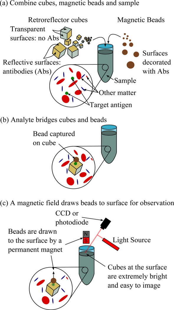
These approaches have worked well for their intended purposes, but none have yielded sub-10 µm, suspended retroreflectors that can be readily combined with biological samples as ultra-bright labels. We are interested in developing this technology as part of a biosensing platform that is shown schematically in Fig. 1. In this approach, in Fig. 1(a) corner cube retroreflectors and magnetic sample preparation particles, both bearing antibodies to the target pathogen, are directly added to a minimally processed patient sample. In Fig. 1(b), the target pathogen, if present, is captured by antibodies on the cubes’ surfaces and bridges the cubes to the particles. For the readout, a magnetic field is applied that draws only magnetic particles to an imaging site in the sample container. In Fig. 1(c), if the retroreflectors are bound to magnetic particles, they are “dragged” to this site where they can be readily detected using inexpensive optics. Cubes that are not bound to magnetic particles simply settle to the bottom of the sample tube and are not imaged. Other work has shown that this approach works well when bridging gold nanoparticles to 1 µm magnetic particles with target DNA and proteins (prostrate specific antigen), although our system is noticeably different in the fact that the cubes and magnetic particles are much bigger.19,20
Fig. 1.
(Color online) Schematic of the proposed “drag assay” for which the micron-scale retroreflectors have been developed.
As a first step toward developing such a “drag” assay, in this work we report on the details of the fabrication of the cubes and demonstrate the ability to image a single cube, bound through antibody coupling to a magnetic sample preparation particle, moving through solution in response to an applied magnetic field.
II. EXPERIMENTAL PROCEDURES
A. Cube fabrication
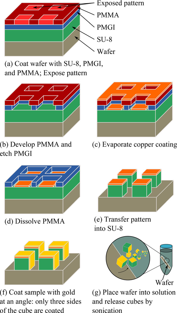
The cube fabrication sequence is shown schematically in Fig. 2. Figure 2(a) shows a five micron thick layer of SU-8 5 photoresist (Microchem, Inc., Newton, MA) is deposited onto a silicon wafer by spin-casting at 2000 rpm for 1 min, and is baked on a hot plate at 90 °C for 3min. The sample is then exposed to a 254 nm wavelength UV light source (UVP CL-1000, Upton, CA) and baked at 90 °C for 3 min to cure the epoxy-based resist. A 300 nm layer of poly(methyl glutarimide) (PMGI) (Microchem SF-6) is deposited by spincasting at 2000 rpm for 2min and is annealed at 180 °C for 5 min. This is followed by spin-casting 70 nm of poly(methyl methacrylate) (PMMA) resist, followed by an anneal step at 180 °C for 1 h.
Fig. 2.
(Color online) Schematic of the fabrication sequence for corner cube retroreflectors used in this work.
Next, the retroreflector pattern is printed using a proximity lithography tool described elsewhere.21 In this process, a stencil mask, containing a 1 × 1 cm2 area of 5 µm square openings on a 10 µm pitch in a silicon nitride membrane, is exposed to a broad beam of energetic helium atoms. Particles that strike the opaque regions of the mask are stopped, while those that pass through the openings expose the PMMA resist on the substrate. This high-resolution technique is used here primarily because it is available at our institution; the patterns at these dimensions also could be formed by more traditional lithographic approaches.
Figure 2(b) shows that after patterning, the resist is developed in a 3:1 solution of isopropyl alcohol (IPA) and methyl isobutyl ketone for 30 s, rinsed in IPA for an additional 30 s and dried in nitrogen. The PMGI is then isotropically etched in a 2.3% solution of tetra methyl ammonium hydroxide in water (Microposit MF319 Developer, Shipley Company, Marlborough, MA) for 20 s. The etch time is experimentally determined to remove the full thickness of the PMGI and undercut the PMMA layer without compromising its mechanical stability. This development is performed at room temperature, and is a critical step in ensuring effective lift off later in the fabrication sequence.
As shown in Fig. 2(c), a thin layer of copper is evaporated onto the substrate and coats both the PMMA and the base of the patterned openings. Copper was chosen because it is readily evaporated with good collimation using a simple thermal evaporator, has good etch selectivity to SU-8 in oxygen reactive ion etching, and is nonmagnetic. In Fig. 2(d), the PMMA is dissolved in an acetone bath, leaving behind square copper patches. In Fig. 2(e), an in-house, magnetically- enhanced reactive ion etch process21 using oxygen transfers the pattern into the SU-8, leaving a cube structure. For this process, 1 mTorr of O2 is introduced into a chamber with a base pressure of 5 × 10⁻⁷ mTorr. A 5-in. electrode is driven with a 13.56 MHz RF signal at 50W in the presence of a 50G axial magnetic field, yielding an SU-8 etch rate of approximately 70 nm/min and a copper selectivity of >100:1, so that 120 nm of copper is sufficient for a 200% overetch. In Fig 2(f), a 10 nm thick titanium layer and a 100 nm gold layer are evaporated at an angle relative to the surface normal so that only three of the optically transparent SU-8 surfaces are coated.
Finally, as shown in Fig 2(g), the cubes are released by submerging the wafer into a beaker of water and then placing this into an ultrasonic bath (Cole-Parmer Instrument Company, Vernon Hills, IL).
B. Surface functionalization
After suspending 1 × 10⁷ cubes in 1mL of water, the pH was adjusted to 9.0 with 1M NaOH and mouse IgG (anti lysozyme antibody HyHEL-5) was added at a concentration of 1.5 mg/mL. The particles were incubated with constant gentle mixing on a Cole-Parmer Rototorque (Cole-Parmer Instrument Company, Vernon Hills, IL) gyratory rotator for 2 h at room temperature.19 The particles were then pelleted at 5000×g for 5min and then re-suspended in 1mL of 2% bovine serum albumin for overnight passivation at room temperature with constant gentle mixing on the rotator. After the overnight incubation, the particles were washed 3 times with 1 × phosphate buffered saline (PBS) (1 mL) and finally re-suspended in 200 µL 1 × PBS. Meanwhile, 3 µm ProMag PMC3N COOH magnetic particles were functionalized with polyclonal anti-mouse IgG (M8645, Sigma-Aldrich, St. Louis, MO) antibodies (3 × 10⁸ particles/mL).
C. Imaging
We image the retroreflectors in solution using an InfiniTube-FM lenses (Infinity Photo-optical, Boulder, CO) with 8× magnification and 0.1 numerical aperture, a USB controlled CMOS camera (Model 5012 M, Edmund Optics, Barrington, NJ), a halogen incandescent light source, a fiber optic light guide, and a boom stand.
III. RESULTS AND DISCUSSION
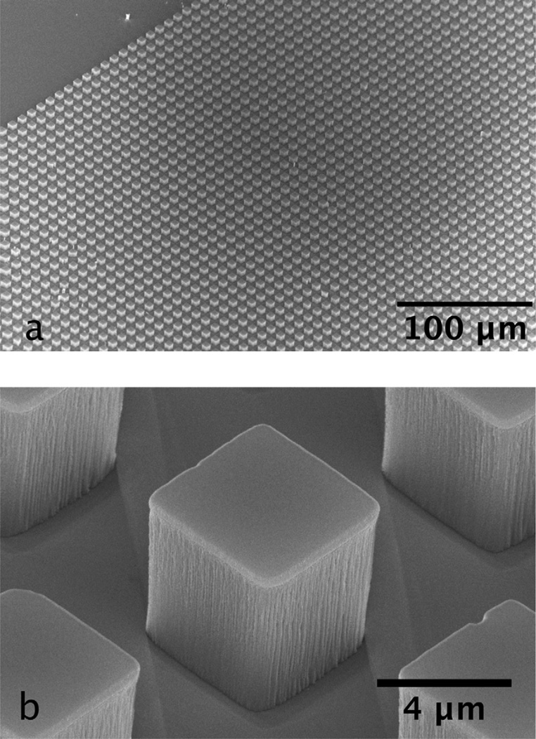
Figure 3(a) shows a birds-eye view and Fig. 3(b) shows close-up scanning electron microscope (SEM) images of 5 µm corner cubes on a silicon wafer surface prior to release imaged at an angle of 45°. In Fig. 3(b), the shadows cast during the angled evaporation step [i.e., Fig. 2(f)] are visible so that the two front surfaces in this image consist of a transparent polymer, with the top and back two surfaces coated with gold. The RIE step [Fig. 2(e)] is sufficient to transfer the pattern through the full 5 µm polymer, although the etch does leave visible striations in cube surfaces. Our experience is that these are not substantial enough to degrade the reflectivity of the surface. The cube density for this pattern is about 106/cm2, and the 1 cm2 mask is copied in about 20 s. Other lithographic approaches may have higher throughput, and ours could be increased, however this throughput is sufficiently high for laboratory-scale manufacturing since we expect to use less than 105 cubes in a 1 mL assay.
Fig. 3.
Scanning electron micrographs of corner cube retroreflectors.
Because the dimensions of the cubes are rather large, other manufacturing approaches could also be employed to form the cubes, including forming the transparent material in resist through a single optical exposure and through embossing22 or injection molding.
The ultrasonic release step initially gave nonrepeatable results, sometimes releasing all cubes over a short period, and at other times releasing none, even after several hours of sonication. During the optimization of this step, we did note that it is important that the sample be oriented parallel to the liquid surface when placing the sample in the bath. We assume that the pressure waves in this orientation are parallel to the wafer surface and provide sufficient shear force to remove the cubes. We also note that the water level in the bath plays an important role and that the water level has to be adjusted until the particles begin to release. When this step is working properly, the release occurs in small bursts at random intervals where square centimeter-sized regions are spontaneously removed from the wafer. The typical time needed to complete this step is approximately half an hour. We expect that the release of the particles can be further optimized, preferably by using a sacrificial release layer that can simply be dissolved. The fact that the gold bridges the cube to the wafer and has to break along the edge further complicates this step; an undercut release layer could be used to avoid the bridging and is being explored as an alternative manufacturing approach.
Once released from the wafer, the cubes remain suspended in water and slowly settle to the bottom of the container over a period of a few hours. When the sample container is shaken, they again re-suspend without any observable residue at the base of the container, and they remain re-suspendable over a period of at least six months, the longest period for which we stored our samples. When the cubes are imaged using our microscope, they appear extremely bright, as can be seen in the optical microscope image in Fig. 4(a). The bright white spots are cubes in the focal plane, which is about 30 µm deep, and we observe them drifting through this volume as they settle at the base of the sample holder. The hazy objects are images of cubes as they move out of the focal plane and they completely disappear as the particles drift further down the sample tube. The orientation of the cubes relative to the microscope determines how bright they will appear. We observe, by saturating the image, that cubes that are not properly oriented appear to be extremely dim, similar to the scattering signal from the spherical magnetic particles. When the brightness of the image is adjusted to ensure that the retroreflecting cubes are not saturated, the scattered signal is no longer visible.
Fig. 4.
Retroreflecting corner-cubes imaged (a) in solution, and (b) at fixed locations on a silicon wafer using an 8×, 0.1NA optical microscope.
In Fig. 4(b), we show images of cubelike structures on a silicon wafer and images without releasing the particles. The structures are chevron-shaped, as can be seen in the inset, with the three mutually perpendicular walls of the retroreflector formed by the base and two of the side walls. They resemble the suspended cubes, except that there is no transparent polymer (i.e., they are like cubes where the polymer has been removed) and we can use these structures to determine the brightness as a function of the cube orientation and to calibrate the images of cubes in solution. By comparing the two images we conclude that the bright spots are, in fact, due to retroreflecting cubes; that they are the brightest objects visible in solution; and they are therefore ideally suited for the proposed assay. These chevrons are imaged from the optimal orientation and therefore appear at their largest. When viewed from different directions, they appear to be smaller, allowing us to recreate the range of sizes that appear in images of suspended cubes.
Other geometries, including spherical and cat’s-eye reflectors, could be used in place of the corner cube design to created suspended particles. Since these implementations use refraction to focus the light, their geometry and composition will have to be tailored for use in an aqueous environment, and their use will be limited to liquids with a small range of index of refraction. The spherical design will place stringent limits on the choice of transparent materials that have a sufficiently high index of refraction, while the cat’s-eye design is complex to manufacture since it requires two aligned lenslets with different focal lengths. Furthermore spherical microbead retroreflectors have been shown to suffer from highly angular retroreflectance, requiring higher numerical aperture optics to collect more of the retroreflected light.23
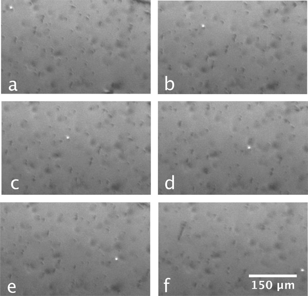
Our first evidence of particles bridging to retroreflectors is shown in the six video frames shown in Fig. 5. Here, a solution containing retroreflectors and magnetic particles (both treated as outlined before) has been dispensed into a 100 µm thick channel created between two glass slides. We were able to observe a single retroreflector (the bright spot in the images) move over a few millimeters in response to an external magnetic field. The cube concentration in this experiment was extremely low to better simulate the detection of low-concentration pathogens, and shows that the nonmagnetic cubes have been bound to the magnetic particles and can be “dragged” into an imaging area within the sample.
Fig. 5.
From the top left to the bottom right, the retroreflector cube (bright spot) and magnetic particles (dark spots) move in response to the presence of an external magnet. The time elapsed between frames is 1 s.
For this experiment, we do not know the details of the antibody surface coverage on the beads and on the cubes, nor do we know how many antigen-antibody interactions hold the cube and bead together. These details are important in designing an assay, and particular attention needs to be placed on the bond strength, which we expect needs to be higher than that used for more traditional molecular labeling approaches. However, this requirement for stronger binding strength may be used as an advantage to reduce nonspecific interactions that often lead to false positives. The requirements on antibody-antigen interaction will need to be studied further as assays are developed.
IV. SUMMARY
We have developed a process for fabricating suspended corner cube retroreflectors using standard lithographic, thinfilm deposition, and reactive ion etching techniques. We have released these particles into solution and have demonstrated that they are stable and extremely easy to image using low-cost optics. We have functionalized these particles with antibodies and demonstrated that cubes can be bound to magnetic sample preparation particles containing antibodies that recognize the antibodies on the cube surface and can dragged over long distances with an applied magnetic field. The cubes remain easy to detect and image as they move over more than 1mm, and this ability could be the basis of a new biosensing platform.
ACKNOWLEDGMENTS
The project described was supported by Grant No. U54 AI057156 from NIAID/NIH. Its contents are solely the responsibility of the authors and do not necessarily represent the official views of the RCE Programs Office, NIAID, or NIH. Support was also provided by the National Science Foundation, Grant No. CMMI-0900743, the Alliance for Nanohealth Competitive Research Program (Grant No. W81XWH-09-2-0139), and the Welch Foundation, Grant No. E-1264. We also thank the students who participated in developing this project through the NSF Research Experience for Undergraduates program and the University of Houston (Project No. EEC-0647775), especially Ward Jablonski, Jon Elizalde, and David Shakarisaz. The authors thank the Center for Integrated Bio and Nanosystems and the University of Houston Nanofabrication Facility for providing excellent facilities and support.
Contributor Information
Tim Sherlock, Department of Electrical and Computer Engineering, University of Houston, Houston, Texas 77004.
Azeem Nasrullah, Department of Electrical and Computer Engineering, University of Houston, Houston, Texas 77004.
Julia Litvinov, Department of Biomedical Engineering, University of Houston, Houston, Texas 77004.
Eliedonna Cacao, Department of Chemical and Biomolecular Engineering, University of Houston, Houston, Texas 77004.
Jennifer Knoop, Department of Chemical and Biomolecular Engineering, University of Houston, Houston, Texas 77004.
Steven Kemper, Department of Chemical and Biomolecular Engineering, University of Houston, Houston, Texas 77004.
Katerina Kourentzi, Department of Chemical and Biomolecular Engineering, University of Houston, Houston, Texas 77004.
Archana Kar, Department of Chemical and Biomolecular Engineering, University of Houston, Houston, Texas 77004.
Paul Ruchhoeft, Department of Electrical and Computer Engineering and Department of Biomedical Engineering, University of Houston, Houston, Texas 77004.
Richard Willson, Department of Chemical and Biomolecular Engineering and Department of Biology and Biochemistry, University of Houston, Houston, Texas 77004.
References
- 1.Vikesland PJ, Wigginton KR. Environ. Sci. Technol. 2010;44:3656. doi: 10.1021/es903704z. [DOI] [PubMed] [Google Scholar]
- 2.Mohammed MI, Desmulliez MPY. Lab Chip. 2011;11:569. doi: 10.1039/c0lc00204f. [DOI] [PubMed] [Google Scholar]
- 3.Song S, Qin Y, He Y, Huang Q, Fan C, Chen HY. Chem. Soc. Rev. 2010;39:4234. doi: 10.1039/c000682n. [DOI] [PubMed] [Google Scholar]
- 4.Rissin DM, Kan CW, Campbell TG, Howes SC, Fournier DR, Song L, Piech T, Patel PP, Chang L, Rivnak AJ. Nat. Biotechnol. 2010;28:595–595. doi: 10.1038/nbt.1641. [DOI] [PMC free article] [PubMed] [Google Scholar]
- 5.Quach AD, Crivat G, Tarr MA, Rosenzweig Z. J. Am. Chem. Soc. 2011;133:2028. doi: 10.1021/ja109348d. [DOI] [PubMed] [Google Scholar]
- 6.Hartwell SK, Grudpan K. Microchim. Acta. 2010;169:201. [Google Scholar]
- 7.Hawkins HG, Carlson PJ. Transp. Res. Rec. 2001;1754:11. [Google Scholar]
- 8.Luoma J, Schumann J, Traube EC. Accid. Anal. Prev. 1996;28:377. doi: 10.1016/0001-4575(96)00004-8. [DOI] [PubMed] [Google Scholar]
- 9.Poultney SK, Alley CO, Dicke RH, Wilkinson DT, Eckhardt DH, Faller JE, Kaula WM, Bender PL, Currie DG, Mulholland JD. Science. 1973;182:229. doi: 10.1126/science.182.4109.229. [DOI] [PubMed] [Google Scholar]
- 10.Dickey JO, Bender PL, Faller JE, Newhall XX, Ricklefs RL, Ries JG, Shelus PJ, Veillet C, Whipple AL, Wiant JR. Science. 1994;265:482. doi: 10.1126/science.265.5171.482. [DOI] [PubMed] [Google Scholar]
- 11.Yuan J, Chang S, Li S, Zhang Y. Opt. Commun. 2002;209:75. [Google Scholar]
- 12.Lou Y, Wang H, Liu Q, Shi Y, He S. Appl. Opt. 2010;49:5567. doi: 10.1364/AO.49.005567. [DOI] [PubMed] [Google Scholar]
- 13.Lundvall A, Nikolajeff F, Lindstrom T. Opt. Express. 2003;11:2459. doi: 10.1364/oe.11.002459. [DOI] [PubMed] [Google Scholar]
- 14.Chalasani S, Xie Y, Mastrangelo CH. Proceedings of the IEEE 24th International Conference on Micro Electro Mechanical Systems. Vol. 1158. New York: IEEE; 2011. [Google Scholar]
- 15.Ichikawa H. J Opt. A, Pure Appl. Opt. 2004;6:S121. [Google Scholar]
- 16.Achour M. Proc. SPIE. 2004;5614:52. [Google Scholar]
- 17.Zhou L, Kahn JM, Pister KSJ. J. Microelectromech. Syst. 2003;12:233. [Google Scholar]
- 18.Chan TK, Ford JE. J. Lightwave Technol. 2006;24:516. [Google Scholar]
- 19.Nam JM, Thaxton CS, Mirkin CA. Science. 2003;301:1884. doi: 10.1126/science.1088755. [DOI] [PubMed] [Google Scholar]
- 20.Nam JM, Stoeva SI, Mirkin CA. J. Am. Chem. Soc. 2004;126:5932. doi: 10.1021/ja049384+. [DOI] [PubMed] [Google Scholar]
- 21.Nasrullah A, Smith D, Sherlock T, Ruchhoeft P, Litvinov D. J. Vac. Sci. Technol. B. 2009;27:2674. [Google Scholar]
- 22.Rolland JP, Maynor BW, Euliss LE, Exner AE, Denison GM, DeSimone JM. J. Am. Chem. Soc. 2005;127:10096. doi: 10.1021/ja051977c. [DOI] [PubMed] [Google Scholar]
- 23.Seward GH, Cort PS. Opt. Eng. (Bellingham) 1999;38:164. [Google Scholar]


