Abstract
This paper presents novel store-and-forward packet routing algorithms for Wireless Body Area Networks (WBAN) with frequent postural partitioning. A prototype WBAN has been constructed for experimentally characterizing on-body topology disconnections in the presence of ultra short range radio links, unpredictable RF attenuation, and human postural mobility. On-body DTN routing protocols are then developed using a stochastic link cost formulation, capturing multi-scale topological localities in human postural movements. Performance of the proposed protocols are evaluated experimentally and via simulation, and are compared with a number of existing single-copy DTN routing protocols and an on-body packet flooding mechanism that serves as a performance benchmark with delay lower-bound. It is shown that via multi-scale modeling of the spatio-temporal locality of on-body link disconnection patterns, the proposed algorithms can provide better routing performance compared to a number of existing probabilistic, opportunistic, and utility-based DTN routing protocols in the literature.
Keywords: Body area sensor networks, Multi-scale link locality, Probabilistic routing, Utility based routing, Delay tolerant networks
1. Introduction
1.1. Body area networks
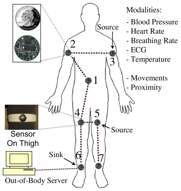
Human health monitoring [1–5] is emerging as a prominent application of the embedded sensor networks [6,7]. A number of tiny wireless sensors, strategically placed or implanted on a patient’s body, can create a Wireless Body Area Network (WBAN) [8,9]. A WBAN can monitor vital signs, providing real-time feedback for enabling many patient diagnostics procedures via continuous monitoring of chronic conditions, or recovery progress from an illness or surgical procedure. Recent technological advances in wireless networking promise a new generation of wireless sensor networks suitable for such on-body networked systems. Data transaction across such sensors can be point-to-point or multipoint-to-point depending on specific applications. While distributed detection of an athlete’s posture [10,11] would require point-to-point data exchange across various on-body sensors, applications such as monitoring vital signs, as shown in Fig. 1, will require all body-mounted and/or implanted sensors [9,12] to route data multipoint-to-point to a sink node, which in turn can relay the information wirelessly to an out-of-body server. Data transaction can be also real-time or non-real-time. While patient monitoring type of applications would require real-time packet routing, monitoring an athlete’s physiological data can be collected offline for post-processing and analysis purposes. The routing protocols designed in this paper cater to this non-real-time class of on-body applications.
Fig. 1.
Body area sensor network.
1.2. Short RF transmission range
In this paper we explore on-body packet routing issues in the presence of topological partitioning caused due to ultra-short wireless range and postural body movements. Short transmission range is a common constraint for low-power RF transceivers designed for embedded applications with limited energy [13,14], often supplied by harvested operations [15]. Such situations are particularly pertinent for implantable body sensors. Examples of ultra-low range transceivers in the literature include [16] with 0–1 m, [15] with 0.2–1 m, [17] with 0.2 m, and [18] with 0–1 m transmission ranges. The corresponding transmission powers vary between 0.75 mW to 6 mW, which are within a range that can be handled with common harvesting techniques such as piezo-electric generation from body movements. Information available in the literature on such low-power RF transceivers is summarized in Table 1.
Table 1.
Low power and short range RF transceivers.
1.3. Routing with network partitioning
Low RF transmission ranges also mean that postural body movements can give rise to frequent partitioning or disconnection in WBAN topologies, resulting in a body area Delay Tolerant Network (DTN) [19–24]. Such topological partitioning can often get aggravated by the unpredictable RF attenuation caused due to signal blockage by clothing material and body segments. Although real-time applications such as patient monitoring may not be supported in the presence of topological partitioning, non-real-time applications such as athlete’s physiology monitoring can still be supported using on-body DTN packet routing across disconnected partitions. Performance goals for such protocols will be to obtain: (1) low end-to-end delay, (2) low packet loss, and (3) low transmission energy consumption.
1.4. Objective and contributions
The goal of this paper is to develop on-body store-and-forward packet routing algorithms in the presence of network partitioning. The objective is to minimize end-to-end packet delays by dynamically choosing routes on which the storage/buffering delays caused due to topological disconnections are low. While ensuring low storage delay, the algorithm also attempts to minimize the end-to-end hop-count so that the transmission energy drainage is minimized, thus leading to long network operating durations. Note that in the absence of network congestions in low data-rate WBANs, the storage delays due to topological disconnections are usually much larger compared to the congestion delay. That is why the congestion delay is not modeled in this paper.
Specific contributions of the paper are as follows. First, we develop a prototype body area network for motivating the on-body packet routing problem and validating the proposed routing algorithm. Second, using the prototype network, we develop detailed topology characterization mechanisms in order to demonstrate the network partitioning caused due to human postural mobility. Third, a probabilistic and a distance vector packet routing frameworks are developed using a stochastic link cost formulation that captures multi-scale topological localities in human postural movements. Fourth, the performance of the proposed protocols are experimentally evaluated using the prototype body sensor network, and are compared with a probabilistic [24], an utility-age based [25,26], and an opportunistic [27] DTN routing protocol from the literature. Finally, an off-line simulation model is developed for validating the experimental performance trends obtained from the prototype WBAN.
2. Related work
Many body area network implementations using on-body sensor communication have recently been reported in the literature [3,8,28,29]. A number of these papers focus mainly on the on-body MAC layer issues. The system in [3] uses a slotted multipoint-to-point architecture in which the data from multiple on-body sensors are sent to a sink node in a collision free manner. The transmission slots are synchronized using beacons periodically sent by a pre-designated sink node. The mechanisms reported in [8] use an on-body adaptation of the standard IEEE 802.15.4/ZigBee based MAC.
The work reported in [28,29] investigate on-body MAC-routing cross-layer issues via distributed transmission coordination in the presence of specific routing structures. In [28], the authors present an energy-efficient slotted MAC in the presence of a Wireless Autonomous Spanning tree Protocol (WASP) that is used for on-body packet routing. The mechanism is cross-layer in that the MAC slot allocation is customized for the underlying routing tree, thus providing routing-specific energy economy at the MAC layer. The protocol in [29] adopts a similar tree-based cross-layer approach, but designed specifically for reducing packet delivery delay over an on-body spanning tree. This protocol also handles body mobility by adaptively re-constructing and maintaining the spanning tree used for packet routing.
From the on-body routing standpoint, most of the existing WBAN systems adopt star or tree topologies on a connected graph; meaning a physically connected end-to-end path between any pair of on-body sensors is assumed at any given point in time. However, these models do not apply for the targeted DTN routing paradigm in this paper, which handles topology partitioning leading to scenarios in which end-to-end physical connectivity between node pairs may not be present at times. Such partitioning is caused mainly due to the ultra short range RF transceivers as reported in Section 1.2.
The existing research on routing in disconnected networks (i.e. Delay Tolerant Networks or DTNs) are categorized [19,20] as: (1) replication based (multiple copy) [21,24,25], (2) knowledge based [22,30], and (3) hybrid of the above two [23,25,30]. The replication approach explores the ways several copies of a packet can be disseminated among several carrier mobile nodes to increase the chance that it would reach the desired destination. While providing good delay performance, the primary limitation of these protocols is their energy and capacity overheads due to excessive packet transmissions. For ultra resource-constrained WBANs, such overheads are not acceptable.
The knowledge based strategies are typically for single copy forwarding and they make use of information about connectivity dynamics to make efficient forwarding decisions [22,30]. The hybrid approaches [23,25,30] combine the replication and knowledge based strategies. The general principle behind these approaches is as follows. When a node with a packet to be forwarded encounters another node, the forwarding rule should determine if the packet (or a copy of the packet) should be transferred to that node or it should be continued to be buffered. The rule is based on the estimate whether the encountered node is more likely than the forwarding node to visit the destination.
For the above mechanisms to work as anything beyond epidemic/viral routing [31], the nodes need to have certain degree of spatial and temporal locality in their mobility and meeting patterns. The scheme PROPHET [24], which is an extension of Epidemic Routing [32], develops a probabilistic framework for capturing the spatio-temporal locality present in the node mobility pattern within a dynamically partitioned wireless network. The authors in [23] define a high-dimensional Euclidean space, called MobySpace, constructed upon nodes’ mobility patterns. The specific MobySpace evaluated is based on the locality of movements defined as the frequency of visits of nodes to each possible location. Node-interaction localities can be also captured in the form a per-link utility as detailed in [25,33]. The link utility can be formulated as its age [26,27,33], formation frequency [33], and other historical parameters that can effectively capture the nodes’ interaction localities.
Two additional routing protocols, namely opportunistic [25,27,33] and randomized [27,33] are also analyzed in the literature for applications in which either there is no node-interaction locality or such localities can not be evaluated. With opportunistic routing, a source node directly delivers its packets to the destination node, and buffers them till the link with the destination is formed. In randomized routing, packets are randomly routed following the hot-potato logic [27]. Both these protocols are hugely outperformed by the locality based protocols [27,33] due to their knowledge about the properties of the links.
The above mechanisms are all applied to networks spanning across local to wide areas, few extending all the way up to the inter-planetary scale [34]. The objective in our work is to apply the key DTN routing concepts, as identified above, in an ultra short-range body area environment. The challenge is to develop mechanisms for capturing the locality of on-body node movements caused by human postural mobility. A key contribution of our work is to formulate mechanisms that capture multi-scale topological localities in human postural movements. Unlike the existing utility-based [25,26,33] and probabilistic [24,32] DTN routing protocols that capture only short-term node-interaction locality, in this work we device mechanisms for capturing movement localities at both short and long terms. Such multi-scale locality is shown to improve the packet routing performance in an on-body context.
3. Characterization of on-body network topology
This section presents an experimental characterization of WBAN network topology with different postural positions.
3.1. Experimental settings
In our laboratory, a Wireless Body Area Network (WBAN) is constructed by mounting seven sensor nodes (attached on two upper-arms, two thighs, two ankles and one in the waist area) as shown in Fig. 1. Each wearable node consists of a 900 MHz Mica2Dot MOTE (running Tiny-OS operating system), with Chipcon’s SmartRF CC1000 radio chip (chipcon.com), and the sensor card MTS510 from Crossbow Inc. (xbow.com). The Mica2Dot nodes run from a 570 m AH button cell with a total sensor weight of approximately 10 g. The default CSMA MAC protocol is used with a data rate of 19.2 kbps.
Via software adjustments of the CC1000’s transmission power, the transmission range is set to be in between 0.3 m and 0.6 m. By doing so, we are able to emulate the ultra-low transmission range for the embedded transceivers [15–18] as reported in the literature. Note that the variation of the range is caused due to the variability in antenna orientation, clothing, and other on-body RF attenuation characteristics.
The sensors form a mesh topology with one or multiple simultaneous network partitions. The topology and the number of partitions change dynamically based on the postural positions of the subject individuals. All experiments in this paper correspond to multipoint-to-point routing in which data from all other nodes are sent to node-6 (see Fig. 1), which is designated as the on-body sink node. This node collects raw data, and sends processed results or events to an out-of-body server using a wireless link. This external link is created between the on-body sink node and to an out-of-body Mica2Dot radio node connected to a Windows PC through a custom-built serial interface, running RS232 protocol.
3.2. Variations of topology and network partitions
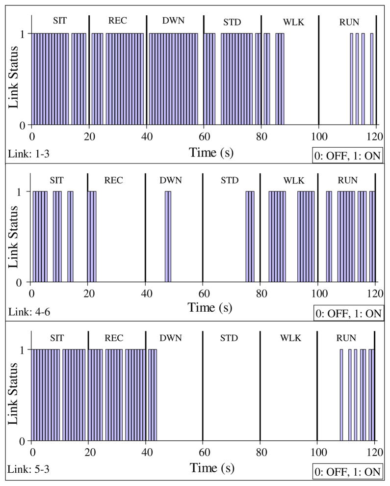
Experiments were carried out for observing the impacts of postural mobility on network partitioning. A human subject, fitted with seven sensors, was asked to follow a pre-determined sequence of postures (SIT, SIT-RECLINING, LYING-DOWN, STAND, WALK and RUN), each lasting for 20 s. The status of three WBAN links (1–3, 4–6, and 5–3) during such an experiment is shown in Fig. 2. The presence and absence of a link’s connectivity, as sampled by the nodes on the link, is represented by 1 and 0 respectively.
Fig. 2.
Variation of instantaneous link connectivity with postural mobility.
Each node maintains a neighbor table based on Hello messages sent periodically with low transmission power once in 1.4 s. A time-out period of 2.8 s. is used for purging entries from the neighbor table. The link status in Fig. 2 is constructed by combining the neighbor table information from the nodes relevant for the exhibited links. Experimentally, the neighbor table information is periodically sent by all seven on-body nodes to the out-of-body server (in Fig. 1) using the full transmission power of the Chipcon’s CC1000 radio.
The following observations can be made from Fig. 2. First, few links are connected only during certain postures, which can lead to significant topology variations and network partitioning across the postures. For instance, link 5–3 (between left front thigh and upper left arm nodes) shows the effect of distance on connectivity. The link is connected during most closed postures such as SIT and REC. However, for the stretched out postures such as LYING-DOWN, STAND and WALK, the link is mostly disconnected. Similar trends are observed for the other links including link 1–3 and link 4–6, as shown in Fig. 2.
The second observation is that even within a posture, a link may have intermittent disconnections (e.g. link 1–3 is disconnected during the SIT posture from ‘0–20 s’ interval). The reasons for such intra-posture disconnections include minor body movements, RF signal blockage by body segments and clothing material, and also the relative orientations of the node-pairs forming the link in question.
The topology level impacts of the body posture variation are reported in Fig. 3. Observe the wide swing of the node degree (1.5–3.8 across the six postures/activities) which indicates a high level of dynamism in the on-body mesh topology. Also observe the number of simultaneous network partitions which vary from 1 to 5, indicating frequent topological partitioning as hypothesized in Section 1.3. As expected, the postures with relatively lower node degree correspond to higher number of network partitions. Such topological disconnections necessitate on-body store-and-forward routing.
Fig. 3.
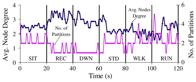
Instantaneous topology and partition properties with posture changes.
4. Store-and-forward routing with multi-scale movement locality
This section develops routing protocols that leverage short and long term node-interaction localities in the presence of partitioned and time-varying WBAN topologies as demonstrated in Section 3.
4.1. Postural link cost with multi-scale locality
As discusses in Section 2, a key requirement for store-and-forward routing in partitioned topologies is to be able to identify any spatio-temporal locality present in the node movement patterns. In the context of on-body topologies, we propose a novel paradigm of Postural Link Cost Formulation (PLCF) in which a time-varying cost is formulated for each WBAN wireless link based on the locality in the connectivity pattern for the link in multiple time scales. This postural link cost is then applied for executing store and forwarding protocols, which are an adaptation of Epidemic Routing [10] that leverages the localities of link connectivity in Delay Tolerant Networks (DTN). With posture and activity changes of a subject, the PLCF link costs are automatically adjusted such that the packets are forwarded to next-hops which are most likely to provide an end-to-end path with minimum intermediate buffering/storage delays. The link metric we propose is specifically designed to minimize data delivery delay by reducing the amount of packet buffering time at intermediate nodes.
Let us define a Link Likelihood Factor (LLF) which represents the likelihood for the link Li,j (between nodes i and j) to be connected during a discrete time slot t. If the quantity can be designed appropriately to track the locality of link connectivity then it can be used as the link cost [35] for probabilistic routing.
We propose that the LLF be dynamically updated after the tth time slot as:
| (1) |
When the link is connected, increases at a rate determined by the constant ω(0 ≤ ω ≤ 1), and the difference between the current value of and its maximum value, which is 1. As a result, if the link remains connected for a long time, the quantity asymptotically reaches its maximum value of 1. When the link is disconnected, asymptotically reaches zero with a rate determined by the constant ω. To summarize, for a given ω, the LLF responds to the instantaneous connectivity condition of the link Li,j.
Note that the LLF above captures the locality in short-term link connectivity in a manner conceptually similar to the age-based utility formulation, as developed in [26,33]. It is, however, not the same because in the designs in [26,33], the routing utility of a link is increased incrementally when the link is formed, and is reduced to zero as soon as the link is disconnected. This formulation of utility misses out the fact that even after disconnection, the formation probability of that link may be higher than a currently-connected link. In other words, those definitions of utility fairly differentiate across currently-connected links, but not across the currently non-connected links. In the formulation of utility in Eq. (1), motivated by the logic used in PROPHET [24], we track the short-term locality even when a link is not physically connected. This extended persistency in LLF is expected to improve performance over the existing age-based utility definitions as used in [26,33].
The next design step is to dimension the parameter ω for capturing link localities at a longer time scale. From Eq. (1), the rate of change of the LLF per time slot can be written as:
| (2) |
Eq. (2) indicates that for a high ω (e.g. 0.9), increases fast when the link is connected, and decreases slowly when the link is not connected. Conversely, for a low ω (e.g. 0.1), increases slowly when the link is connected, and decreases fast when the link is not connected. Ideally, it is desirable that for a historically good link (i.e. connected frequently on a longer time-scale), should increase fast and decrease slowly, and for a historically bad link, it should increase slowly and decrease fast. This implies that the parameter ω needs to capture the long-term history of the link; hence it should be link specific and time varying. Based on this observation, we define Historical Connectivity Quality (HCQ) of an on-body link Li,j at time slot t as:
| (3) |
The quantity is 1, if the link is connected (see Fig. 2) during the time slot r, and 0, if it is not connected. The constant Twindow represents a measurement window (in number of slots) over which the connectivity quality is averaged. The parameter indicates the historical link quality Li,j as a fraction of time the link was connected during the last Twindow duration. The parameter Twindow should be chosen based on the human postural mobility time constants. Experimentally, we found the optimal Twindow values that work well for a large number of subject individuals and range of postures to be in between 7 s and 14 s.
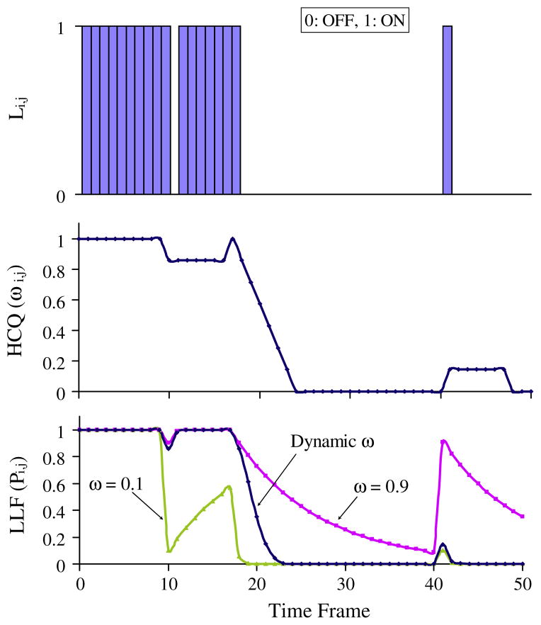
Fig. 4 shows the evolution of LLF ( ) and HCQ ( ) with time. The top graph shows an example link activity with the first half indicating a steadily connected link with a single frame (1.4 s) of disconnection at time frame 10, and the second half indicates a steadily disconnected link with single frame of connection at time frame 41 s. The middle graph shows the evolution of with a Twindow set to 7 frames. The bottom graph shows the evolution of with constant ω (i.e. 0.9 and 0.1) and link-specific time varying from Eq. (3), indicating the historical link quality. When the link is steadily well connected (during the first half), a high constant ω (i.e. 0.9) responds well to a momentary disconnection by decreasing slowly, but recovering quickly when the link becomes reconnected. A low constant ω (i.e. 0.1) responds poorly in this situation by doing just the opposite – that is a fast decrease and slow recovery.
Fig. 4.
Evolution of multi-scale locality in terms of LLF and HCQ.
Similarly, when the link is steadily disconnected (during the second half), a low constant ω (i.e. 0.1) responds relatively better than a high constant ω (i.e. 0.9) by increasing slowly for a momentary connection, and decreasing quickly after the link becomes disconnected. The lines for two constant ω values clearly show that a single constant value for ω is not able to handle both good-link and bad-link situations equally effectively.
As hypothesized, the link-specific and time-varying , on the other hand, is able to handle both situations well by mimicking the behavior of ω = 0.9 during the historically good-link situation, and that of ω = 0.1 during the historically bad-link situation. These results clearly demonstrate the effectiveness of the HCQ and LLF concepts for designing routing utilities that can capture both short and long-term localities of the on-body link dynamics. With this multi-scale approach, the proposed mechanism should be able to outperform both age-based (utility) [26,33] and probabilistic [24] routing protocols that use only short-term locality information.
Note that unlike the entities in Figs. 2 and 3, the LLF and HCQ in Fig. 4 show the link connectivity localities which depends on the short and long-term history of the link. The localities captures in Eqs. (1) and (3) are responsible for this memory based behavior in Fig. 4 in contrast with the instantaneous behavior in Figs. 2 and 3.
4.2. Probabilistic routing with postural link costs (PRPLC)
Combining Eqs. (1) and (3), an on-body node-i can construct and maintain the Link Likelihood Factor , for all j ∈ N, j ≠ i, where N represents all WBAN nodes (i.e. seven nodes in Fig. 1). In other words, a node observes and maintains its likelihood to be in direct (one-hop) contact with all other nodes in the network at any given point in time. The routing goal is to reduce the end-to-end packet delivery delay by choosing high likelihood links, thus reducing the intermediate storage delay caused due to packets stuck at nodes on low likelihood links.
The routing philosophy is when a node-i needs to forward a packet to node-d (d is the sink node), and it meets a node j, the packet is forwarded from node-i to node j only if the condition is found true. In other words, a higher link likelihood of node j to node-d indicates that the latter is more likely to meet node-d than what node-i’s chances are. That justifies the packet transfer from node-i to node-j with a goal of minimizing the end-to end packet routing delay.
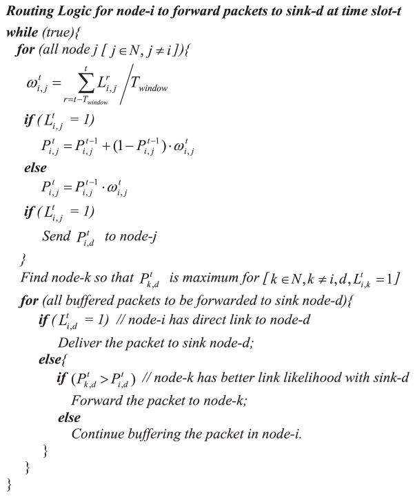
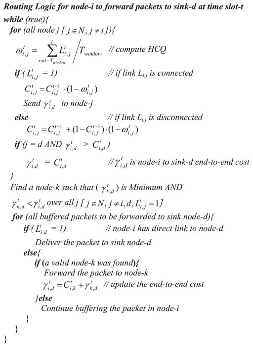
This forwarding logic assumes that each on-body node is guaranteed to intermittently come within up to 2-hop distance from the destination node. In other words, node-i is intermittently able to see other nodes that intermittently come in direct contact with node d. In our experimental topology this assumption was always found true. In fact for a WBAN topology, it is generally true that depending on the specific postural patterns, all nodes intermittently form direct links with all other nodes in the network. This observation makes the assumption generally applicable for WBANs which usually have a small network diameter. This distributed routing mechanism for a multipoint-to-point implementation is summarized in the pseudo-code presented in Fig. 5. An extension of link cost formulation without the above assumption is presented in Section 7.
Fig. 5.
PRPLC routing with LLF capturing multi-scale connection localities.
Each on-body sensor node needs to execute the algorithm as presented here. Using the periodic Hello mechanism, as outlined in Section 3.2, each node-i gradually develops the values with all other nodes in the network. The node also uses the same Hello messages to send the quantity , its Link Likelihood Factor (LLF) with the common destination node-d (e.g. node-6 in Fig. 1), to all other nodes that are currently connected to node-i. This way, each node will know the individual LLFs of all of its direct neighbor nodes to the common destination node-d.
At any given point in time, if there are packets stored in node-i’s buffer (originated at node-i or at some other node), node-i checks if any of its directly connected neighbors has a higher LLF to the destination node-d compared to its own LLF to node-d. If node-i’s LLF is the highest then it continues to keep the packet in its own buffer. Otherwise it finds the directly connected node with the highest LLF to the destination node-d, and forwards packets to that node. This ensures that node-i forwards a packet to the node that is most likely to meet the destination node, thereby reducing the expected end-to-end delivery delay.
While the pseudo-code in Fig. 5 shows a multipoint-to-point implementation for traffic from all on-body nodes to a common destination, the same concept is applicable for point-to-point routing. In that case, each node will require maintaining the Link Likelihood Factors (LLFs) to all possible destinations as opposed to only the common destination, as done in Fig. 5. Another difference will be that each packet may be forwarded to different next hops depending on its specific destination. The rest of the forwarding logic will be similar to what is presented in Fig. 5.
4.3. Single-copy probabilistic routing (PROPHET)
A single-copy version of the probabilistic routing protocol PROPHET [24], which uses only short-term link locality information, is implemented in our laboratory prototype for comparing it with the proposed PRPLC with multi-scale link localities. PROPHET relies on epidemic algorithms by doing pair-wise exchange of packets between nodes (as they come in contact with each other) to eventually deliver them to destinations. At a node A, a probabilistic metric called delivery predictability, is established for each of its known destinations B. This metric indicates how likely it is for node A to be able to deliver a message to destination B.
Nodes buffer packets if there is currently no available path to the destination. An index of these packets called a summary vector is maintained by the nodes, and when two nodes meet they exchange summary vectors. Updated summary vector information is then used to decide which packets to request from the other node. In the evaluations in [24], the forwarding strategy is when two nodes meet, a packet is transferred to the other node if the delivery predictability of the destination is higher at the other node.
The concept of delivery predictability in PROPHET has some similarities with the Link Likelihood Factor used in the PRPLC routing, and is updated [24] via three update equations using update constants Pinit, γ, and β. Since these update constants are not designed to be link-specific and they do not adapt with historical link qualities, the protocol PROPHET somewhat corresponds to the constant ω scenarios in PRPLC as explained in Fig. 4 and Section 4.1. As a result, while the Link Likelihood Factor with adaptive historical link quality in PRPLC can capture the long-term localities in postural body movements, it is not possible via the delivery predictability updates using constant Pinit, γ, and β, as used in PROPHET. The performance benefits of PRPLC over the generic design of PROPHET will be presented in Section 5.
4.4. Distance vector routing with postural link costs (DVRPLC)
In DVRPLC, nodes maintain end-to-end cumulative path cost estimates to the common sink node. As in PRPLC, the primary goal is to reduce the end-to-end packet delivery delay by choosing a high likelihood end-to-end path, thus reducing the intermediate storage delay caused due to packets buffered at nodes on low likelihood links.
Let us define a Link Cost Factor (LCF) which represents the routing cost for the link Li,j (between nodes i and j) during the discrete time slot t. We propose that the LCF be dynamically updated after the tth time slot as:
| (4) |
When the link is connected, decreases at a rate determined by( ), where is the Historical Connectivity Quality, as defined in Eq. (3). If the link remains connected for a long time, the quantity asymptotically reaches its minimum value 0. When the link remains disconnected, increases at a rate determined by the quantity ( ), and the difference between the current cost and its maximum value 1. This formulation ensures that a link’s routing cost always reflects the likelihood of the existence of the link while capturing its historical connectivity trends. Note that the time evolution of LCF in DVRPLC follows a rationale that is very similar to that of LLF in PRPLC. The main difference is that while the LCF reduces for connected links, the LLF increases in such situations. Similar difference exists when a link remains disconnected. To summarize, like in PRPLC the cost in DVRPC captures both short and long term link localities for minimum delay packet routing.
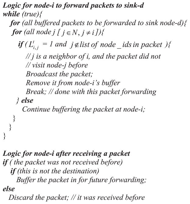
Let be the end-to-end cumulative cost from node-i to the sink node-d. According to distance vector routing logic, when a node-i needs to forward a packet to the sink node d, and it meets a node j, the packet is forwarded to node j only if the condition is found true. In other words, a lower path cost through node j indicates that the latter is more likely to forward the packet to node d than what node-i’s chances are. That justifies the packet transfer from node-i to j with a goal of minimizing the end-to-end packet routing delay. This distributed routing mechanism for a multipoint-to-point implementation is summarized in the pseudo-code presented in Fig. 6.
Fig. 6.
DVRPLC routing with link cost capturing multi-scale connection localities.
Note that the DVRPLC protocol attempts to minimize end-to-end cumulative routing costs. The objective is that due to this end-to-end cost minimization, DVRPLC should be able to outperform (from a delay standpoint) PRPLC which always interprets its LLF only at the link level and not in an end-to-end cumulative manner.
To execute the algorithm in Fig. 6, each on-body sensor node-i uses the periodic Hello mechanism, as outlined in Section 3.2, in order to gradually develop the values with all other nodes in the network. It also iteratively updates the quantity using the computed values with respect to all its neighbors. The node then uses the Hello mechanism to send the quantity , its end-to-end cumulative path cost to the common destination node-d (e.g. node-6 in Fig. 1), to all other nodes that are currently connected to node-i. This way, each node gets updated about the path costs of all of its direct neighbors’ to the common destination node-d.
4.5. On-body Store and Flood Routing (OBSFR)
In order to determine the best case delay performance among the above protocols, On-body Store and Flood Routing (OBSFR), a modified flooding protocol for partitioned networks, has been implemented. With flooding, multiple copies of a packet from a source node can reach to the destination through multiple routes, and the first arrived copy at the destination indicates the minimum possible end-to end storage/buffering delay that can be achieved by PRPLC and DVRPLC protocols.
Although a regular packet flooding mechanism can be applied to this application, a few additional routing syntaxes are needed in order to avoid packet losses in certain scenarios that arise specifically due to network partitioning. In addition to a unique identifier {source_id., seq_No.}, a packet also carries a list of node-ids indicating its path so far from the source node. When a node-i receives a packet for the first time (detected from its unique identifier), it buffers the packet till it encounters at least one node that is not there in the list of node-ids found in the packet. Upon encountering at least one such node, the packet is handed over from i to such nodes using broadcast, and then deleted from i’s buffer. Like in regular flooding, upon any subsequent reception of the same packet, node-i will ignore it.
This modified flooding protocol is used for reducing the number of packet drops in the presence of network partitioning. Consider the following situation. Using the conventional flooding (i.e. not using the list of node-ids) when node-i broadcast the packet to a node j, it is possible that node j had already broadcast forwarded the same packet and therefore it simply discards it after receiving from node-i. If node-i and node-j are currently forming a network partition that does not contain the packet’s destination, then the packet is dropped from this partition and will never be forwarded to its final destination.
However, with the modified flooding that uses the list of node-ids, node-i will not broadcast the packet to node j, since in this situation node j is already in the list of node-ids in the packet. As a result, node-i will buffer the packet till it encounters a node that is not already traversed trough by the packet in question. This improves the chance for the packet to be forwarded out of the current partition (formed by nodes i and j), thereby reducing the overall packet loss probability. This modification can be applied only to small networks with few nodes, and will not scale for large sensor network with tens of nodes to be added in the list of node-ids in the packets.
Note however that even with the above flooding modifications there exists a partition packet saturation situation in which a packet may be lost. Consider the scenario in which after node-i receives a packet for the first time it gets into a partition with two other nodes p and q so that all three nodes are fully connected within the partition. Now since nodes p and q do not appear in the list of node-ids in the packet, node-i will broadcast forward the packet to both nodes p and q and delete it from its own buffer. At this point, nodes p and q will broadcast forward the packet to each other since q does not appear in the list of p’s copy and p does not appear in the list of q’s copy of the packet. After this round of forwarding, both p and q will also delete the packet from their own buffers. This will cause the packet to be dropped from this partition and will never be forwarded to its final destination. The OBSFR mechanism for a multi-point-to-point implementation is summarized in the pseudo-code presented in Fig. 7.
Fig. 7.
OBSFR routing logic for packet delay lower-bound.
In spite of these occasional packet drops, this On-body Store and Flood Routing (OBSFR) protocol ensures that the successfully flooded packets to the destination do represent the minimum possible packet delivery delay that can be achieved by our proposed PRPLC protocol. However, due to its inherent flooding nature, the transmission energy cost for OBSFR will be expected to be significantly larger compared to PRPLC, DVRPLC, PROPHET, and other utility based mechanisms.
Note that in the absence of network congestions in low data-rate WBANs, the storage delays due to topological disconnections are usually much larger compared to the congestion delay. The protocol OBSFR is designed to deliver the delay lower-bound in the absence of any delays caused due to packet congestions.
Although the broadcast based Epidemic Routing (ER) [32] could have been used for finding the delay lower-bounds, we have chosen to implement OBSFR for the following reasons. First, unlike in ER which requires summary vector exchange across neighbor nodes to minimize content transfers, OBSFR uses a node-list in each packet to accomplish the same goal. This helps OBSFR to significantly reduce wireless traffic and energy drainage compared to ER, especially when large numbers of packets are buffered. Second, while in ER a node continues to buffer content even after it is given to another node epidemically, in OBSFR, the provider node removes the packet from its buffer, leading to a much smaller buffer budget compared to ER. The flipside of the above two aspects is that in certain rare situations as explained above as partition packet saturation, OBSFR may not be able to deliver a packet to its desired destination. But its significant capacity, buffer, and energy advantages over the Epidemic Routing, especially in the context of the resource-constrained WBAN sensors, have prompted us to design OBSFR which uses mores constrained flooding than ER, and can work efficiently in a small WBAN with only few nodes.
5. Experimental performance
The same seven sensor laboratory prototype network, as shown in Fig. 1, is used for the results presented in this section. Packets originated from all on-body sensors were routed to the common destination node-6, attached on the right ankle. Most presented results correspond to packets originated from node-3, representing the longest hop (i.e. also worst case) packet routing scenario in most of the body postures. Few results have also been presented for packets originated from node-5 and node-1, indicating the generality of our proposed routing from other segments of the body as well.
5.1. Polling based channel access for collision control
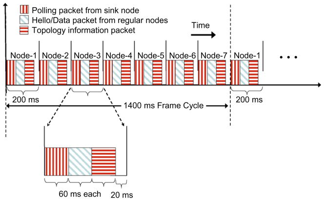
In order to avoid the CSMA MAC collisions inherent to Mic2Dot’s TinyOS networking stack, we have implemented a higher layer polling based TDMA access strategy that is managed by the common sink node (i.e. node-6 in Fig. 1). The primary motivation for TDMA over CSMA access strategy is to operate the WBAN in an energy-efficient manner. The sink node polls the other on-body sensors in a round-robin fashion. A node forwards its packets (both data and Hello) only when it is polled by the sink for giving access to the channel. For our seven-node network (see Fig. 1), a polling time frame of 1.4 s is used which is divided into seven time slots, one for each on-body node (the sink node also needs a slot for sending Hello packets etc. for link cost formulation as described in Section 3). Although the data packets and the Hello messages from the nodes are transmitted at power adjusted transmission range of 0.3–0.6 m for emulating the low transmission range as outlined in Section 3.1, the polling control packets are transmitted by Node-6 at full power so that all on-body nodes receive such packets for effective polling, leading to collision-free channel access. If a node misses a polling packet from node-6, it simply misses one transmission opportunity.
As shown in Fig. 8, each 1.4 s frame is divided into seven 200 ms time slots. . Each slot is further divided into three 60 ms sub-slots and a 20 ms guard time between adjacent slots. The first sub-slot is used for channel access polling packets from the sink node at full power. The second sub-slot is used for data and Hello packet exchange between on-body nodes at low power, emulating the transceivers discussed in Section 3.1.
Fig. 8.
Collision-free MAC access via polling.
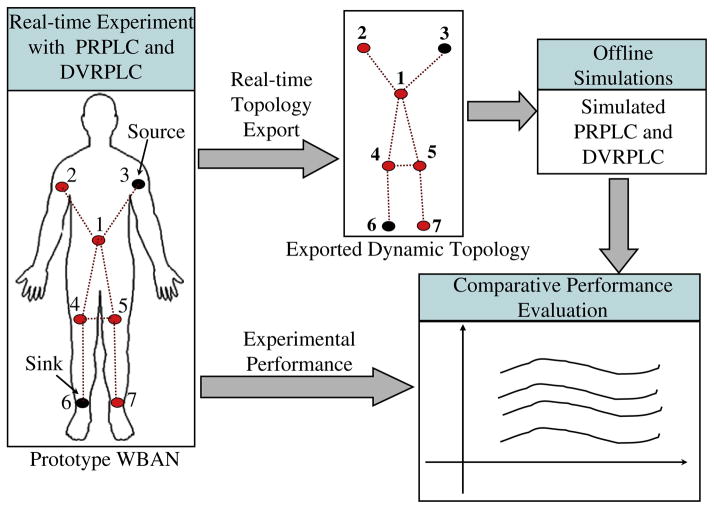
The third sub-slot is used for a topology gathering process in which each on-body node sends its neighbor information to an out-of-body machine (see Fig. 1) at full transmission power. Using time-stamped neighbor information from each on-body node, it is possible to reconstruct the on-body topology evolution as a result of postural body movements. As presented in Section 6, such reconstructed topology information is used for off-line simulation analysis of the proposed packet routing algorithms.
5.2. Performance metrics
The performance of on-body routing is evaluated using three commonly used [25,27,30,33] primary metrics, namely, end-to-end Packet Delay (PD), Packet Hop Count (PHC), and Packet Delivery Ratio (PDR). The index PHC is a direct measure of the communication energy (i.e. for transmission and reception) expenditure of the routing mechanism. Unlike for routing in conventional un-partitioned networks, the PD in partitioned on-body networks depends mainly on the storage delay at the intermediate nodes as a result of network disconnection. The PHC here mainly impacts the number of transmissions per packet forwarding, indicating the energy expenditure; it does not impact the packet delay so much. The target is to minimize PHC while also minimizing the PD by avoiding large packet storage delays by routing a packet through links with low disconnection probabilities or high Link Likelihood Factor as defined in Section 4.1. The PRPLC protocol, as presented in Section 4.2, is designed mainly to minimize the on-body PD values.
5.3. Traffic generation and data collection
The source node generates a data packet every four polling frames (each frame is 1.4 s), with a packet size of 46 bytes. Each packet is marked with a monotonically increasing packet-ID so that by observing the received packet-ID, the Packet Delivery Ratio (PDR) can be computed. Also, all on-body network nodes are coarse-grain time-synchronized by the sink node-6 at the beginning of each polling frame. This allows single-trip Packet Delay (PD) to be computed from a source node to the sink node-6. On its way to the sink node, a data packet collects the entire route information in the form of a list of the intermediate node-ids. This allows the extraction and analysis of route information including the PHC values.
5.4. Packet Delay (PD)
End-to-end packet delivery delays from source node-3 on the left upper arm to the sink node-6 on right ankle for PRPLC and DVRPLC are reported in Fig. 9. Three different versions of PRPLC and DVRPLC was implemented; two with static values of ω (i.e. 0.9 and 0.1) and one with adaptive ω, capturing the long-term locality in terms of Historical Connectivity Quality of the on-body links. For each of these scenarios, a separate experiment was run for 1320 s. (i.e. 22 min), sending 230 packets, and spanning 6 different postures (SIT, SIT-RECLINING, LYING-DOWN, STAND, WALK and RUN), each lasting for 20 s. Fig. 9 reports the average of packet delay computed from each such experiment. All adaptive ω results correspond to a connectivity quality measurement window (i.e. Twindow) of seven polling frames or approximately 9.8 s. Value of Twindow in this neighborhood has shown to demonstrate the best performance for multiple subject individuals, indicating a fairly good estimation of the time constant of the long-term postural movement locality.
Fig. 9.
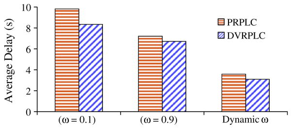
Packet delivery delays with static and adaptive ω scenarios.
The following observations can be made from Fig. 9. First, with adaptive ω, both PRPLC and DVRPLC protocols are able to successfully capture the long-term locality in postural movements (see Section 4.1). As a result, the packet delays for the adaptive ω scenarios (3.6 s and 3.11 s for PRPLC and DVRPLC respectively) are significantly reduced compared to those for the constant ω implementations which leverage only the short term movement locality as explained in Section 4.1. Second, with all implementations, DVRPLC achieves better packet delay compared with PRPLC, mainly because of its end-to-end path cost formulation as explained in Section 4.4. Because of its delay superiority, this point onwards we will present results only for the adaptive ω scenarios. Unless stated otherwise, the references to the protocols PRPLC and DVRPLC will correspond to their adaptive ω implementations, reflecting the multi-scale locality which was not captured in PROPHET [24] and other utility based mechanisms [26,33] in the literature.
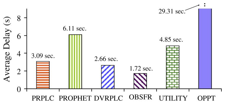
Fig. 10 reports the experimentally obtained average packet delays for a number of protocols including the proposed PRPLC, DVRPLC, OBSFR, an utility-age based protocol (UTILITY) [33], an opportunistic protocol (OPPT) [27], and the single-copy probabilistic protocol (PROPHET) (with its delivery predictability update constants Pinit, γ, and β chosen as 0.75, 0.98, and 0.25 as reported in [24]). Observe that the flooding protocol OBSFR achieves significantly better packet delay (i.e. the experimental lower bound) compared to the other protocols mainly due to its multi-forwarding nature as explained in Section 4.5. On the other extreme, the opportunistic protocol (OPPT), in which a source node delivers a packet to the destination only when it experiences a direct link with the destination, shows the worst delay because of the very low connection frequency between the source node-3 and the destination node-6 in Fig. 1. With static update constants Pinit, γ, and β, PROPHET suffers from the same shortcomings (i.e. leveraging only the short-term locality) of PRPLC with constant ω, as shown in Fig. 9. As explained in Section 4.1, the age-based utility approach (UTILITY) also suffers from the same short-term-only locality, which explains its poor performance compared to the packet delays for PRPLC and DVRPLC (i.e. 3.6 s and 3.11 s). With adaptive ω, these two protocols are able to successfully capture the multi-scale link localities caused due to postural body movements. It should be noted that in spite of their superior delay performance with respect to PROPHET and age-based UTILITY, there is still room for improvement when compared to the experimental delay lower-bound as demonstrated by the OBSFR flooding protocol.
Fig. 10.
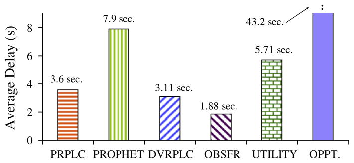
On-body packet delivery delay for different DTN routing protocols.
5.5. Packet Hop Count (PHC)
PHC serves as a measure for routing energy expenditure (i.e. for transmission and reception) for the on-body sensors. Fig. 11 demonstrates the distribution of PHC experimentally obtained for all the protocols implemented on our prototype.
Fig. 11.
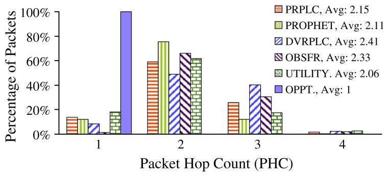
Distribution of Packet Hop Count (PHC).
The figure shows that packets in DVRPLC and OBSFR take slightly longer routes compared to the other protocols. As shown in Fig. 10, the packets in those two protocols also experience the lowest packet delay. This means that the DVRPLC and flooding protocols route packets through better quality links, leading to smaller delays, even though it requires more number of end-to-end hops. The distribution graph in Fig. 11 also shows that while majority of the packets from node-3 to node-6 are routed in 2-hops, certain packets take one, three, or four hops. Also note that certain packets are delivered directly from node-3 to node-6 (from the upper left arm to the right ankle in Fig. 1), especially during the closed postures such as sitting. Since in the opportunistic routing protocol (OPPT) packets are delivered only when a source node comes in direct contact of the destination, all packets are delivered with PHC 1.
Fig. 12 shows the number of data packet transmissions. It is computed as the ratio of the total number of transmissions and the number of successfully delivered packets at the sink. This index captures the additional forwarding costs for multiple packet transmissions in flooding based protocols such as OBSFR. The large number for OBSFR explains the impacts of its multi-forwarding compared to all other single-copy DTN routing protocols. Note that there were no link layer packet retransmissions during these experiments; any channel errors have resulted in dropped packets, and are captured by the Packet Delivery Ratio (PDR) reported in the following section.
Fig. 12.
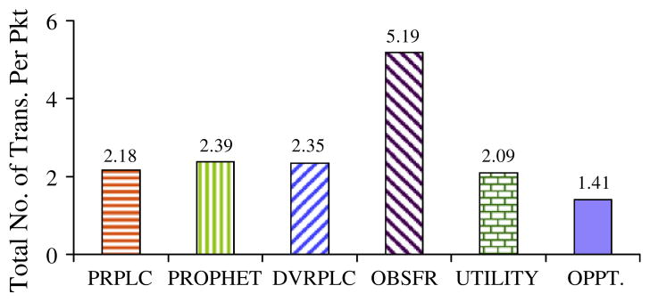
Number of transmissions per delivered packet.
5.6. Packet delivery ratio
Packet losses are observed due to the following two reasons. First, due to postural mobility, there are transient blackout periods during which a neighbor may appear to be connected in a node’s neighbor table, when in fact it is no longer connected. These blackout periods are created during a node’s neighbor time-out period, which is in the vicinity of 2.8 s, as reported in Section 3.2. Packet transmissions during such blackout periods end up in packet losses since no link layer reliability is used. All six protocols suffer from such packet losses. The second type of losses, applicable only to flooding, is due to the partition packet saturation, as explained for the OBSFR protocol in Section 4.5.
Fig. 13 demonstrates that due to its multi-packet forwarding, the flooding based OBSFR looses fewer packets compared to all the other protocols, even though the packet losses due to partition packet saturation are present only for OBSFR. Poor PDR for the OPPT protocol in this case was caused due to a very unreliable link between the source and the destination nodes (i.e. nodes-3 and −6 in Fig. 1) which are physically situated at two extremes of the subject’s body. Since the OPPT protocol relies on direct source–destination contact for packet delivery, the source–destination link quality affects this protocol most.
Fig. 13.
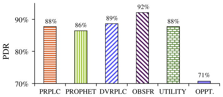
Packet delivery performance.
5.7. Routing packets from and to different body segments
Delivery delays for packets from different body segments to the sink node placed on the right ankle (i.e. node-6 in Fig. 1) are shown in Fig. 14. Observe that as the physical distance between a source and the destination increases, the average packet delays for all the protocols increase. Relatively though, all the experimented routing protocols maintain the same trend for the packet delay as observed in Section 5.4. The average packet hop-counts from source nodes-5, −1, and −3 were experimentally logged in the range of 1.25, 1.5, and 2.3 respectively.
Fig. 14.
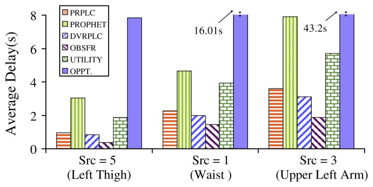
Delivery delay for packets from thigh, waist and arm to right ankle (i.e. node-6).
Delivery delays for packets from the upper left arm (i.e. node-3) to different body segments are shown in Fig. 15. It should be noted that although the absolute delay values are different, the overall trend in packet delay follows the same pattern for all the sink nodes that we have experimented with.
Fig. 15.
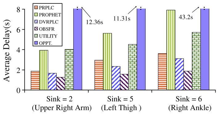
Delivery delay for packets to arm, thigh and ankle from the upper left arm (i.e. node-3 in Fig. 1).
5.8. Impacts of postural stability
For all the experiments so far, each individual physical posture was made to last for 20 s. In order to study the impacts of variable postural stability on the routing performance, the subject was instructed to repeat the same sequence of postures as in Section 3, but with different posture durations ranging from 10 s to 40 s.
Fig. 16 shows the impacts of posture duration on average packet delay for all six on-body routing protocols. Due to its significantly higher values, the packet delays for the OPPT protocol are plotted as a separate axis in Fig. 16. Observe that the packet delays for all the protocols generally increase with higher posture durations. This is because longer posture duration implies that a connected link remains connected for longer duration and also a disconnected link remains disconnected longer. As a result, a packet that is buffered in a node due to network partitioning remains buffered for longer duration, leading to higher end-to-end packet delay. In a relative sense, all the experimented protocols maintain the same performance trend for the packet delay as observed in Section 5.4, Fig. 10.
Fig. 16.
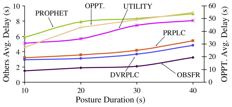
Impacts of posture duration on packet delay.
Fig. 17 shows the impacts of posture duration on the PDR metric. As explained in Section 5.6, the primary reason for drops is transient blackouts due to postural mobility. With higher posture durations, the degree of mobility is less, and therefore the drops are less frequent. This explains a general increase in packet delivery ratio with higher posture durations.
Fig. 17.
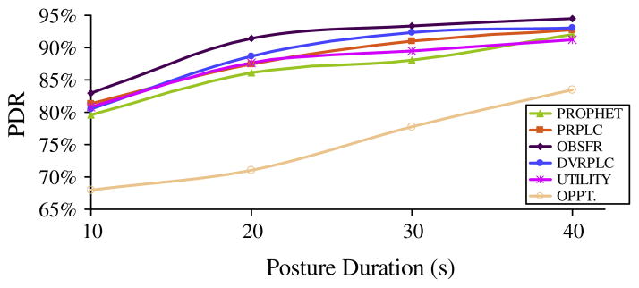
Impacts of posture duration on packet delivery ratio.
5.9. Impacts of Intra-posture movements
All the experiments so far correspond to the inter-posture sequence (SIT, SIT-RECLINING, LYING-DOWN, STAND, WALK and RUN), as introduced in Section 3.2. Fig. 18 presents packet delay for similar experiments, but carried out with an intra-posture sequence comprising of the positions SIT, SIT-RECLINING, RECLINING-RIGHT-CROSS, RECLINING-LEFT- CROSS, RECLINING-RAISED-RIGHT, and RECLINING-RAISED-LEFT, where CROSS and RAISED refer to cross-legged and leg-raised sub-postures while sitting. The primary objective of these intra-posture experiments is to study the impacts of higher granularity postural movements on the on-body routing protocol performance.
Fig. 18.
Packet delivery delay with intra-posture movement.
Comparing the performance in Fig 18 with those for inter-posture movements in Fig. 10, it can be observed that the relative performance trends across all the six protocols are still maintained for this high granularity intra-posture case. The absolute delay values, however, have been slightly reduced due to a better overall connectivity compared to the inter-posture case. Similar trends were consistently observed from many more inter- and intra-posture experiments carried out during this work.
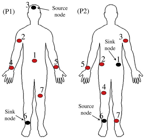
5.10. Impacts of sensor placements
Additional on-body sensor placements, as shown in Fig. 19, were experimented with for evaluating the validity of the routing results obtained so far from the sensor placement shown in Fig. 1. Different source and sink nodes are used in the two placement settings P1 and P2 in Fig. 19. The inter-posture sequence, described in Section 3.2, was followed by the subject and the corresponding packet delay results are presented in Fig. 20 for the placement settings P1 and P2 in Fig 19. Generally, the relative performance trends across all the experimented protocols as observed for the original sensor placement (in Fig. 10) remain valid for the new sensor placements P1 and P2 in Fig. 19. The delay for the placement P1 is larger due to the longer source-to-destination distance compared to that in P2.
Fig. 19.
Experiments with different sensor placements.
Fig. 20.

On-body packet delay for: (a) sensor placement P1 and (b) sensor placement P2.
6. Off-line simulation with experimentally obtained topology
The objective of this section is to develop an off-line simulation framework that uses network topology traces obtained during the on-line experiments described so far. The motivations for such simulation are to: (1) validate the correctness of the experimental results, (2) determine a benchmark performance with the minimum possible delay for a given posture/topology sequence, (3) develop a mechanism for offline experimentation with new protocols, before implementing them online which is significantly more experimentally involving.
In order to keep the results comparable, the simulation is performed on the exact same topology sequence used for the experiments. During the experiments described in Sections 3 and 4, all seven on-body nodes periodically export their neighbor table to an out-of-body machine using full transmission power. This external machine then derives the experimental topology sequence by combining the time-series neighbor table information. The off-line simulation is performed on this topology sequence and the results are then compared with those obtained experimentally. This arrangement is summarized in Fig. 21.
Fig. 21.
Experimental topology export for off-line simulation.
6.1. Delay benchmark
In order to determine the best case end-to-end delay performance, an offline route search algorithm, Backward Search for Delay Benchmark Routing (BSDBR) has been developed. As long as the entire topological sequences for a dynamically partitioned network are known a priori, the BSDBR algorithm is able to compute the most delay optimal end-to-end path for each packet depending on its source, destination, time of origin, and the complete topological sequence information. BSDBR is designed to be an offline centralized search algorithm, to be executed in the presence of entire time series topology information.
Let t0 be the time instant at which a packet is generated at node-i and routed towards destination node-d. Given a known topology sequence, the objective is to find the earliest time instant after t0 at which the packet can be delivered to the destination. Let t1 be the earliest time instant (t1 > t0) at which destination node-d comes in contact with any other node-j (j ∈ N, j ≠ d). The minimum possible delivery delay for the packet originated at time t0 can be written as (t1 − t0). This minimum delay is possible only if the necessary network links are formed across the network during the time interval [t0 to t1] so that the packet could be forwarded multi-hop all the way from the origin node-i to node-j before time t1. The objective of BSDBR search process is to scan the network topology sequence in order to find if such link formations are there so that (t1 − t0) can represent the minimum packet delivery delay.
If the search process concludes that the packet cannot be delivered by time t1, then the next feasible time instant t2 is identified and a similar search is conducted to determine if (t2 − t0) can be the minimum delivery delay. The quantity t2 is the earliest time instant after t1 (t2 > t1) at which destination node-d comes in contact with any other node-j (j ∈ N, j ≠ d). This BSDBR search process is iteratively continued till a valid minimum delivery delay (tr − t0) is found. The time instant tr corresponds to the earliest contact time so that the necessary network links are formed across the network during the time interval [t0 to tr] so that the packet can be forwarded multi-hop all the way from the origin node-i to destination node-j by the time tr.
Note that the expected value of the packet delay lower-bound could have been computed using the Linear Programming formulation as adopted in the full knowledge based approach in [30]. Instead, we have chosen to implement BSDBR since it allows us to determine the minimum packet delay for each individual packet as opposed to their average in a statistical sense. Also, the formulation in [30] is more complex than BSDBR since it incorporates the effects of message queuing which is not studied in our implementation.
6.2. Simulated performance results
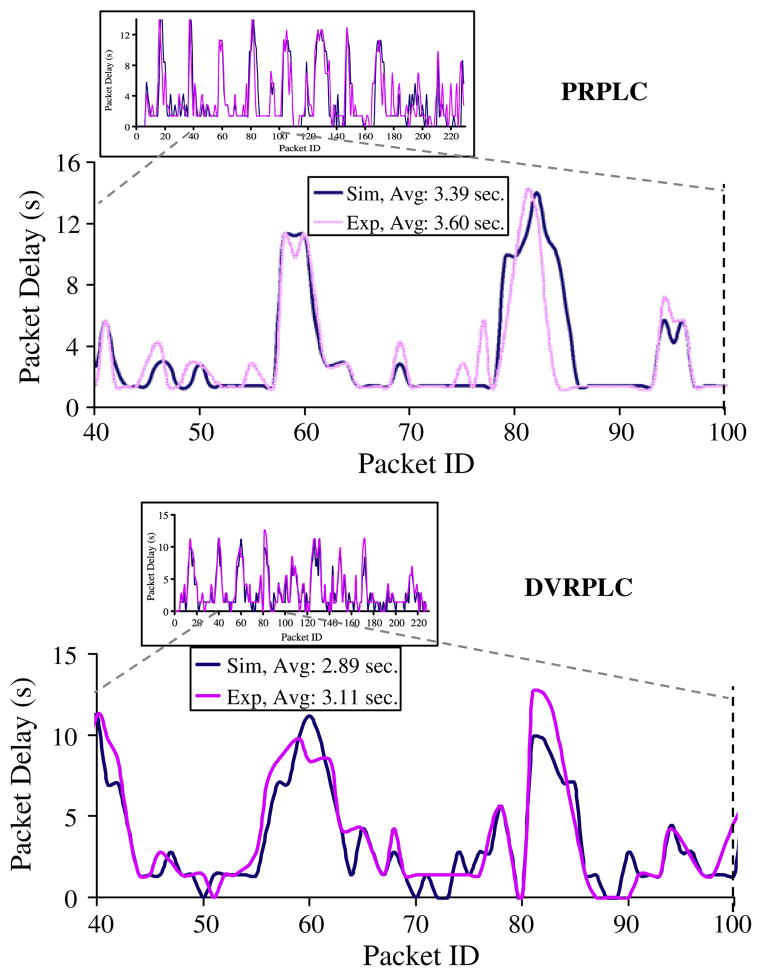
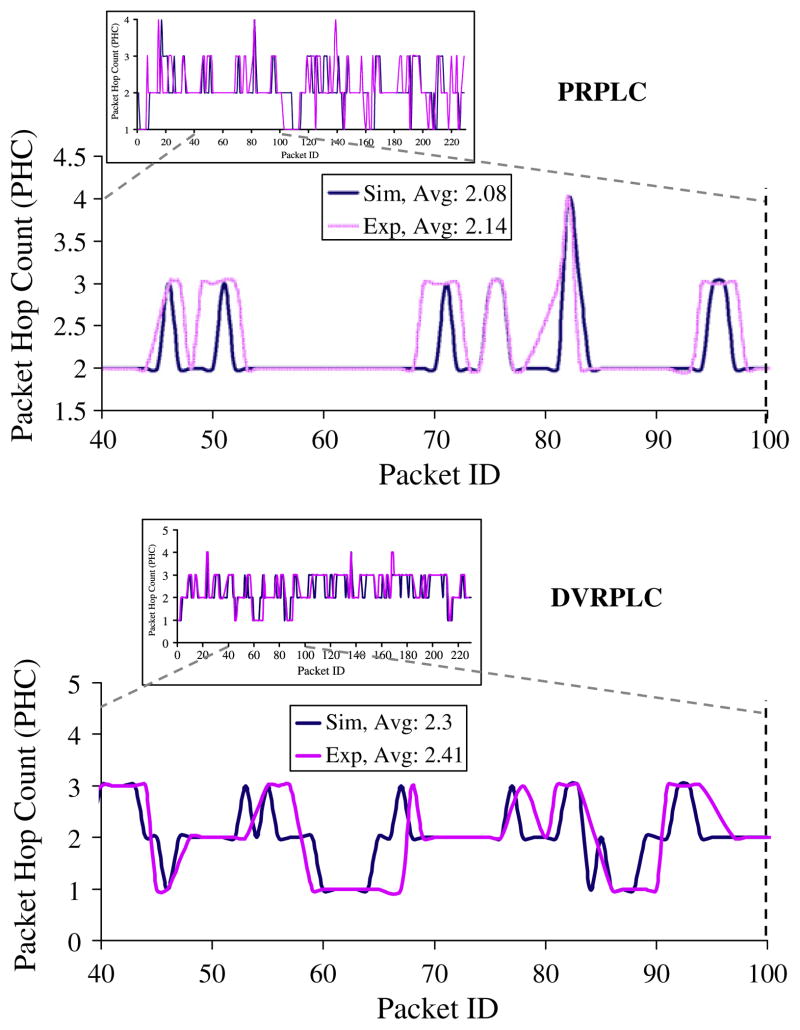
The same experimental topology sequence in Section 5 is used for the simulation results presented in this section. Packets are routed from node-3 to node-6 with a data rate of one packet every four frames. Fig. 22 shows the packet by packet delivery latency of PRPLC and DVRPLC from simulation and experiments for a total duration of 1320 s (or 22 min), involving transmissions of 230 packets for each protocol experiment. Fig. 23 reports the corresponding Packet Hop Count (PHC) from the same experiment.
Fig. 22.
Delivery delay from experiments and simulation.
Fig. 23.
Packet hop counts from experiment and simulation.
For clarity, delivery latency for the 40th to the 100th packets are zoomed in and shown in both Figs. 22 and 23. As expected, the simulated packet latencies are slightly better (approximately 7%) than the experimental values. However, the overall trends are very similar, indicating that the operations of the PRPLC and DVRPLC implementations within the prototype on-body network are very similar to the off-line simulation as arranged in Fig. 21. The primary reason for the performance loss in the experiments is the packet drops caused due to the reasons as explained in Section 5 and Figs. 13 and 17. For the off-line simulation, 100% packet delivery helps keeping the packet delivery latency slightly higher.
The PHC in Fig. 23 shows a very similar trend in which the simulation average is slightly better than the experimental results.
Fig. 24 reports the average packet delay of PRPLC and DVRPLC compared with BSDBR, UTILITY, OPPT, and PROPHET (with the constants Pinit, γ, and β chosen as in Section 5.4 and reported in [24]). For all the protocols, the same topology sequence which was extracted from the on-body experiments is used. Observe that PRPLC and DVRPLC achieve significantly better packet delay compared to that (5.79, 4.05 and 34.8 s) of PROPHET, UTILITY and OPPT respectively. This trend agrees with the experimental results reported in Section 5 and Fig. 10. Also note that the packet delay of PRPLC and DVRPLC are close to the best case offered by the benchmark obtained using BSDBR.
Fig. 24.
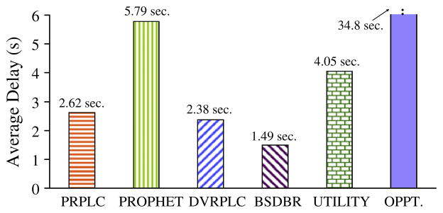
Simulated average packet delivery delay.
Fig. 25 shows the corresponding PHC performance. The figure shows that packets in BSDBR take longer routes compared to the other three protocols. As shown in Fig. 24, the packets in BSDBR enjoy the minimum packet delay. This means that BSDBR routes packets through better quality links, leading to smaller delays, even though it requires more number of hops. These results are very similar to the experimental results in Section 5.5 and Fig. 11, where the flooding based protocol OBSFR offers the best delay, but at the expense of longer routes. Fig. 25 also shows that the packets in DVRPLC are delivered using slightly longer routes compared with PRPLC, PROPHET, UTILITY and OPPT.
Fig. 25.
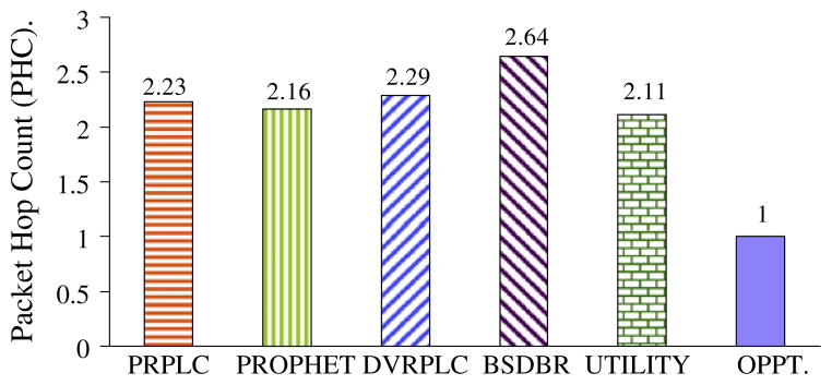
Simulated average of packet hop count.
7. PRPLC without 2-hop assumption
As explained in Section 4.2, the baseline PRPLC in Fig. 5 assumes that each on-body node intermittently comes within up to 2-hop contact of the destination/sink node. While this assumption is generally expected to be true for WBANs which usually have a small network diameter, in theory the assumption may get violated for networks with large diameters. In this section we generalize the link cost logic by using a transitive component [24].
7.1. Transitive update of Link Likelihood Factor
In the generalized case, a node-i may forward a packet to node j, event if node-j has never directly visited the sink/destination node-d. A consequence of this generalization is that the Link Likelihood Factor (LLF) of Li,j now can change not only based on the connectivity status of the link, but it can also increase based on the LLF of the intermediate nodes that node-i may meet over time. This transitive change of LLF can be captured by executing the following additional (to Eq. (1)) update equation when the link Li,k is connected.
| (5) |
The transitive update equation above indicates that if node-k has a high LLF to node-j, then every time node-i meets node-k, the LLF of link Li,j goes up by a factor that depends on the Historical Connectivity Quality (HCQ) of links Li,k and Lk,j. With the above addition of LLF update logic, the same logic in Fig. 5 can be used for packet forwarding. Note that in order to support the above transitive update, each node is required to report the LLF and HCQ information about all its neighbors in its periodic Hello messages.
7.2. Performance with transitive LLF update
Figs. 26 and 27 show delay and Packet Hop Count (PHC) performance of PRPLC from simulation experiments conducted with and without transitive LLF updates. For fair comparison, both sets of experiments were carried out on the same topology sequences. The same experimental settings as in Section 6 are used.
Fig. 26.
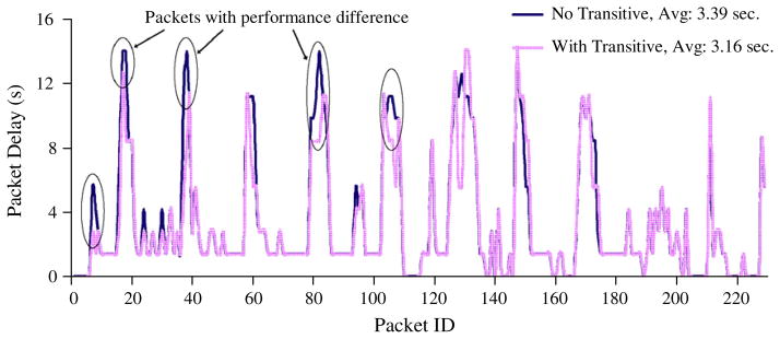
The impacts of transitive updates on delivery delay.
Fig. 27.
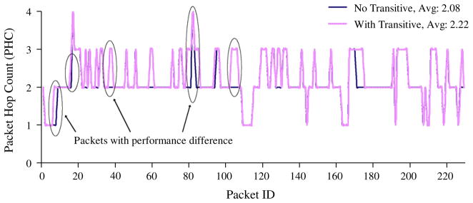
The impacts of transitive updates on Packet Hop Counts (PHC).
As shown in Fig. 26, the inclusion of transitive LLF update does slightly improve the packet delivery delay (approximately 6%). The packets for which there is an improvement are encircled in the figure. These improvements are caused mainly due to the fact that with transitive update, a node is now able to forward a packet to the sink through nodes that may never see the sink directly. This also means that for those packets that are delivered with lower delay will have higher hop counts. This explains the higher PHC number in Fig. 27 for PRPLC with transitive update. For example, in Fig. 26 packets 7, 8, 18, 38, 82 and 106 are delivered with lower latencies, but in Fig. 27, higher PHC is reported for delivering those packets.
Note that the delay improvements due to the transitive update mechanism remain limited due to the small WBAN diameter as explained in Section 4.2. For networks with larger diameter, more number of intermediate nodes will be available under the with-transitive version of the protocol, and the resulting delay improvements in those cases will be expected to be much higher.
8. Conclusion and ongoing work
Store-and-forward packet routing protocols for Wireless Body Area Networks (WBAN) have been developed in this paper. The concept of a stochastic link cost was introduced for enabling a probabilistic and a distance vector on-body routing protocol in the presence of postural mobility of human body. Performance of these proposed protocols were evaluated both experimentally and via simulation, and then compared with a generic probabilistic routing protocol and a specialized on-body packet flooding mechanism that provides the routing delay lower-bounds. It was shown that via successful modeling of the spatio-temporal locality of on-body link disconnection patterns, the proposed algorithms can provide better routing performance compared to the existing probabilistic routing protocols in the literature. Ongoing work on this topic includes developing a distance vector routing algorithm using a similar stochastic link cost metric, and developing a Kalman Filter based body movement prediction model for predictive on-body packet routing.
Biographies
 Muhannad Quwaider is a Ph.D. candidate in Networked Embedded and Wireless Systems (NEEWS) laboratory at the Electrical and Computer Engineering Department of Michigan State University (MSU), USA since 2005. Muhannad earned his M.S. at the Michigan State University, USA in 2005, and his B.S. at Jordan University of Science and Technology (JUST), Jordan, 2000. He has 5 years of research experience in wireless networking in NEEWS laboratory, and 3 year of teaching experience in MSU and JUST universities. His research interests include Body Area Networks, Mobile Ad hoc Networks, Wireless Topology Control and Application-specific Sensor Networks.
 Subir Biswas is an Associate Professor and the director of the Networked Embedded and Wireless Systems laboratory at the Michigan State University. Subir received his Ph.D. from University of Cambridge and he held various research positions in NEC Research Institute, Princeton, AT&T Laboratories, Cambridge, and Tellium Optical Systems, NJ. He has published over 90 peer-reviewed articles in the area of network protocols, and a co-inventor of four US patents. His current research interests include the broad area of wireless data networking, low-power network protocols, and application-specific sensor networks. He is a senior member of IEEE and a fellow of Cambridge Philosophical Society.
Footnotes
This work was partially supported by a grant (NNX09AK47G) from National Aeronautics and Space Administration (NASA).
References
- 1.Bao Shu-Di, Zhang Yuan-Ting, Shen Lian-Feng. Physiological signal based entity authentication for body area sensor networks and mobile healthcare systems. Proceedings of the 27th Annual International Conference of the Engineering in Medicine and Biology Society (IEEE–EMBS 2005); 2005. pp. 2455–2458. [DOI] [PubMed] [Google Scholar]
- 2.Lo B, Thiemjarus S, King R, Yang G. Body sensor network – a wireless sensor platform for pervasive healthcare monitoring. Proceedings of the 3rd International Conference on Pervasive Computing (PERVASIVE 2005); May 2005; pp. 77–80. [Google Scholar]
- 3.Otto C, Milenkovic A, Sanders C, Jovanov E. System architecture of a wireless body area sensor network for ubiquitous health monitoring. Journal of Mobile Multimedia. 2006;1:307–326. [Google Scholar]
- 4.Milenkovic A, Otto C, Jovanov E. Wireless sensor networks for personal health monitoring: issues and an implementation. Computer Communications. 2006;29:2521–2533. [Google Scholar]
- 5.Moh M, Culpepper B, Dung Lan, Moh Teng-Sheng, Hamada T, Su Ching-Fong. On data gathering protocols for in-body biomedical sensor networks. GLOBECOM ’05; Global Telecommunications Conference; 2005; IEEE; 2005. pp. 6–2996. [Google Scholar]
- 6.Jovanov E, Milenkovic A, Otto C, De Groen P, Johnson B, Warren S, Taibi G. A WBAN system for ambulatory monitoring of physical activity and health status: applications and challenges. Proceedings of the 27th Annual International Conference of the Engineering in Medicine and Biology Society (IEEE–EMBS 2005); 2005. pp. 3810–3813. [DOI] [PubMed] [Google Scholar]
- 7.Lee Seon-Woo, Mase K. Pervasive Computing. Vol. 1. IEEE; 2002. Activity and location recognition using wearable sensors; pp. 24–32. [Google Scholar]
- 8.Jovanov E, Milenkovic A, Otto C, Groen PCD. A wireless body area network of intelligent motion sensors for computer assisted physical rehabilitation. Journal NeuroEngineering and Rehabilation. 2005;2:6. doi: 10.1186/1743-0003-2-6. [DOI] [PMC free article] [PubMed] [Google Scholar]
- 9.Quwaider M, Biswas S. Body posture identification using hidden Markov model with a wearable sensor network. Proceedings of the ICST 3rd International Conference on Body Area Networks; Tempe, Arizona: ICST, Institute for Computer Sciences, Social-Informatics and Telecommunications Engineering; 2008. pp. 1–8. [Google Scholar]
- 10.WebPage of Department of Health and Human Services. < http://www.grants2.nih.gov/grants/guide/pa-files/PA-07-354.html>.
- 11.Chen K, Bassett DJ. The technology of accelerometry-based activity monitors: current and future. Medicine and Science Sports Exercise. 2005;37:490–500. doi: 10.1249/01.mss.0000185571.49104.82. [DOI] [PubMed] [Google Scholar]
- 12.Quwaider M, Biswas S. Physical context detection using multi-modal sensing using wearable wireless networks. Journal of Communication Software and Systems (JCOMSS’08) 2008;(4):191–202. (special issue on Medical Applications for WSN) [Google Scholar]
- 13.Lin S, Zhang J, Zhou G, Gu L, Stankovic J, He T. ATPC: adaptive transmission power control for wireless sensor networks. SenSys ‘06: Proceedings of the 4th International Conference on Embedded Networked Sensor Systems; ACM Press; 2006. p. 236.p. 223. [Google Scholar]
- 14.Xiao S, Sivaraman V, Burdett A. Adapting radio transmit power in wireless body area sensor networks. Proceedings of the ICST 3rd International Conference on Body Area Networks; Tempe, Arizona: ICST, Institute for Computer Sciences, Social-Informatics and Telecommunications Engineering; 2008. pp. 1–8. [Google Scholar]
- 15.Mikami S, Matsuno T, Miyama M, Yoshimoto M, Ono H. A wireless-interface SoC powered by energy harvesting for short-range data communication. Asian Solid-State Circuits Conference; 2005. pp. 241–244. [Google Scholar]
- 16.Sagan D. RF integrated circuits for medical applications: meeting the challenge of ultra low power communication. Ultra-Low-Power Communications Division. Zarlink Semiconductor. 2005 [Google Scholar]
- 17.Strömmer E, Hillukkala M, Ylisaukkooja A. Ultra-low power sensors with near field communication for mobile applications. International Conference on Wireless Network, ICWN”07; 2007. pp. 1–12. [Google Scholar]
- 18.Falck T, Baldus H, Espina J, Klabunde K. Plug ‘n Play simplicity for wireless medical body sensors. Pervasive Health Conference and Workshops; 2006. pp. 1–5. [Google Scholar]
- 19.Jones E, Ward P. Routing strategies for delay-tolerant networks. ACM Computer Communication (CCR); 2006. [Google Scholar]
- 20.Guo Hui, Li Jiang, Qian Yi, Tian Ye. A practical routing strategy in Delay Tolerant Networks using multiple pigeons. MILCOM 2008; Military Communications Conference; 2008; IEEE; 2008. pp. 1–7. [Google Scholar]
- 21.Leguay J, Friedman T, Conan V. Evaluating MobySpace-based routing strategies in delay-tolerant networks: research articles. Wireless Communications and Mobile Computing. 2007;7:1171–1182. [Google Scholar]
- 22.Conan V, Leguay J, Friedman T. Fixed point opportunistic routing in delay tolerant networks, selected areas in communications, Selected Areas in Communications. IEEE Journal. 2008;26:773–782. [Google Scholar]
- 23.Leguay J, Friedman T, Conan V. Evaluating mobility pattern space routing for DTNs. INFOCOM 2006. 25th IEEE International Conference on Computer Communications. Proceedings; 2006. pp. 1–10. [Google Scholar]
- 24.Lindgren A, Doria A, Schelén O. Probabilistic routing in intermittently connected networks. SIGMOBILE Mob Comput Commun Rev. 2003;7:19–27. [Google Scholar]
- 25.Spyropoulos T, Psounis K, Raghavendra CS. Efficient routing in intermittently connected mobile networks: the multiple-copy case. IEEE/ACM Transactions on Networking (TON) 2008;16:77–90. [Google Scholar]
- 26.Dubois-ferriere H, Grossglauser M, Vetterli M. Age matters: efficient route discovery in mobile ad hoc networks using encounter ages. 2003. [Google Scholar]
- 27.Leguay J, Friedman T, Conan V. DTN routing in a mobility pattern space. Proceedings of the 2005 ACM SIGCOMM Workshop on Delay-tolerant Networking; Philadelphia, PA, USA: ACM; 2005. pp. 276–283. [Google Scholar]
- 28.Braem B, Latre B, Moerman I, Blondia C, Demeester P. The wireless autonomous spanning tree protocol for multihop wireless body area networks. Proceedings of the 3rd Annual International Conference on Mobile and Ubiquitous Systems – Workshops; 2006. pp. 1–8. [Google Scholar]
- 29.Latre B, Braem B, Moerman I, Blondia C, Reusens E, Joseph W, Demeester P. A low-delay protocol for multihop wireless body area networks. MobiQuitous; Proceedings of the 4th Annual International Conference on Mobile and Ubiquitous Systems: Networking and Services; 2007; 2007. pp. 1–8. [Google Scholar]
- 30.Jain S, Fall K, Patra R. Routing in a delay tolerant network. Proceedings of the 2004 Conference on Applications, Technologies, Architectures, and Protocols for Computer Communications; 2004. pp. 145–158. [Google Scholar]
- 31.Jindal A, Psounis K. Performance analysis of epidemic routing under contention. Proceedings of the 2006 International Conference on Wireless Communications and Mobile Computing; Vancouver, BC, Canada: ACM; 2006. pp. 539–544. [Google Scholar]
- 32.Vahdat A, Becker D. Technical Report CS-200006. Duke University; 2000. Epidemic routing for partially connected ad hoc networks. [Google Scholar]
- 33.Spyropoulos T, Psounis K, Raghavendra C. Efficient routing in intermittently connected mobile networks: the single-copy case. Networking, IEEE/ACM Transactions on Networking. 2008;16:63–76. [Google Scholar]
- 34.Burleigh S, Hooke A, Torgerson L, Fall K, Cerf V, Durst B, Scott K, Weiss H. Communications Magazine. Vol. 41. IEEE; 2003. Delay-tolerant networking: an approach to interplanetary internet; pp. 128–136. [Google Scholar]
- 35.Thakore D, Biswas S. Routing with persistent link modeling in intermittently connected wireless networks, in: Military Communications Conference, 2005. MILCOM 2005 IEEE. 2005;1:461–467. [Google Scholar]


