Abstract
One of the important problems appearing in experimental realizations of artificial adhesives inspired by gecko foot hair is so-called clusterization. If an artificially produced structure is flexible enough to allow efficient contact with natural rough surfaces, after a few attachment–detachment cycles, the fibres of the structure tend to adhere one to another and form clusters. Normally, such clusters are much larger than original fibres and, because they are less flexible, form much worse adhesive contacts especially with the rough surfaces. Main problem here is that the forces responsible for the clusterization are the same intermolecular forces which attract fibres to fractal surface of the substrate. However, arrays of real gecko setae are much less susceptible to this problem. One of the possible reasons for this is that ends of the seta have more sophisticated non-uniformly distributed three-dimensional structure than that of existing artificial systems. In this paper, we simulated three-dimensional spatial geometry of non-uniformly distributed branches of nanofibres of the setal tip numerically, studied its attachment–detachment dynamics and discussed its advantages versus uniformly distributed geometry.
Keywords: gecko seta, biological adhesives, fibrillar adhesives, bioadhesion, clusterization
1. Introduction
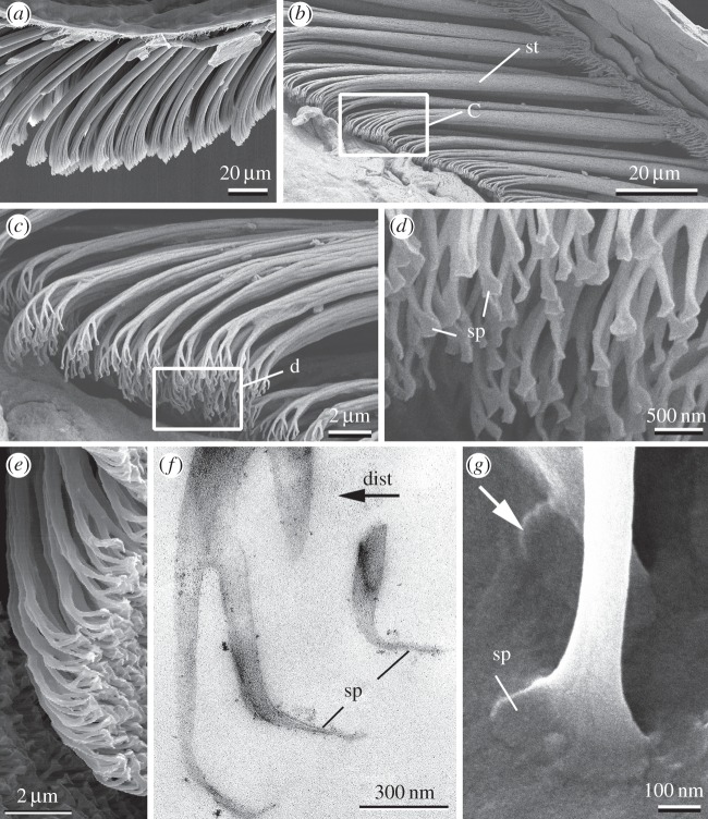
The ventral side of gecko toes bears so-called lamellae with arrays of 3–5 µm thick setae, which are further subdivided at their tips into 100–1000 single nanofibres ending with flattened tips (spatulae) of both width and length of about 200 nm [1–5] and thickness about 15 nm [6] (figure 1). Such subdivision of large adhesive contact into many single separate contacts leads to the enhancement of adhesive force of this fibrillar system for a variety of reasons [7–9]. This effect is also enhanced by the specific spatula-like shape of single contacts [10–12].
Figure 1.
Hierarchical organization of the gecko attachment system: (a) longitudinal section of the gecko toe with the lamella (horizontal thin keratinous film) covered with setae in non-contact state; (b) setae (st) in contact with the substrate; (c,d) setae branching into single nanofibres terminated with spatulae (sp); (e–g) spatulae orientation in a non-contact state (e,f) and contact state (g). White rectangles indicate areas which are zoomed in follow up images. Black arrow (dist) indicates distal direction of the toe in all images in this figure. White arrow shows spatula flipping from non-contact orientation to the contact orientation.
One of the important problems of the synthesis of artificial fibrillar adhesives, inspired by the gecko foot hair, is so-called clusterization [13]. If an artificially produced structure is flexible enough to allow efficient contact with natural rough surfaces, after a few attachment–detachment cycles the fibres of the structure tend to glue one to another and form clusters [14,15]. Normally, such clusters are much larger than original fibres and, owing to their lower flexibility, they form much worse contacts with the surfaces, especially with rough surfaces [8]. Main problem here is that forces responsible for the clusterization are the same intermolecular forces which attract fibres to the uneven surface of the substrate. The optimization between such variables as fibre radius, fibre aspect ratio, material properties and contact shape recently provides an optimal solution, which has been described in a recent paper [16].
However, arrays of real gecko setae are much less susceptible to this problem, in spite of their very high aspect ratio. One of the reasons is that every single seta is a hierarchical structure (figure 1b,c), and each level of such a multilevel architecture is not sensitive to clusterization [17,18]. Another possible reason for low clusterization ability of real setae is that the ends of the seta have more sophisticated non-uniformly distributed three-dimensional structure (figure 1) than that of existing artificial systems [14,15] and than that considered in existing models [18]. In this paper, we simulated three-dimensional spatial geometry of non-uniformly distributed branches of nanofibres of the setal tip numerically, studied its attachment–detachment dynamics and discussed its advantages versus uniformly distributed geometry.
2. Mathematical model
Our discrete numerical model is organized as follows. We describe the dynamics of a set of elastic fibres attached to one wider rigid root fibre, which is initially placed at some angle φt= 0 = φ0 and on some distance from the contact surface. The conceptual structure of the model is shown in figure 2. For definiteness, the number of elastic fibres is equal to 10 Nx = 10, and each fibre is constructed of 50 elastic segments Ny = 50, each having a length of dR = 0.04 µm, to correspond to the total length of each fibre according to the measurements from our scanning electron microscopy (SEM) images (figure 1). The fibres are provided with longitudinal (K||) and transverse (K⊥) stiffness, K|| = K⊥. Transverse stiffness tends to hold the angle between the neighbouring segments close to 180°, and longitudinal one is responsible for its reaction on the extensions along the fibres.
Figure 2.
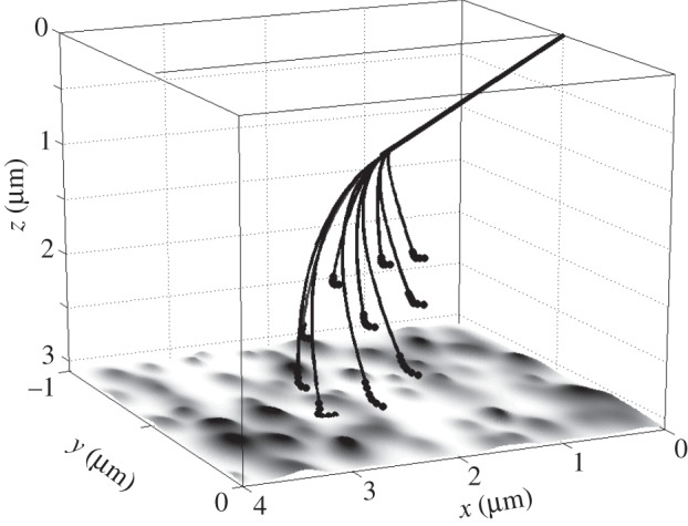
Conceptual three-dimensional structure of the model system. All the segments are numerically defined to mimic real terminal structure of gecko foot hair. Bold straight line corresponds to the root rigid segment (seta). Thin lines reproduce flexible filamentous nanofibres terminated by spatulae. Bold points at the ends of curved lines mark extremely flexible spatula regions. Fractal roughness of the contact substrate is generated according to the standard procedure described in the text and shown by the greyscale in the xy-plane. z-Coordinate of the whole plot is flipped updown, in order not to shadow the filaments by the surface and make easier the perception of the spatial three-dimensional structure. Parameters for modelling were U0 = 10 nN nm, r0 = 0.001 µm, A = r0 and elasticity K = 47.1 mN m−1.
A deformation of fibres produces elastic forces proportional to their stiffness. Longitudinal force,  , is described here by a double-well potential, which is constructed to keep a distance between the nodes Rj and Rj± 1 close to the equilibrium length of the segment dR:
 |
2.1 |
where Rj is a position vector of the middle of the segment (the node) j; k = j ± 1. This form of the equation for the longitudinal force was chosen, because it is linear at small displacement and increases nonlinearly at large displacements. Combination of these two impacts causes a minimum of effective potential at equilibrium length dR.
Second force,  is directly proportional to the lateral deflection and tends to keep Rj close to the mean value between its nearest neighbours, (Rj± 1 + Rj− 1)/2:
| 2.2 |
It must be noted that the ‘transverse’ force  is chosen in the present form because it is easy to realize numerically, in order to prevent bending of the fibres, but it is not purely bending force, because it may include a longitudinal component.
We construct the initial structure of the fibres in a manner to mimic as much as possible the form of such a structure of a real animal shown in figure 1. Each of the fibres is elastically attached to the rigid root fibre (bold straight line in the conceptual image). The fibres have different lengths and orientations. As result, their ends are shifted one from another in three directions: parallel to the line of the root and in two orthogonal directions. To mimic better the natural structure, we generated individual initial positions of every single segment numerically. Resulting configuration is shown in the conceptual image (figure 2). It reproduces also a correct orientation of the terminal parts (spatulae) of the fibres, which are turned backward to the root in equilibrium gecko hair.
According to the main hypothesis of this study, different positions of the fibre ends of the realistic fascicle-like spatial structure of the seta and its orientation to the surface are important for the functional efficiency of the structure. So, our aim was to study how attachment scenario depends on the three-dimensional configuration and as a result, how practically important parameters (fraction of attached spatulae, and tendency to clusterization at an equilibrium) correlate with the three-dimensional spatial structure of the seta.
In a real system, an additional degree of freedom comes from the rotation of the relatively rigid root fibre. To reproduce it in the model, rotational stiffness, B, is introduced, which dynamically tends to keep the root angle φ close to φ0. In the first approximation, the rotational force acting on it is linearly proportional to the difference φ0 − φ:
| 2.3 |
At B greater than 0, the force in equation (2.3) tends to attract the angle φ to its equilibrium value φ0. As a result, the whole system rotates towards the substrate, when the fibres are attracted to it. If a force between the surface and the fibres is absent, the system gradually returns to a shape close to the initial one depicted in figure 2.
Real surfaces of the substrates, where the fibres attach to, have semi-fractal structure with well-known Fourier spectrum and amplitude of roughness. It can be simulated by the self-affine fractal given by the real part of the function
| 2.4 |
with scaling spectral density C(q). Here, A is amplitude of surface roughness, i is imaginary unit, qx,y are Fourier components along x- and y-directions,  and ζ(x, y) is a δ-correlated random phase. Details of the generation procedure for the profile Z(x, y) have been described in a number of previous papers [19–21]. In the current literature [6], it is accepted that majority of physical surfaces have scale-invariant spectrum C(q) = 1/qβ with exponent β ≈ 0.9.
The attraction to the surface is caused by an intermolecular (van der Waals) force. For the sake of simplicity, we simulate it by the gradient of Morse potential
| 2.5 |
where rj = |rj− Z(x, y)| with physically reasonable amplitude U0 = 10 nN nm and the minimum located at the distance r0 = 0.001 µm from the surface. The amplitude of the numerically generated surface is taken to be comparable to the radius of van der Waals interaction A = r0.
Flexible and thin parts of every fibre interact with corresponding regions of other fibres of the array. Interaction force has the same origin as their attraction to the stiff substrate Uinteract(r) = U0(1 − exp(−rjk/r0))2 and comparable characteristic parameters U0,r0. For simplicity of the model, we reduce mutual interaction of the fibres by the interaction of the nearest neighbours: rjk = |rj − rj±1|. This force is responsible for the clusterization of the fibre structure, and our goal here is to study whether specific spatial distribution of the fibres can prevent it.
Our numerical experiment is organized as follows. We place fascicle-like seta in the position where distance from the last segment (closest to the surface) is comparable to r0 and allow it to move according to standard equations of motion
| 2.6 |
where total force accumulates all above interactions  .
.
When the process starts, a closest segment is normally attracted to the surface first (electronic supplementary material, movies 1 and 2). Owing to mutual elastic and molecular interactions with all other segments, it tends to cause consequent attraction of all of them. From the other side, all the segments are attached to the root and transfer the interaction to it. Being rigidly fixed by one of its ends at zero point, this segment can not only completely move with all other ones, but it also can rotate to minimize a distance between its free end and the surface.
3. Results and discussion
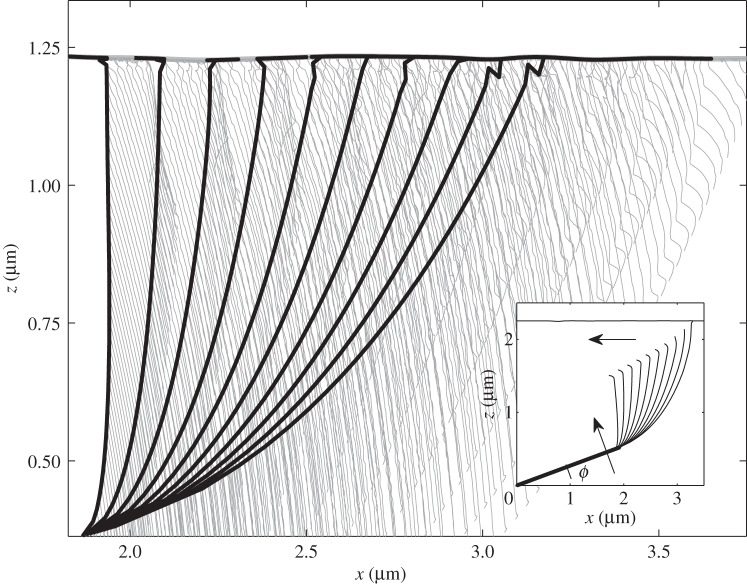
To simplify visualization and plotting of the results, let us first discuss this process for reduced two-dimensional system, which moves in the {x, z}-plane. In this case, instant positions of the segments at some discrete time moments, as well as trajectories of all the joint points connecting the segments, can be simultaneously depicted in a quite transparent planar plot. Typical scenario of the motion is presented in figure 3 (electronic supplementary material, movie 1), where instant positions and the trajectories are shown by black and grey lines, respectively.
Figure 3.
Conceptual picture of the model in two-dimensional plane {x, z}. The fibres and their trajectories are shown by bold black and thin grey lines, respectively. Initial configuration is presented in the inset. The arrows show additional directions of the motion, which appear owing to the attraction of the fibres to the surface: rotation of the rigid root (seta) and shear along x-coordinate. Parameters for modelling were U0 = 10 nN nm, r0 = 0.002 µm, A = r0 and elasticity K = 47.1 mN m−1.
Rotation of the root segment is the key difference between this scenario and ordinary attraction of regular grid of vertical fibres. As is seen directly from figure 3, this rotation leads to a directed proximal shift of the attachment point along the surface and results in an effective healing effect. In other words, additionally to the vertical attraction to the surface, all the fibres simultaneously slightly move along it. Previously, it was experimentally and theoretically demonstrated that such shear movements applied to the spatulae enhance adhesion of thin tapes [2,12].
Such a motion must have an important effect in the real biological system, because it automatically stimulates more efficient increase of a fraction of the attached spatulae in contact process, and most importantly it does not require active control by the animal. In addition, it is important to note that owing to this process all terminal spatulae turn oppositely to the direction of motion. When they attach to the surface by their very tips, shear motion shifts them against already established contact points. As a result, the spatulae flip around them. This rotation produces typical configurations that are clearly seen in SEM images of real gecko hairs attached to the surface (figure 1g), where spatulae are usually turned in one direction, which is opposite to their original orientation (figure 1e,f).
As mentioned above, mutual shift of the spatulae in vertical direction should prevent their clusterization after detachment from the surface. The main problem, causing clusterization, is that spatulae tend to attract to the same regions of the surface (mainly to the asperities protruding from the surface into direction of the fibres). When the fascicle of the nanofibres starts to detach from the surface, the nearest fibres are located already close to one another and will remain attracted even after complete detachment. As a result, in further attachment cycles, the whole system becomes already modified by the preliminary process, and will not operate properly.
The three-dimensional spatial configuration of the seta with its branches of nanofibres and terminal spatulae has been optimized by natural selection. Our numerical experiment confirms intuitive expectation that if flexible ends of the nanofibres are shifted one from another in the vertical direction, stored elastic energy, tending to return them to their original position, easily separates them. On the other side, at given trial angle φ0, very strong shift of some of the fibres in vertical direction must prevent their attachment to the surface. It leads to a formal problem of optimization.
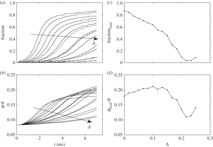
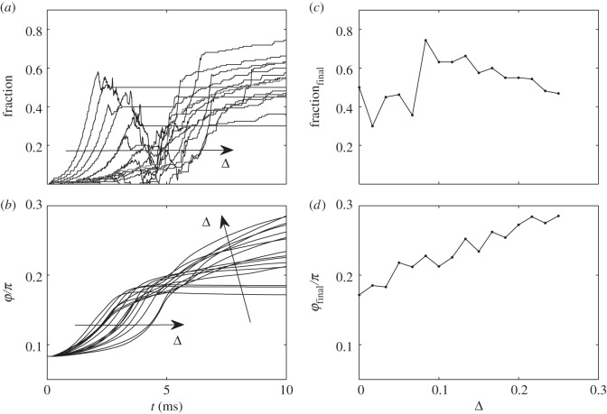
To solve this problem, we compared numerical solution of the equations of motion equation (2.4) with and without mutual interaction between the fibres. The results are summarized in figures 4 and 5, respectively, where time-depending fraction of the attached nanofibres and rotation angle φ are presented together with their final values at different shift Δ (dimensionless value which corresponds to the difference between maximal and minimal length of the fibres normalized to their maximal length). In the case of the non-interacting fibres, the results are quite trivial. The fraction of the attached fibres gradually decreases with the shift Δ. Time-depending behaviour of the angle φ is also quite predictable here. When the very first fibres attach to the surface, the angle φ starts to grow. Elasticity works against this rotation and in principle stops the angle φ at some final value at t → ∞. If the upper fibres are strongly shifted in vertical direction, they do not participate in the attraction, and it prevents the rotation as well. The final angle φ at t → ∞ is defined by a balance of the forces caused by the very few attached lowest fibres and falls down at some shift Δ.
Figure 4.
Time-depending fraction of the attached fibres and angle φ for non-interacting fibres, reproduced in the subplots (a) and (b), respectively. Final values of the fraction and angle, calculated at different shift Δ, are shown in the subplots (c) and (d), respectively. The tendencies with variation of Δ in the time-depending plots are marked by the arrows.
Figure 5.
Time-depending fraction of the attached fibres and angle φ for interacting fibres, reproduced in the subplots (a) and (b), respectively. Final values of the fraction and angle, calculated at different shift Δ, are shown in the subplots (c) and (d), respectively. The tendencies with variation of Δ in the time-depending plots are marked by the arrows.
Quite a different picture appears, when the fibres interact. The system demonstrates some clear optimum Δ, clearly seen in figure 5. The main reason for it is that for very small shift Δ → 0 the fibres attract one to another in the space over the surface and tend to build clusters. Such clusterization reduces their attachment ability to the substrate. In the other limit, when Δ → ∞, obviously, the interaction of the fibres becomes weaker and attachment fraction decreases. However, as we found from the numerical experiment, attraction of the upper fibres to the attached ones still favours the rotation, and the final angle φ grows.
One of the important disadvantages of the two-dimensional model is that it does not reproduce a distance between the spatulae in the y-direction orthogonal to the rotation plane {x, z}. However, this coordinate becomes extremely important when all the fibres contact the surface. As mentioned above, rotation of the structure leads to the effect of shear, which aligns all the spatulae in one direction. As result, in many places, they formally overlap on the surface and their mutual attraction and, respectively, a tendency to the clusterization becomes overestimated by the two-dimensional model.
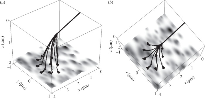
In reality, they are moved apart, as is shown in the conceptual three-dimensional picture (figure 2) in the {x,y} projection and remain separated, when they come in contact with the substrate (electronic supplementary material, movie 2). Moreover, numerical experiments show that the specific configuration of forces, which appears in the particular system in contact process, turns the spatula {x,y}-plane to the opposite radial orientation around a common point, where all of them remain attached to the root segment. Two different views on typical final attached configuration are shown in figure 6a,b. Being separated even on the surface, the spatulae can easily return to their initial positions shown in figure 2. This effect prevents their clusterization and allows practically infinite number of repeats of the attachment–detachment cycles.
Figure 6.
Two different views of the same attached configuration of the modelled seta, shown in isometric and almost vertical projections in subplots (a) and (b), respectively. All symbols are the same as in figure 2.
Overall, this model shows that in addition to the hierarchical organization of the seta [17,18], its non-symmetric structure and non-uniform distribution of nanofibres lead to the preventing of clusterization. Such a sophisticated non-uniformly distributed three-dimensional structure additionally provides rotation-induced proximal shear of spatulae, which is crucial for contact formation of spatulae and formation of adhesive contact in thin tapes [12]. Because these effects are entirely based on particular geometry of the seta, it certainly would have practical application, owing to simple, purely mechanical, effect for the enhancement of the performance of artificially made fibrillar adhesives.
Acknowledgements
We thank Alexander Kovalev (Kiel University, Germany) for fruitful discussions and his help with the estimation of the stiffness of setal branches.
Funding statement
This work was supported by German Science Foundation (DFG, no. GO 995/10-1 and project no. C-10 within SFB 677) and by the EU COST Action TD0906 ‘Biological adhesives: from biology to biomimetics’.
References
- 1.Hiller U. 1968. Untersuchungen zum Feinbau und zur Funktion der Haftborsten von Reptilien. Z. Morphol. Tiere 62, 307–362. ( 10.1007/BF00401561) [DOI] [Google Scholar]
- 2.Autumn K, Liang YA, Hsieh ST, Zesch W, Chan WP, Kenny TW, Fearing R, Full RJ. 2000. Adhesive force of a single gecko foot-hair. Nature 405, 681–684. ( 10.1038/35015073) [DOI] [PubMed] [Google Scholar]
- 3.Autumn K, et al. 2002. Evidence for van der Waals adhesion in gecko setae. Proc. Natl Acad. Sci. USA 99, 12 252–12 256. ( 10.1073/pnas.192252799) [DOI] [PMC free article] [PubMed] [Google Scholar]
- 4.Huber G, Gorb SN, Spolenak R, Arzt E. 2005. Resolving the nanoscale adhesion of individual gecko spatulae by atomic force microscopy. Biol. Lett. 1, 2–4. ( 10.1098/rsbl.2004.0254) [DOI] [PMC free article] [PubMed] [Google Scholar]
- 5.Rizzo NW, Gardner KH, Walls DJ, Keiper-Hrynko NM, Ganzke TS, Hallahan DL. 2006. Characterization of the structure and composition of gecko adhesive setae. J. R. Soc. Interface 3, 441–451. ( 10.1098/rsif.2005.0097) [DOI] [PMC free article] [PubMed] [Google Scholar]
- 6.Persson BNJ, Gorb SN. 2003. The effect of surface roughness on the adhesion of elastic plates with application to biological systems. J. Chem. Phys. 119, 11 437–11 444. ( 10.1063/1.1621854) [DOI] [Google Scholar]
- 7.Arzt E, Gorb S, Spolenak R. 2003. From micro to nano contacts in biological attachment devices. Proc. Natl Acad. Sci. USA 100, 10 603–10 606. ( 10.1073/pnas.1534701100) [DOI] [PMC free article] [PubMed] [Google Scholar]
- 8.Persson BNJ. 2003. On the mechanism of adhesion in biological systems. J. Chem. Phys. 118, 7614–7621. ( 10.1063/1.1562192) [DOI] [Google Scholar]
- 9.Varenberg M, Pugno NM, Gorb SN. 2010. Spatulate structures in biological fibrillar adhesion. Soft Matter 6, 3269–3272. ( 10.1039/c003207g) [DOI] [Google Scholar]
- 10.Gao H, Yao H. 2004. Shape insensitive optimal adhesion of nanoscale fibrillar structures. Proc. Natl Acad. Sci. USA 101, 7851–7856. ( 10.1073/pnas.0400757101) [DOI] [PMC free article] [PubMed] [Google Scholar]
- 11.Spolenak R, Gorb S, Gao H, Arzt E. 2005. Effects of contact shape on the scaling of biological attachments. Proc. R. Soc. A 461, 305–319. ( 10.1098/rspa.2004.1326) [DOI] [Google Scholar]
- 12.Filippov AE, Popov VL, Gorb SN. 2011. Shear induced adhesion: contact mechanics of biological spatula-like attachment devices. J. Theor. Biol. 276, 126–131. ( 10.1016/j.jtbi.2011.01.049) [DOI] [PubMed] [Google Scholar]
- 13.Jagota A, Bennison SJ. 2002. Mechanics of adhesion through a fibrillar microstructure. Integr. Comp. Biol. 42, 1140–1145. ( 10.1093/icb/42.6.1140) [DOI] [PubMed] [Google Scholar]
- 14.Northen MT, Turner KL. 2005. A batch of fabricated dry adhesive. Nanotechnology 16, 1159–1166. ( 10.1088/0957-4484/16/8/030) [DOI] [Google Scholar]
- 15.Yurdumakan B, Raravikar NR, Ajayan PM, Dhinojwala A. 2005. Synthetic gecko foot-hairs from multiwalled carbon nanotubes. Chem. Commun. 3799–3801. ( 10.1039/b506047h) [DOI] [PubMed] [Google Scholar]
- 16.Spolenak R, Gorb S, Arzt E. 2005. Adhesion design maps for bio-inspired attachment systems. Acta Biomater. 1, 5–13. ( 10.1016/j.actbio.2004.08.004) [DOI] [PubMed] [Google Scholar]
- 17.Bhushan B, Peressadko AG, Kim TW. 2006. Adhesion analysis of two-level hierarchical morphology in natural attachment systems for ‘smart adhesion’. J. Adhes. Sci. Technol. 20, 1475–1491. ( 10.1163/156856106778666408) [DOI] [Google Scholar]
- 18.Kim TW, Bhushan B. 2007. Effect of stiffness of multilevel hierarchical attachment system on adhesion enhancement. Ultramicroscopy 107, 902–912. ( 10.1016/j.ultramic.2006.11.008) [DOI] [PubMed] [Google Scholar]
- 19.Filippov AE, Popov VL. 2007. Fractal Tomlinson model for mesoscopic friction: from microscopic velocity-dependent damping to macroscopic Coulomb friction. Phys. Rev. E 75, 027103 ( 10.1103/PhysRevE.75.027103) [DOI] [PubMed] [Google Scholar]
- 20.Filippov AE, Popov VL. 2007. Flexible tissue with fibres interacting with an adhesive surface. J. Phys. Condens. Matter 19, 096012 ( 10.1088/0953-8984/19/9/096012) [DOI] [Google Scholar]
- 21.Popov VL, Starcevic J, Filippov AE. 2007. Reconstruction of potential from dynamic experiments. Phys. Rev. E 75, 066104 ( 10.1103/PhysRevE.75.066104) [DOI] [PubMed] [Google Scholar]


