Abstract
Objective(s). The major challenge encountered to decrease the milliamperes (mA) level in X-ray imaging systems is the quantum noise phenomena. This investigation evaluated dose exposure and image resolution of a low dose X-ray imaging (LDXI) prototype comprising a low mA X-ray source and a novel microlens-based sensor relative to current imaging technologies. Study Design. A LDXI in static (group 1) and dynamic (group 2) modes was compared to medical fluoroscopy (group 3), digital intraoral radiography (group 4), and CBCT scan (group 5) using a dental phantom. Results. The Mann-Whitney test showed no statistical significance (α = 0.01) in dose exposure between groups 1 and 3 and 1 and 4 and timing exposure (seconds) between groups 1 and 5 and 2 and 3. Image resolution test showed group 1 > group 4 > group 2 > group 3 > group 5. Conclusions. The LDXI proved the concept for obtaining a high definition image resolution for static and dynamic radiography at lower or similar dose exposure and smaller pixel size, respectively, when compared to current imaging technologies. Lower mA at the X-ray source and high QE at the detector level principles with microlens could be applied to current imaging technologies to considerably reduce dose exposure without compromising image resolution in the near future.
1. Introduction
With all other technical factors (e.g., kilovolts, distance, time, etc.) held constant, patient radiation dose is directly proportional to the milliamperes (mA). A 50% reduction in mA would result in a decrease in radiation dose by 50% [1]. Previously, the mA range has not been taken into consideration in any attempt to reduce radiation dose to which dental patients are being exposed [2–6]. The sensitivity of a digital sensor is measured at a constant wavelength in nanometers (nm) on the basis of the detective quantum efficiency (DQE). This value is used primarily to describe imaging detectors in optical imaging and medical radiography [7]. The quantum efficiency (QE) is the ratio of impinging photons on a pixel to the number of collected electrons. The QE of the pixel is equal to the QE of the complementary metal oxide semiconductor (CMOS) photodiode multiplied for the fill factor of the pixel [8]. Fluoroscopy is a dynamic X-ray or X-ray movie showing images of video frame rates produced by a low mA X-ray source and image intensification at the detector level [9]. An image intensifier unit is capable of multiplying 1,000 to 20,000 times, electron-by-electron, of the produced image, therefore increasing the system QE while allowing dose reduction [10, 11]. Unfortunately, image intensifier units and direct radiography large flat panel detectors have heretofore been too bulky to be used inside the mouth as well as being expensive for a dental setting [12–14]. Another disadvantage of intensifiers is image distortion [15]. With regard to visualization of a stent created from 50 microns (μm) diameter wires in flat panel X-ray fluoroscopy, for the idealized direct detector, the 100 μm pixel size resulted in maximum measured contrast sensitivity. For an idealized indirect detector, with a scintillating layer, the maximal measured contrast sensitivity was obtained at 200 μm pixel size [16].
The major challenge encountered to decrease the mA level in X-ray imaging systems is the quantum noise phenomena. In electronic imaging systems such as fluoroscopy or intraoral radiography digital sensors, we find three principal sources of noise. The first and most relevant arises from quantum statistics, in which the discrete nature of the radiographic signal (which often is photon-starved) introduces uncertainty into the image. The second is electronic noise which is generated in the detector or detector electronics. The third is quantization error that occurs in digital electronic imaging systems when the signal is digitized. For a quantum statistics noise limited system, if the number of photons used is quadrupled, the noise in the resultant image should be halved [17–20]. Not only X-ray systems but also digital cameras are noise limited and quantum limited. Randomly spaced speckles, called noise, can appear in digital images. Noise is similar to grain that appears in photos taken with traditional cameras using high International Organization of Standardization (ISO) films. Noise increases in photos taken with a digital camera using a high ISO number. The higher ISO number leads to more noise. When noise is present, image detail and clarity are reduced, sometimes significantly. The ISO level indicates the film and digital camera's sensitivity to light. According to the ANSI/ISO classification, a dental film with raw speed of ISO 29–56 would be classified as E speed, while one with speed of ISO 57–112 would be classified as F speed [21]. Photographic film typically has a QE of much less than 10% [22]. Current digital cameras have improved their ISO settings which can achieve up to ISO 204,800 [23–25]. To improve the sensitivity or QE of front illuminated charged couple device (CCD) and CMOS image sensors without increasing their pixel size, digital cameras manufacturers apply a thin (0.5–1.0 mm thickness) and inexpensive microlens array to the sensors to reach high ISO levels [26]. The microlens principle was invented in the 17th century where Hooke and Van Leeuwenhoek developed techniques to make small glass lenses for use with their microscopes [27]. The microlens collects and focuses light that would have otherwise fallen onto the nonsensitive areas of the sensor chip, improving the QE significantly (Figure 1) [28].
Figure 1.
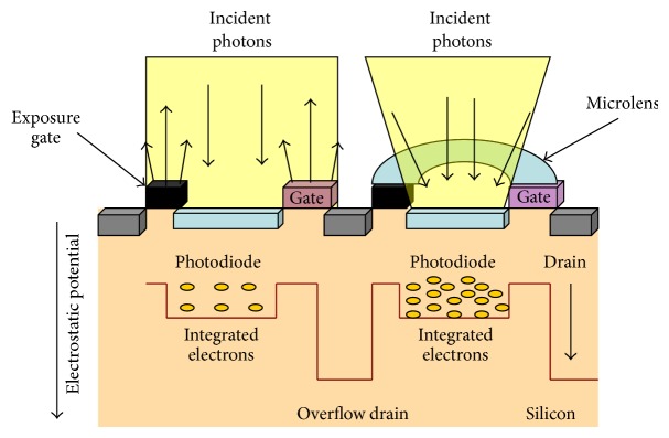
CMOS sensor and microlens (right side) architecture scheme.
Attempts for improving digital sensors QE without compromising the system's noise have been made through the introduction of back illuminated and electron multiplied CCD and CMOS image sensors. Their major drawbacks are complicated manufacturing processes and elevated cost [29, 30]. As a result, the most common used image sensor in dentistry is the front illuminated type [31].
Consequently, a lower milliamperes (mA) setting at the X-ray source and the use of front illuminated sensors with microlens or back illuminated sensors at the detector level for an increased QE that reduces the required radiation dose and sensor pixel size without impacting image quality should have a dramatic positive impact on dental radiology and oral diagnosis. The purpose of this investigation was to prove the concept of radiation exposure reduction and dynamic fluoroscopy feasibility in dentistry without compromising image quality by testing a low-dose X-ray imaging (LDXI) prototype comprising a low-dose X-ray source and a high QE front illuminated sensor with microlens and comparing it to standard of care in terms of dose exposure in milligrays (mGy) and image resolution in lines per millimeters (lp/mm) [6].
2. Materials and Methods
The Temple University Environmental Health and Radiation Safety Institutional Department approved this study. A LDXI prototype (Real Time Imaging Technologies, LLC, Cleveland, OH) was used. The LDXI was comprised of a 35–80 kilovolt peak (kVp), 0.1–0.5 mA X-ray source (9.95′ L × 5.27′ W × 5.35′ H) (SourceRay, Bohemia, NY), and a 8′ rectangular collimator (Margraf Dental, Jenkintown, PA) and an X-ray detector utilizing a CMOS front illuminated sensor (EOS 5D Mark III, Canon, Japan) having 36 × 24 mm effective area, 6.25 × 6.25 um pixel size, 22.3 megapixels resolution, and 49% [32] QE with microlens and capable of performing up to 30 frames per second (fps) for the dynamic video mode. The CMOS sensor modular transfer function (MTF) was >30% at the 18 lp/mm range. Upon low-pass filter and sensor removal, the scintillator/fiber optic plate (AppliedScintech, UK) was coupled at the sensor [33, 34] on top of the microlens [35] with optic glue (BEW Engineering, Ketsch, Germany). The scintillator/fiber optic plate measured 20.8 × 20.8 mm and was comprised of a 6 um columnar cesium iodide with thallium (CsI : TI) coating with a MTF curve showing and ultimate resolution >18 lp/mm at 60 kVp with 98% attenuation at 70 kVp. Camera software (EOS Utility Ink, Japan) and a kid's watch (Disney Store, Orlando, FL) were used in order to establish and calibrate sensor's ISO settings. Images obtained were raw positive still shots and video. Raw images (A) were converted to negative radiographic images (B) through a software and then cropped (Microsoft Digital Suite 2006 Editor, Microsoft, Redmond, WA) (Figure 2).
Figure 2.
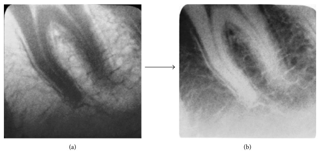
(a) Molar tooth raw positive image obtained at 0.2 mA and 1/30 camera shutter (0.03 seconds) with collimation and (b) negative image.
Ionization chambers Radcal 9010 (Radcal Corp., Monrovia, CA) and RaySafe Xi (RaySafe, Hopkinton, MA) were used to measure the dose exposure in mGy (obtained through rad formula conversion) received by a patient phantom (DXTTR, RINN, Elgin, IL) in all groups and sixteen dosimeters (Landauer, Inc., Glenwood, IL) were utilized for obtaining the dose equivalent in millisievert (mSv) (obtained through rem formula conversion) received by the operator simulated distance at 30 cm for LDXI and fluoroscopy (Figure 3).
Figure 3.
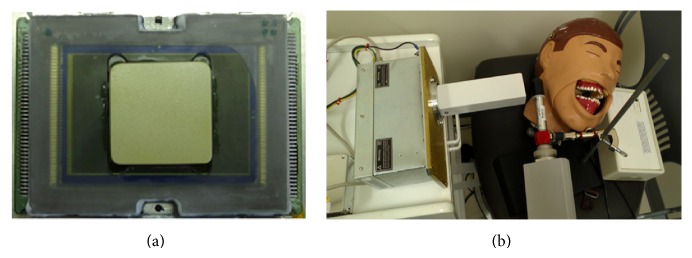
(a) Dental size sensor with microlens coupled with scintillator/FOP (front view) and (b) LDXI prototype testing on the DXTTR phantom at 0.2 mA and 80 kVp.
ISO settings were established at ISO 5,000 for group 1 and ISO 12,800 for group 2 and image acquisition was made at 1/30 shutter (0.03 seconds). Group 1 was exposed to the LDXI prototype (Real Time Imaging Technologies, LLC, Cleveland, OH) at 0.2 mA and 80 kVp in static mode during 10 intervals from 0 to 27 continuous seconds with a 6.25 × 6.25 um pixel size sensor and 49% QE. Group 2 was exposed to the LDXI prototype at 0.2 mA and 80 kVp in the dynamic video mode during 31 intervals from 0 to 300 seconds with a 6.25 × 6.25 um pixel size sensor and 49% QE. Group 3 was exposed to medical fluoroscopy (GE C-arm OEC 9800, Cleveland, OH) at 0.038 mA and 55 kVp in 31 intervals from 0 to 300 seconds with a 12.8 × 12.8 um pixel size sensor and a 9′ image intensifier with 65% QE at 550 nm [36]. Group 4 was exposed to digital intraoral radiography (Gendex GX-770, Hatfield, PA/Planmeca Dixi 2 v3, Roselle, IL) at 7 mA and 70 kVp in 29 intervals from 0 to 1.65 seconds with a 19 × 19 um pixel size sensor. Group 5 was exposed to CBCT Scan (iCat Imaging Sciences International Inc., Hatfield, PA) at 5 mA and 120 kVp from 0 to 26.9 seconds in 28 intervals and several modalities with a 125 um voxel size sensor. Six thermoluminescent Luxel and ten optical stimulated luminescence technology Nanodots dosimeters (Landauer, Inc., Glenwood, IL) were used at the patient phantom, area monitor, and positive and negative controls for the LDXI. After research completion, all the dosimeters were mailed back to Landauer for analysis purposes. Image resolution for the LDXI was measured with a resolution test pattern (Fluke Corp., Cleveland, OH) in lp/mm. An endodontic file size 10 (Dentsply, Maillefer, York, PA) was placed within phantom's tooth number 27 at the radiographic apex for intraoral imaging subjective resolution assessment purposes in which two endodontists and one oral and maxillofacial radiologist from the institution were asked to confirm tooth's working length [6]. Dose exposure measurements and image resolution were calculated for all groups and dosimeters were analyzed.
3. Results
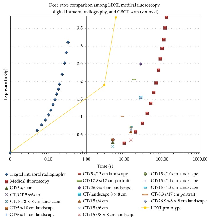
The Mann-Whitney test showed no statistical significance (α = 0.01) in dose exposure (mGy) between groups 1 and 3 and 1 and 4 and timing exposure (seconds) between groups 1 and 5 and 2 and 3 (Figure 4).
Figure 4.
Radiation and timing exposures comparison amongst all groups.
Dosimeters for the LDXI operator simulated distance and controls did not register significant dose equivalent (mSv).
Image resolution test showed LDXI 1 > digital intraoral radiography > LDXI 2 > medical fluoroscopy > CBCT scan (Table 1).
Table 1.
mA, kVp, pixel size settings, and resolution outcome comparison of different devices.
| Device type | mA | kVp | Pixel/voxel size (um) |
Resolution (lp/mm) |
|---|---|---|---|---|
| LDXI 1 (static) | 0.2 | 80 | 6.25 × 6.25 | 18 |
|
| ||||
| LDXI 2 (dynamic) | 0.2 | 80 | 6.25 × 6.25 | 10 |
|
| ||||
| Medical fluoroscopy (image intensified) | 0.038 | 55 | 12.8 × 12.8 | 1.75 |
|
| ||||
| Digital intraoral radiography | 7 | 70 | 19 × 19 | 16 |
|
| ||||
| CBCT scan | 5 | 120 | 125 | 1.6 |
File size 10 was observed at the working length as confirmed by two endodontists and one oral and maxillofacial radiologist (Figure 5).
Figure 5.
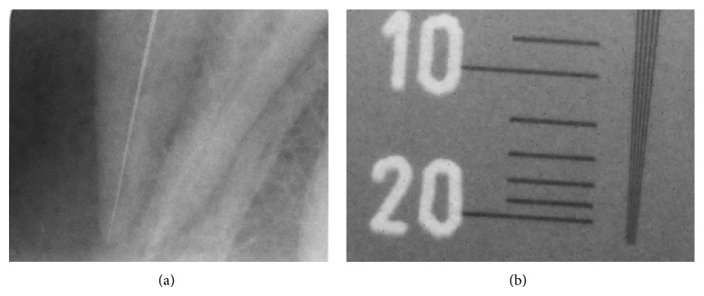
Group 1 LDXI static: (a) endodontic file number 10 at working length and (b) 18 lp/mm.
4. Discussion
Technical advances enable cameras to better capture the drama of low-light photography/video. As a rule, bigger is indeed better when it comes to the overall dimensions of a sensor because a bigger sensor provides not only more pixels, but also bigger pixels, which more efficiently gather light. However, of all the improvements in the imaging field, perhaps the most notable are not the increases in sensor size but the innovations in increasing a sensor's ability to gather light in low-light situations and to record a wider range of light. Much improved sensors with microlens now allow one to obtain detailed low-light images by allowing shots at high ISO levels that previously generated unflattering digital “noise” or graininess in an image at smaller pixel sizes. From an image resolution dental perspective, studies have demonstrated that spatial resolution affects bone loss and caries diagnosis in dentistry. A research undertaken to determine the effect of X-ray beam alignment and spatial resolution on quantification of alveolar bone using radiometric techniques concluded that 50 um pixel spatial resolution is apparently superior to 200 um pixel images if radiometric data is to be evaluated [37]. Another study determined that spatial resolution affected radiometric analyses aimed at detecting progressive enamel loss. Cumulative percent histograms shifts associated with the smaller 59 um pixels accounted for 68% of the variation in weights caused by enamel reduction, whereas the shifts associated with the larger 200 um pixels accounted for 50%. The results indicated that pixel size does affect radiometric determinations of enamel reduction [38, 39]. In summary, the smaller the pixel size and the more pixels are arranged in a sensor, the better the quality of the image that is captured. In this study, microlens also allows decreasing the sensor's pixel size (6.25 × 6.25 um), therefore increasing image spatial resolution as compared to the larger pixel size of current sensors used in digital intraoral radiography (19 × 19 um), CBCT scans (125 um voxel), and medical fluoroscopy (12.5 × 12.5 um for image intensifiers and 100 × 100 um for flat panel detectors). As compared to similar front illuminated intraoral sensors used in dentistry (DQE 3% CCD and DQE 18% CMOS) [40, 41] the LDXI prototype has used a large size (35 mm), full frame, and front illuminated CMOS sensor with a thin microlens array for improved DQE (49%) directly coupled to the scintillator/fiber optic plate, capable of acquiring low mA images at ISO 5,000 and ISO 12,800 as well as in dynamic video frame rates. From a radiation exposure perspective, we found that 3.05 and 3.95 seconds of LDXI are comparable to one single shot of 0.2 seconds of digital intraoral radiography and 26.9 seconds 4 cm landscape single area CBCT scan, respectively. As a result, the LDXI used for 0.2 seconds would reduce 93.4% dose exposure as compared to digital intraoral radiography used for 0.2 seconds. For a conventional root canal requiring a pre-op, working length, master cone, partial condensation, and final X-ray, the LDXI prototype could be used during 15 seconds without producing more dose exposure due to the addition of microlens for increased QE as compared to digital intraoral radiography. As a result, lower mA settings (up to 0.2 mA) as compared to digital intraoral radiography (7 mA) could be captured at 18 lp/mm and 10 lp/mm image resolution for the static and dynamic modalities, respectively [6]. In addition, an endodontic file size 10 was observed at the working length at the phantom as confirmed by two endodontists and one oral and maxillofacial radiologist from the institution (Figure 5). In addition to root canals, other clinical applications for low dose X-ray sources and high QE image sensors in the static mode would be full mouth X-rays, pre- and postradiographs, bitewings, and panoramic, cephalometric, and CBCT scans for oral diagnosis while the dynamic mode would allow the introduction of fluoroscopy in dentistry for dental implant placement, temporomandibular joint analysis, maxillofacial surgeries, and postplacement. Since the scintillator/fiber optic plate was coupled in the central area of the sensor, the effect of X-rays on the surrounding, residual, and uncovered area caused significant noise causing black spots at the image. In addition, despite the fact that sensor's housing was internally masked against light, light pollution was observed on one corner (Figure 6).
Figure 6.
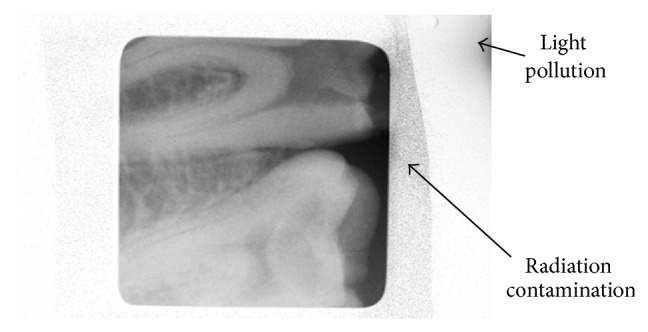
Preventable artifacts obtained in images.
These artifacts should be avoided in future studies by providing complete sensor shielding and a 100% light proof housing. In addition to further evaluations with higher QE (>65% at 550 nm) new generation front illuminated sensors with microlens, the authors recommend testing a back illuminated sensor due to its increased QE as compared to the front illuminated sensor used in this study [14, 35]. Finally, we propose testing the next generation LDXI using head and neck anthropomorphic phantoms following Sections C and D of the FDA guidance for Solid State X-Ray Imaging Devices (MTF, detective quantum efficiency, and signal-to-noise ratio) and compare it to digital intraoral radiography, medical fluoroscopy, and CBCT scan imaging devices.
5. Conclusions
The LDXI proved the concept for obtaining a high definition image resolution for static and dynamic radiography at lower or similar dose exposure and smaller pixel size, respectively, when compared to traditional imaging devices. Lower mA at the X-ray source and high QE at the detector level principles with microlens could be applied not only to digital intraoral radiography and dental fluoroscopy but also to panoramic, cephalometric, and CBCT scans devices to considerably reduce X-ray source dose exposure as well as sensor pixel size and more research is recommended to demonstrate this further.
Acknowledgments
This study has been possible thanks to the funds received by Real Time Imaging Technologies, LLC (Cleveland, OH), from the Great Lakes Innovation & Development Enterprise Grant ($25,000) and the Indus Entrepreneurs (TiE) Ohio Business Plan Competition Award ($2,500) as well as by the research team from Temple University Kornberg School of Dentistry Student Research Grant ($2,000).
Diclosure
The paper, or any part of it, has not been submitted or published and will not be submitted elsewhere for publication while being considered by the journal. The research has been shown as a poster presentation at Temple University Kornberg School of Dentistry Research Day and has been presented at the 64th AAOMR Annual Session as an abstract and as part of the 2013 William H. Rollins Award Lecture.
Conflict of Interests
Jie Yang is a consultant to and Daniel Uzbelger Feldman has equity interest in Real Time Imaging Technologies, LLC. Arnav R. Mistry and Eric Ryterski had no conflict of interests. At the time this study was conducted, Arnav R. Mistry was an endodontology postgraduate student at Temple University Kornberg School of Dentistry.
References
- 1.Carroll Q. B. Fuchs’s Radiographic Exposure and Quality Control. 7th. Charles C Thomas Publisher; 2003. [Google Scholar]
- 2.Uzbelger D. Comparison between medical fluoroscopy, digital dental imaging and intraoral radiography. Journal of Dental Research. 2005;97:701. [Google Scholar]
- 3.Uzbelger-Feldman D., Susin C., Yang J. The use of fluoroscopy in dentistry: a systematic review. Oral Surgery, Oral Medicine, Oral Pathology, Oral Radiology, and Endodontology. 2008;105, article e61 [Google Scholar]
- 4.Uzbelger Feldman D., Yang J., Susin C. A systematic review of the uses of fluoroscopy in dentistry. The Chinese Journal of Dental Research. 2010;13(1):23–29. [PubMed] [Google Scholar]
- 5.Uzbelger Feldman D., Panchal P. M., Yang J. Resolution and dose rates comparison among fluoroscopy, digital/film-based intraoral radiography and CBCT scan. Proceedings of the 61th Annual Meeting of the American Academy of Oral & Maxillofacial Radiology; 2010; San Diego, Calif, USA. [Google Scholar]
- 6.Uzbelger Feldman D., Mistry A., Yang J. Radiation exposure and image resolution testing of a low-dose X-ray imaging. Proceedings of the 64th Annual Meeting of American Academy of Oral & Maxillofacial Radiology; October 2013; Beverly Hills, Calif, USA. [Google Scholar]
- 7.Cowen A. R., Davies A. G., Sivananthan M. U. The design and imaging characteristics of dynamic, solid-state, flat-panel x-ray image detectors for digital fluoroscopy and fluorography. Clinical Radiology. 2008;63(10):1073–1085. doi: 10.1016/j.crad.2008.06.002. [DOI] [PubMed] [Google Scholar]
- 8.Holst G. C., Lomheim T. S. CMOS/CCD Sensors and Camera Systems. 2nd. Bellingham, Wash, USA: SPIE Press Book; 2011. [Google Scholar]
- 9.Giordano B. D., Ryder S., Baumhauer J. F., DiGiovanni B. F. Exposure to direct and scatter radiation with use of mini-c-arm fluoroscopy. Journal of Bone and Joint Surgery—Series A. 2007;89(5):948–952. doi: 10.2106/JBJS.F.00733. [DOI] [PubMed] [Google Scholar]
- 10.Thirlwall J. T. The detective quantum efficiency of medical x-ray image intensifiers. Review of Scientific Instruments. 1998;69(11):3953–3957. doi: 10.1063/1.1149205. [DOI] [Google Scholar]
- 11.Hasham S., Burke F. D., Evans S. J., Arundell M. K., Quinton D. N. An audit of the safe use of the mini c-arm image intensifier in the out-patient setting. Journal of Hand Surgery. 2007;32(5):563–568. doi: 10.1016/j.jhse.2007.03.013. [DOI] [PubMed] [Google Scholar]
- 12.Seibert J. A. Flat-panel detectors: how much better are they? Pediatric Radiology. 2006;36(14):173–181. doi: 10.1007/s00247-006-0208-0. [DOI] [PMC free article] [PubMed] [Google Scholar]
- 13.Uzbelger Feldman D. Real Time Imaging Technologies, LLC, Assignee. Apparatus for Diagnosis and/or Treatment in the Field of Dentistry using Fluoroscopic and Conventional Radiography. US Patent 6543936, 2003.
- 14.Uzbelger Feldman D. Real Time Imaging Technologies, LLC, assignee. Dental Fluoroscopic Imaging System. US patent 8,430,563, April 2013.
- 15.Chakraborty D. P. Image intensifier distortion correction. Medical Physics. 1987;14(2):249–252. doi: 10.1118/1.596078. [DOI] [PubMed] [Google Scholar]
- 16.Jiang Y., Wilson D. L. Optimization of detector pixel size for stent visualization in x-ray fluoroscopy. Medical Imaging 2004: Image Perception, Observer Performance, and Technology Assessment; May 2004; p. 311. [Google Scholar]
- 17.Arnold B. A., Scheibe P. O. Noise analysis of a digital radiography system. American Journal of Roentgenology. 1984;142(3):609–613. doi: 10.2214/ajr.142.3.609. [DOI] [PubMed] [Google Scholar]
- 18.Mah D. W., Rowlands J. A., Rawlinson J. A. Measurement of quantum noise in fluoroscopic systems for portal imaging. Medical Physics. 1996;23(2):231–238. doi: 10.1118/1.597794. [DOI] [PubMed] [Google Scholar]
- 19.Hensel M., Pralow T., Grigat R. R. Modeling and real-time estimation of signal-dependent noise in quantum-limited imaging. Proceedings of the 6th WSEAS International Conference on Signal Processing, Robotics and Automation (ISPRA '07); February 2007; Corfu Island, Greece. World Scientific and Engineering Academy and Society; [Google Scholar]
- 20.Suh S., Itoh S., Aoyama S., Kawahito S. Column-parallel correlated multiple sampling circuits for CMOS image sensors and their noise reduction effects. Sensors. 2010;10(10):9139–9154. doi: 10.3390/s101009139. [DOI] [PMC free article] [PubMed] [Google Scholar]
- 21.American National Standards Institute . Photography—Direct-Exposing Medical and Dental Radiographic Film/Process Systems—Determination of ISO Speed and ISO Average Gradien. New York, NY, USA: American National Standards Institute ISO; 1991. [Google Scholar]
- 22.Träger F. Handbook of Lasers and Optics. Berlin, Germany: Springer; 2012. [Google Scholar]
- 23.Khoury M. K., Parker I., Aswad D. W. Acquisition of chemiluminescent signals from immunoblots with a digital single-lens reflex camera. Analytical Biochemistry. 2010;397(1):129–131. doi: 10.1016/j.ab.2009.09.041. [DOI] [PMC free article] [PubMed] [Google Scholar]
- 24.Ang T. Digital Photography: An Introduction. 4th. New York, NY, USA: DK Publishing; 2012. [Google Scholar]
- 25. The British Journal of Photography Report. The 50 Best Photography Products of 2012. The British Journal of Photography, Apptitude Media Ltd., London, UK, 2012.
- 26.Stevens R. F., Davies N. Lens arrays and photography. The Journal of Photographic Science. 1991;39:199–208. [Google Scholar]
- 27.Hooke R. Micrographia: or some Physiological Descriptions of Minute Bodies made by Magnifying Glasses. 1st. London, UK: The Royal Society of London; 1665. [Google Scholar]
- 28.Nussbaum P. H., Völkel R., Herzig H. P., Eisner M., Haselbeck S. Design, fabrication and testing of microlens arrays for sensors and microsystems. Pure and Applied Optics. 1997;6(6):617–636. doi: 10.1088/0963-9659/6/6/004. [DOI] [Google Scholar]
- 29.Stern R. A., Shing L., Waltham N., Mapson-Menard H., Harris A., Pool P. EUV and soft X-ray quantum efficiency measurements of a thinned back-illuminated CMOS active pixel sensor. IEEE Electron Device Letters. 2011;32(3):354–356. doi: 10.1109/LED.2010.2100362. [DOI] [Google Scholar]
- 30.Vasan S. N., Sharma P., Ionita C. N., et al. Image acquisition, geometric correction and display of images from a 2x2 x-ray detector array based on electron multiplying charge coupled device (EMCCD) technology. Medical Imaging 2013: Physics of Medical Imaging; 2013; Lake Buena Vista, Fla, USA. [DOI] [PMC free article] [PubMed] [Google Scholar]
- 31.Farman A. G., Farman T. T. A comparison of 18 different x-ray detectors currently used in dentistry. Oral Surgery, Oral Medicine, Oral Pathology, Oral Radiology and Endodontics. 2005;99(4):485–489. doi: 10.1016/j.tripleo.2004.04.002. [DOI] [PubMed] [Google Scholar]
- 32. http://www.sensorgen.info/CanonEOS_5D_MkIII.html.
- 33.van Silfhout R. G., Kachatkou A. S. Fibre-optic coupling to high-resolution CCD and CMOS image sensors. Nuclear Instruments and Methods in Physics Research Section A: Accelerators, Spectrometers, Detectors and Associated Equipment. 2008;597(2-3):266–269. doi: 10.1016/j.nima.2008.09.015. [DOI] [Google Scholar]
- 34.Fan H., Durko H. L., Moore S. K., et al. DR with a DSLR: digital radiography with a digital single-lens reflex camera. Proceedings of the Society of Photo-Optical Instrumentation Engineers. 2010;15:7622. doi: 10.1117/12.844056. [DOI] [PMC free article] [PubMed] [Google Scholar]
- 35.Uzbelger Feldman D. Real time imaging technologies, LLC, assignee. Imaging apparatus and methods. International patent application PCT/US13/49504, July 2013.
- 36.Chu W. K., Smith C., Bunting R., Knoll P P., Wobig R., Thacker R. Application of the CCD camera in medical imaging. Sensors, Cameras, and Systems for Scientific/Industrial Applications, 121; January 1999; San Jose, Calif, USA. [DOI] [Google Scholar]
- 37.Shrout M. K., Weaver J., Potter B. J., Hildebolt C. F. Spatial resolution and angular alignment tolerance in radiometric analysis of alveolar bone change. Journal of Periodontology. 1996;67(1):41–45. doi: 10.1902/jop.1996.67.1.41. [DOI] [PubMed] [Google Scholar]
- 38.Shrout M. K., Russell C. M., Potter B. J. Spatial resolution in radiometric analysis of enamel loss A pilot study. Oral Surgery, Oral Medicine, Oral Pathology, Oral Radiology, and Endodontics. 1996;81(2):245–250. doi: 10.1016/S1079-2104(96)80424-0. [DOI] [PubMed] [Google Scholar]
- 39.Wenzel A., Haiter-Neto F., Gotfredsen E. Influence of spatial resolution and bit depth on detection of small caries lesions with digital receptors. Oral Surgery, Oral Medicine, Oral Pathology, Oral Radiology and Endodontology. 2007;103(3):418–422. doi: 10.1016/j.tripleo.2006.05.016. [DOI] [PubMed] [Google Scholar]
- 40.Mörner-Svalling A. C. Digital intraoral radiography: determination of technical properties and application evaluations [Dissertation] Stockholm, Sweden: Department of Oral Radiology and Oral and Maxillofacial Surgery, Institute of Odontology, Karolinska Institute; 2002. [Google Scholar]
- 41.Cho H. S., Choi S. G., Lee B. S., Kim S. Image quality evaluation of a highly-integrated digital X-ray imaging sensor for dental intraoral-lmaging applications. Journal of the Korean Physical Society. 2007;51(1):30–34. doi: 10.3938/jkps.51.30. [DOI] [Google Scholar]


