Abstract
Retinal microsurgery requires the manipulation of extremely delicate tissues by various micron scale maneuvers and the application of very small forces. Among vitreoretinal procedures, membrane peeling is a standard procedure requiring the delamination of a very thin fibrous membrane on the retina surface. This study presents the development and evaluation of an integrated assistive system for membrane peeling. This system combines a force-sensing motorized micro-forceps with an active tremor-canceling handheld micromanipulator, Micron. The proposed system (1) attenuates hand-tremor when accurate positioning is needed, (2) provides auditory force feedback to keep the exerted forces at a safe level, and (3) pulsates the tool tip at high frequency to provide ease in delaminating membranes. Experiments on bandages and raw chicken eggs have revealed that controlled micro-vibrations provide significant ease in delaminating membranes. Applying similar amount of forces, much faster delamination was observed when the frequency of these vibrations were increased (up to 50 Hz).
I. Introduction
Arguably the most technically demanding field of ophthalmic surgery, vitreoretinal practice has faced significant challenges due to present technical and human limitations. A prototypical vitreoretinal task is membrane peeling, where the surgeon delaminates a very thin fibrous membrane adherent to the retinal surface, using either a pick or micro-forceps. Successful execution of this task requires extensive experience, and is extremely difficult to master due to suboptimal visualization, inconsistent tissue properties, surgeon’s physiological hand tremor, fatigue and involuntary patient motion. During the operation, the instruments need to be moved very slowly, within a range of 0.1–0.5 mm/s, in an extremely delicate environment. Furthermore, application of excessive forces should be avoided. The required forces for delamination routinely lie below the surgeon’s sensory threshold. These forces were shown to be below 7.5 mN in porcine cadaver eyes and only 19% of events with this force magnitude can be felt by surgeons [1]. Unintentional motion and application of excessive forces can damage retinal veins [2] and give rise to serious complications such as iatrogenic retinal breaks [3], vitreous hemorrhage, or subretinal hemorrhage [4] leading to potentially irreversible damage: loss of vision.
Vitreoretinal practice is a target domain for robotic assistive systems, which could provide fine motion control, limit applied forces, and thus improve surgical outcomes. In order to eliminate hand tremor of the surgeon, and thus provide more accurate manipulation of the tissue, several teleoperated systems have been previously proposed [5–10]. Accompanying these systems is the Steady-Hand Robot which is a distinct approach to providing passive tremor suppression. It is based on a cooperative control scheme where the surgeon and a stiff robot arm hold the surgical instrument together [11]. In contrast to all of these grounded approaches, fully handheld micromanipulators have been developed with a recent increase in interest [12–16]. Such systems offer a smaller footprint, greater ease in integration into the surgical workflow, and more intuitive operation. These devices share a common operation strategy to correct erroneous motion due to hand tremor of the surgeon. They first sense their own motion via either optical tracking or inertial sensing, then decompose this motion into tremulous and voluntary components, and finally use their actuators to move the tool tip and counteract the tremulous components. One of the instruments that falls into this category is Micron, a handheld actively stabilized micromanipulator developed by Riviere et al. at Carnegie Mellon University [12]. It uses optical tracking and piezoelectric actuators for deflecting the tool tip. Micron was shown to suppress tremor effectively, but it still has unexplored potential utility for tasks such as membrane peeling by operating in different modes rather than solely in tremor canceling mode. Developing such assistive modes for using Micron in a membrane peeling task first requires the advent of a proper micro-forceps tip that will firmly grasp the tissue while not interfering with Micron’s tremor canceling behavior and this was not available until recently [17].
Membrane peeling is essentially a two-phase procedure. In the first phase, the surgeon needs to approach the membrane, grasp and lift it to create an edge. For this task, positioning accuracy, and thus tremor suppression is important. The second phase is the delamination of the grasped membrane, where the main concern is limiting the exerted forces on the retina rather than canceling the tremor. Although several micromanipulators were developed for assisting vitreoretinal surgery before, the focus has so far been on suppressing the hand tremor, primarily focusing on the initial phase. For assisting the second phase of this procedure, there are motivating applications in other fields, such as inserting a biopsy needle, where reciprocation of the needle was shown to facilitate the advance of the needle through tissue and penetration of the site of interest [18]. The potential impact of introducing such vibrations while delaminating membranes in vitreoretinal practice is novel.
In order to limit the applied forces in vitreoretinal practice, a family of force-sensing instruments has been developed at Johns Hopkins University using fiber Bragg grating (FBG) strain sensors to measure the forces directly at the tool tip. First, a single degree of freedom (DOF) force sensing tool [19] and then a 2-DOF pick-like instrument [20] were built with FBG sensors. The 2-DOF pick was used in combination with the Steady-Hand Robot [21] as well as with Micron [22]. Compared with a pick tool, forceps provide increased control due to the additional degree of freedom for grasping the tissue. This enables removal of the membrane from the eye in a single step [23], which is why forceps are more practical and more commonly used in vitreoretinal surgery. With this motivation, tool development continued with a manual pair of 2-DOF force-sensing forceps [24], followed by a 2-DOF forceps that can be used with the Steady-Hand Robot [25]. We recently presented a 2-DOF force-sensing micro-forceps for Micron (Fig. 1.a) [17]. This design was shown to be sufficiently compact and lightweight for Micron to operate properly, and benefits of such force-sensing tremor-canceling system for membrane peeling was demonstrated on artificial bandage phantoms. However, tests on biological tissues revealed limitations and clinical feasibility issues.
Figure 1.
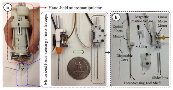
(a) Motorized force-sensing micro-forceps: earlier prototype [17] (left) vs. more compact new prototype (right). (b) Components of the new design: The tip can be easily replaced to accommodate different jaw types for different surgical tasks and prolonged use.
This paper reports the development of an integrated system combining Micron and a new motorized force-sensing micro-forceps. The design and approach can presumably be used in combination with the other active tremor-canceling handheld micromanipulators [15, 16] as well. The target clinical application is membrane peeling in vitreoretinal surgery. The proposed system (1) attenuates hand-tremor when accurate positioning is needed, (2) provides auditory force feedback to the user so that the exerted forces are kept at a safe level, and (3) pulsates the tool tip at high frequency to provide ease in delaminating membranes. In the following sections we will first present the design and calibration of our new tool addressing the previously encountered clinical challenges. This will be followed by system integration steps and the proposed new operation mode. Sections IV and V present experimental performance assessment for membrane peeling on two types of phantoms: a bandage phantom and raw chicken eggs. The paper concludes with a discussion of the results.
II. Hardware Design: Force-Sensing Micro-Forceps
Our micro-forceps consists of two mechanically decoupled pieces: the handle mechanism, and the motorized force-sensing tip.
A. The Handle Mechanism
This part, shown in Fig. 2.a, was designed to clamp around any cylindrical micromanipulator body up to 25 mm in diameter with the help of set screws, transforming it into a micro-forceps handle. It preserves the intuitive actuation mechanism on the existing disposable forceps from Alcon, Inc. (Fort Worth, TX), and does not interfere with the operation of the micromanipulator. The disposable Alcon forceps is one of the most common standard instruments for membrane peeling today and are actuated simply by squeezing the sides of the instrument handle. The squeezing motion causes the tube forming the tool shaft to slide in the distal direction so that the graspers are closed [25]. In our case, however, such rigid coupling between handle motion and tip actuation is not possible since it would significantly interfere with the actuators of the micromanipulator. Instead of such a mechanical coupling, we used a sliding potentiometer on the handle to assess forceps closure. The sides of the handle mechanism are normally kept propped open by two springs. Compressing the sides causes the sliders to move up along the tool handle, inducing a voltage change in the potentiometer output, and driving the motor of the tip forward to close the graspers.
Figure 2.
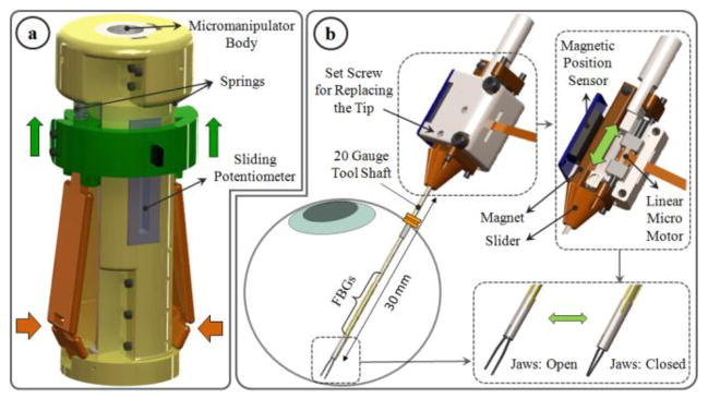
Design of force-sensing micro-forceps for handheld micromanipulators: (a) handle mechanism (b) motorized force-sensing tip with replacable jaws. The tool can be inserted through a 20 Ga trocar into the eye. Squeezing the handle mechanism from the sides drives the motor and pushes the slide assembly forward, and thus closes the grasper jaws.
B. The Motorized Force-Sensing Tip
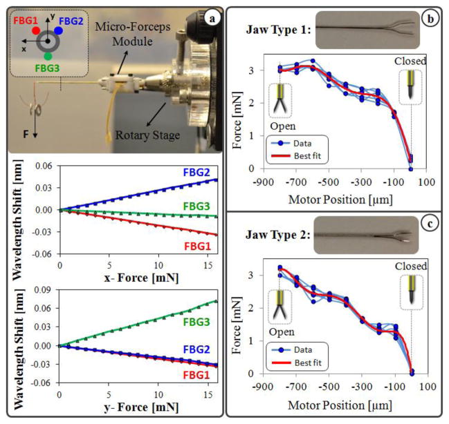
To design a clinically feasible micro-forceps tip that is compatible with various micromanipulators, there are four main challenges that need to be resolved: (1) integrating accurate force sensing capabilities while preserving the grasping motion of the forceps, (2) avoiding interference between the micromanipulator’s own actuation and the opening/closing action of the forceps, (3) generating a self-standing universal module for compatibility with various handheld manipulators, and (4) enabling easy replacement of the grasper jaws for accommodating different jaw types for different surgical tasks, and for disposable use. This requires a very compact and lightweight micro-forceps module that is motorized so that it can be actuated independently regardless of the micromanipulator motion, and that carries all of the force-sensing elements on it. Under these constraints we designed our “drop-in” micro-forceps as shown in Fig. 2.b. using the components in Fig. 1.b.
Reusable forceps require cleaning and sterilization after every operation. As the tool goes through many cycles of operation, the resulting material fatigue and change in surface properties diminish the grasping quality. Consequently, the forceps jaws cannot grasp the membrane as required and in the worst case they may break during the surgery. In addition, depending on the thickness of targeted tissue, surgeons may need to use micro-forceps with varying grasper jaw profiles. For instance, the grasper jaws shown in Fig. 3.b are used for peeling thinner membranes such as internal limiting membranes, whereas the other type in Fig. 3.c is often used for thicker layers such as epiretinal membranes.
Figure 3.
(a) Calibration results: Linear behavior is observed for all FBGs with tip loading in x-axis direction (upper) and in y-axis direction (lower). (b, c) Measured forces vs. the motor position while no external force is applied on the tool tip. Varying nonzero forces are observed due to inner actuation forces as the jaws are opened and closed. The force profile varies depending on the jaw type.
In order to avoid the problems and costs associated with reusable forceps, and to accommodate different jaw types for various clinical tasks, our new micro-forceps module (in contrast to the earlier prototype shown in Fig. 1.a [17]) uses easily replaceable disposable forceps jaws that are at this time taken from the standard 23 Ga Alcon disposable micro-forceps. The normally open jaws are fixed to the base via a set screw located on the lid. The lid, base and slider shown in Fig. 1.b are polycarbonate parts. The tool shaft is a 23 Ga stainless steel tube. It is attached to a slider, which is moved back and forth along the pins of the base by a linear micro motor, Squiggle-RV-1.8 by New Scale Technologies Inc. Driving the slider forward pushes the tool shaft towards the tip, thus squeezing and closing the forceps jaws. The selected micro motor supplies enough force for this task in a very small (2.8×2.8×6 mm), and light weight (0.16 grams) package. Fully opening and closing the jaws requires a travel distance of 0.8 mm, which is well below the motor’s limit (6mm). A bar magnet is attached on the side of the slider. The position of the slider, and thus of the micro motor, is tracked via the magnetic position sensor fixed on the side of the base.
To integrate force sensing capabilities, FBG strain sensors (Smart Fibers, UK) were preferred mainly due to their small dimension, high sensitivity, biocompatibility, sterilizability, and immunity from electrostatic and electromagnetic noise. Following the fabrication method presented in [20], 3 FBGs were fixed evenly around the 23 Ga tubular tool shaft using medical epoxy adhesive. In order to monitor the FBGs, an optical sensing interrogator, sm130–700 from Micron Optics Inc. (Atlanta GA), was used. The outer diameter of the finalized tool shaft is approximately 0.9 mm, and is small enough to fit through a 20 Ga trocar. The module weighs about 1.9 grams.
III. Software Development
A. Calibration and Force Computation
The setup and protocol presented in [20] was followed to calibrate the new micro-forceps module. A linear reproducible behavior was observed for all FBGs as the transverse loading on the tool tip was gradually increased and decreased. The slopes of the response curves presented in Fig. 3.a correspond to the following calibration matrix:
The pseudo-inverse of the calibration matrix (K+) is used in the linear relationship given by (1) to compute the tip forces (F) from FBG wavelength shifts (ΔS).
| (1) |
This algorithm was shown to remove the influence of temperature effectively [20]. Thus, the sensed forces are immune to ambient temperature changes. Furthermore, the shaft of the disposable tip in comparison to the actuation tube is very thin, and thus has no significant affect on the overall stiffness of the tool shaft. Thus even if the tip is replaced, the calibration matrix remains the same.
The grasping action in this design is provided by squeezing the forceps jaws by sliding the tubular tool shaft forward. During this motion, various external loads and friction forces are exerted on this tube, which is also carrying the force-sensing FBGs. As the forceps is closed and opened, FBGs are influenced by these inner actuation forces resulting in a repeated and consistent change in force readings even when there is no external loading on the tip. The force variation due to actuation depends on (1) the type of the attached forceps jaws, and (2) the jaw orientation relative to the base. The sensed actuation forces are usually comparable (up to 3 mN as in Fig. 3.b and 3.c) with the amplitude of most forces during vitreoretinal practice (routinely below 7.5 mN). Due to various structural factors, such as the grasper jaw geometry, friction forces and material properties, the effect of inner actuation forces is usually complex, and thus hard to predict. In order to cancel this systematic error, we implemented a correction routine that needs to be performed after each jaw replacement (Fig. 4).
Figure 4.
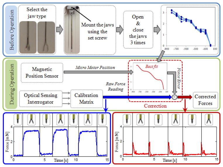
The implemented correction routine for compensating against the inner actuation forces and maintaining the accuracy of force readings while opening and closing the grasper jaws.
Before the operation, the desired jaws are mounted using the set screw on the lid (Fig. 2.b). Then, with no external loading on the tip, the grasper jaws are opened and closed three times while the variation in sensed forces is recorded. This results in a mapping between the micro motor position and force error specific to that particular jaw type and mounting orientation. Then a polynomial is fit to the acquired data. Based on the best fit and sensed motor position, the induced forces due to actuation can be estimated (within a ±0.15 mN envelope) and subtracted from the measured values to obtain a corrected force reading. This provides a significant reduction in force variation as the forceps is closed and opened repeatedly. As shown in Fig. 4, without such correction, opening the forceps jaws induces an error that is slightly larger than 3 mN. The correction routine lowers the error down to 0.3 mN. This indicates that our tool is able to sense transverse forces within an accuracy of 0.3 mN after correction. The jumps on the corrected data correspond to the instant when the actuation tube starts and stops moving, and are mainly due to inertial effects. These jumps can further be reduced by integrating the acceleration term in the correction routine, but has no significance for practical use since the forces while grasping the tissue (while the jaws are stationary) are of interest.
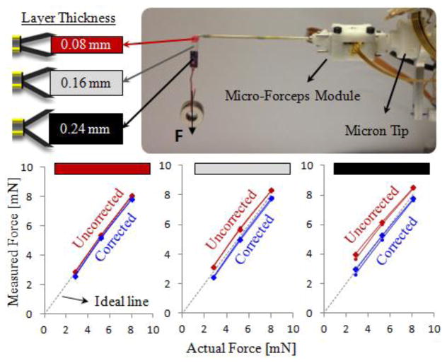
In vitreoretinal practice, surgeons may need to manipulate tissues with varying thickness. Depending on the grasped layer thickness, the jaw opening and the final motor position would change, resulting in different offsets in the raw force reading. The force correction routine based on motor position ensures that the computed tip forces remain accurate regardless of the thickness of the grasped material. In order to validate this, we did experiments for 3 different layer thicknesses, and 3 different tip load levels on the setup shown in Fig. 5. The colored grasping tab carrying the loads is made of bandages and has a non-uniform cross section. The red segment consists of a single layer bandage, while adjacent white and black segments have layers stacked on top of each other, resulting in 0.08mm, 0.16mm and 0.24mm thick material respectively. During the test, the strip was grasped from one of these segments, and washers were hung to increase the forces on the tool tip gradually. The force readings were recorded with and without the proposed correction routine while loading and removing washers. The test was repeated for each segment on the strip. When grasped from the thinnest segment, the measured forces were observed to be very close to the actual values, even without the correction routine. However, as the grasped layer got thicker, the measured values deviated from the ideal line, and thus the correct force value, more if the proposed correction routine was not applied. With the correction routine, the measured forces always remained accurate, regardless of the thickness of the grasped segment.
Figure 5.
The effect of grasped layer thickness on the force sensing accuracy. A multilayered bandage was grasped from 3 different segments to compare the measured forces with the actual loading on the tool tip. Measured forces normally deviate from the ideal line more if thicker layers are grasped. The correction routine ensures that the measured tip forces remain accurate regardless of the thickness of the grasped material.
B. Control Scheme
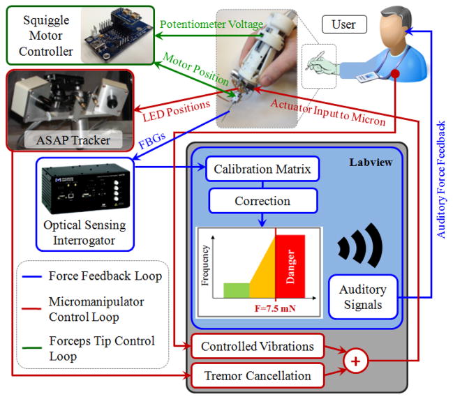
Software implementations were completed using LabVIEW control software. The control scheme of the developed system consists of three independent loops as shown in Fig. 6: Micromanipulator control, forceps tip control, and auditory force feedback loops.
Figure 6.
The control scheme of the integrated system. The existing tremor canceling control loop was extended to inject controlled vibrations for ease in membrane delamination. Opening and closing of the jaws are controlled via the potentiometer on the handpiece. Auditory force feedback is provided to the user to avoid excessive peeling forces.
Micron uses ASAP optical sensors to determine its handle motion [12]. Then this motion is separated into its involuntary and tremulous components. Based on the tremulous components, the required actuator input to Micron’s piezoelectric actuators are determined, and the tip is deflected. This completes the tremor suppression control loop which was previously developed by Riviere et al. In this study, we used Micron and extended its existing LabVIEW control software to include an additional operation mode to assist membrane peeling. This optional mode enables the user to inject controlled high frequency pulses on the tool tip trajectory. The frequency and amplitude of the vibrations are set by the user. When this mode is inactive, the system works in regular tremor cancellation mode, which is good for accurate tool tip motion while approaching the tissue and grasping it. Upon activation of the new mode, Micron not only cancels hand tremor but also starts vibrating the tool tip at the set frequency and amplitude. This feature, by providing an analogous tip motion to the reciprocating needle in biopsy applications [18], may theoretically help break the bonds between the fibrous tissue and the retina surface for easier delamination. The approach is also applicable to other micromanipulators in the field [13–16] with similar tremor suppression (via either optical tracking or inertial sensing) and high frequency pulsation capabilities.
The control loop associated with the actuation of the forceps is shown in green in Fig. 6. Accordingly, analog position servo input is provided by the sliding potentiometer on the handle mechanism to the Squiggle motor controller. The magnetic sensor on the forceps tip provides position feedback to accomplish accurate closed loop control, opening or closing the grasper jaws without noticeable delay.
The auditory force feedback loop is shown in blue. During operation, the wavelength information from each FBG channel is collected and processed at 1 kHz and transmitted over TCP/IP to the LabVIEW environment. Utilizing the calibration matrix, forces are computed. Based on forceps configuration (linear motor position), the computed force value is corrected to obtain tip forces. These tip forces are then converted into auditory signals. The frequency of these audio signals changes with the level of the applied force [21]. Depending on the frequency of the auditory feedback, the user adjusts tool motion so that the applied forces do not exceed 7.5 mN, which we define as the border for the danger zone in membrane peeling based upon our prior in-vivo experience [24].
IV. Experiments
To simulate membrane peeling, tests were done on two types of phantoms, which have previously been used in our laboratory and reported to be suitable surrogates for an epiretinal membrane: bandage phantom, and inner shell membrane (ISM) of raw chicken eggs. Bandage phantom, 2 mm wide strips cut from 19 mm Clear Bandages (RiteAid brand), provides a very consistent platform, and is easy to obtain enabling ample tests. ISM of raw chicken eggs is a biological tissue exhibiting heterogeneous properties, and thus is a more realistic phantom for membrane peeling trials. However, the number of tests that can be done using ISM is limited since a single egg shell is used for each test.
The goal of the experiments was to test the new micro-forceps tip and observe the effect of the new “controlled vibration mode” at various frequencies in comparison to freehand and regular tremor cancellation performances. For this reason, the tests were done in 5 sets:
-
(1)
Freehand peeling;
-
(2)
Micron-assisted peeling with regular tremor cancellation;
-
(3,4,5)
Micron-assisted peeling with tremor cancellation and controlled vibrations at 10 Hz, 30 Hz, and 50 Hz.
In sets 3 to 5, sinusoidal oscillations at the specified frequency were injected to the commanded forceps tip trajectory to oscillate the tool tip back and forth along the peeling direction. The amplitude of vibrations were kept constant at 100μm.
Per set 15 trials on the bandage phantom, 5 trials on ISM were completed. The experiments were performed by a non-surgeon user by alternating the sequence of sets initially on bandage phantom, and then on ISM using the setup shown in Fig. 7. In all cases, the user was provided with auditory force feedback, clearly indicating whether the applied forces are close to or beyond the safety threshold (7.5mN). The challenge was to peel the membranous layer off as quickly as possible while maintaining the peeling force below the threshold, and thus adjusting the peeling speed based on the force feedback. By fixing the exerted forces at their maximum allowable level, the corresponding peeling speed was observed to evaluate the ease of peel in each set.
Figure 7.
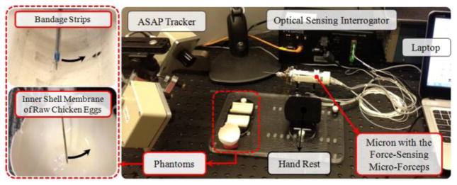
Setup for membrane peeling experiments on bandage phantom and inner shell membrane of raw chicken eggs.
Before data collection, an extensive training period (~1 hr) was allowed for the subject to become accustomed to the system and phantoms, and to minimize learning curve effects in the recorded measurements. During data collection, the tool tip force and position and the Squiggle motor position were recorded. Based upon the Squiggle motor position, the starting and ending points of the delamination were identified in the acquired data. The assessment was based upon the applied forces and tool tip positions during this period. Welch’s power spectral density estimate was used to verify tremor canceling and vibration behavior. The means of peeling force and speed data were compared using one-way ANOVA followed by Tukey’s HSD (honest significant difference) test separately for each phantom type. Statistical significance was defined as p<0.05.
V. Results and Discussion
A. Membrane Peeling on Bandage Phantom
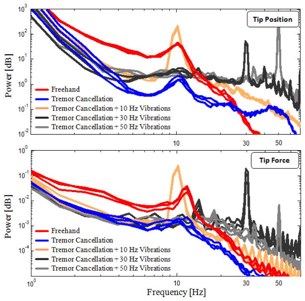
Frequency analyses on tip position and measured peeling forces for 3 sample trials per set are shown in Fig. 8. The frequency of physiological hand tremor in normal humans ranges from 8 to 12 Hz [26]. The prominence of a peak around 10 Hz in the plots of freehand trials is primarily due to subject’s hand tremor. When the tremor cancellation feature of Micron was activated, this peak was largely attenuated and the high frequency components (2–20 Hz) were overall reduced by 80–90% in both position and force spectra. This confirms that the structural modification done for transforming the micromanipulator into a micro-forceps tool, and thus the added inertia at the tip, does not adversely affect the tremor cancelling functionality of Micron. The effect of adding controlled vibrations on tool tip trajectory is clearly visible as peaks at the specified frequencies (10, 30, and 50 Hz), meaning that the low inertia of the designed micro-forceps module allows resonating the tip at high frequencies accurately within Micron’s 1N force capability. The common traits between the tip position and the tip force spectra in all cases indicate a rigid connection between the tool tip and the bandage layer provided by strong grasping of forceps, even when the tip is resonating at 50 Hz.
Figure 8.
Power spectra of tip position and tip forces measured while peeling bandages (3 arbitrary trials per set are shown). Freehand trials exhibit a peak at 10 Hz due to physilogical hand tremor. 80–90% reduction in 2–20 Hz oscillations and visible peaks at 10, 30, and 50 Hz at both spectra reveal success in tremor canceling, strong grasping, and accurate fast tip vibrations.
The mean peeling force and speed for each set is displayed in Table I. Within each set, consistent results were obtained as indicated by the low standard deviation values due to high repeatability of tests on this type of phantom. In all sets, the mean peeling force was maintained just below the set safety threshold (7.5 mN) while trying to maximize the peeling speed as required. The variance analysis showed no significant difference in peeling forces among the sets, meaning that the bandages were peeled off by exerting similar forces (around 7 mN) with the help of the auditory force feedback (p=0.32). However, there was a statistically significant difference among the means of peeling speed (p<0.05). Further analysis with Tukey’s HSD revealed that the mean peeling speed significantly increased as higher frequency oscillations were introduced on the tool tip trajectory during delamination. The mean peeling speed was 0.1392 mm/s in freehand trials whereas upon pulsating the tip at 10, 30 and 50 Hz, it rose respectively to 0.1789, 0.2232 and 0.2809 mm/s. Thus, tremor cancellation combined with 50 Hz vibrations enabled significantly faster peeling as compared to all other sets (p<0.05), and thus provided easier delamination. There was no statistical difference in terms of peeling speed between the freehand trials and the trials with sole tremor cancellation (p=0.21).
TABLE I.
Evaluation Of Cases Based On Average Of All Trials
| Experiments | Number of Trials | Peeling Force [mN] | Peeling Speed [mm/s] | |||
|---|---|---|---|---|---|---|
|
| ||||||
| Mean | Std. Dev. | Mean | Std. Dev. | |||
| Bandages | Freehand | 15 | 6.8584 | 0.3676 | 0.1392 | 0.0216 |
| Tremor Cancellation | 15 | 6.7762 | 0.2894 | 0.1459 | 0.0229 | |
| Tremor Cancellation + 10Hz Vibrations | 15 | 7.0480 | 0.3469 | 0.1789 | 0.0237 | |
| Tremor Cancellation + 30Hz Vibrations | 15 | 6.9440 | 0.3221 | 0.2232 | 0.0472 | |
| Tremor Cancellation + 50Hz Vibrations | 15 | 6.9217 | 0.4403 | 0.2809 | 0.0580 | |
|
| ||||||
| Eggs | Freehand | 5 | 7.7113 | 0.6999 | 0.0868 | 0.0190 |
| Tremor Cancellation | 5 | 7.3107 | 1.2647 | 0.1005 | 0.0288 | |
| Tremor Cancellation + 10Hz Vibrations | 5 | 7.2937 | 0.9752 | 0.1416 | 0.0649 | |
| Tremor Cancellation + 30Hz Vibrations | 5 | 6.9590 | 1.5154 | 0.1850 | 0.0315 | |
| Tremor Cancellation + 50Hz Vibrations | 5 | 6.3405 | 1.3542 | 0.2948 | 0.0609 | |
B. Membrane Peeling on Raw Chicken Eggs
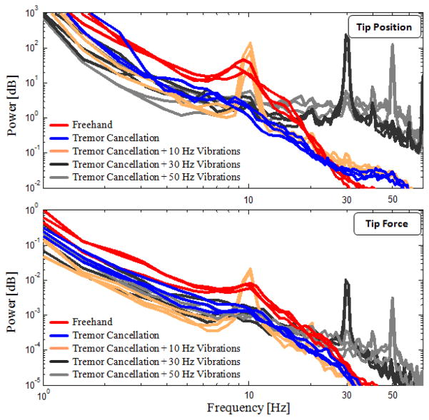
Power density spectra of the trials on chicken eggs is shown for 3 samples per case in Fig. 9. The trend for both the tip position and tip force are similar to those observed on the bandage phantom, though with slightly larger amplitude variation between the sets. The 10 Hz peak due to hand tremor is visible in freehand trials. By tremor cancellation, the oscillations in 2–20 Hz band were reduced by 45–90% and 5–85% respectively in the tip position and tip force spectra.
Figure 9.
Power spectra of tip position and tip forces measured while peeling inner shell membrane of raw chicken eggs (3 arbitrary trials per set are shown). More deviation between trials as compared with bandage phantom, but the main traits were preserved: 45–90% and 5–85% reduction in 2–20 Hz band of tip position and force spectra respectively with tremor cancellation; visible peaks at 10, 30, and 50 Hz at both spectra.
The common properties of the position and force spectra, and the prominence of 10, 30, and 50 Hz peaks in the trials using the new “controlled vibrations mode” strongly indicate that our micro-forceps is able to provide a rigid connection between the tool and the membrane being peeled also on this biological tissue, even when resonating the tip at high frequencies. Previously, when using a pick instrument instead of a micro-forceps [27], the slippage between the tool and the tissue was causing problems in manipulation of ISM, and such correlation between the tool tip dynamics and tool-to-tissue forces was not possible.
Peeling ISM of chicken eggs requires slightly larger forces than those for the bandage phantom. These forces are in fact a combination of tearing and delaminating forces in contrast to sole delaminating forces involved in bandage peeling. As shown in Table I, in freehand trials, the recorded peeling forces averaged approximately 7.7 mN, which is slightly above the set threshold (7.5 mN). The corresponding mean peeling speed though is very slow (0.0868 mm/s). In these freehand trials, the user tried to stay below 7.5 mN threshold by peeling the membrane as slow as he could. This was however limited by the unintentional tool motion due to hand tremor. In addition, being a biological tissue, ISM exhibits slight variations in tissue properties within the same layer as well as between the eggs. Using ISM, it is harder to adjust peeling forces, since the exerted forces are not only related to tool tip speed, but also depend on local tissue properties. This behavior more closely simulates the real vitreoretinal practice. Due to these variations, the standard deviations in all sets were higher than those for the bandages.
The ANOVA analysis revealed that the difference in the mean peeling force among groups is not statistically significant (p=0.47). However, similar to the results for bandages, the tested cases significantly differ in terms of average peeling speed (p<0.05). Based on Tukey’s HSD, controlled micro-vibrations of the tool tip provided ease in peeling, enabling faster delamination at the same force level. The mean peeling speed was 0.0868 mm/s in freehand trials whereas upon pulsating the tip at 10, 30, and 50 Hz, it rose respectively to 0.1416, 0.1850, and 0.2948 mm/s. The difference between freehand trials and trials with sole tremor cancellation was not statistically significant (p=0.20).
VI. Conclusion
In this study, an integrated assistive system for membrane peeling in vitreoretinal surgery has been proposed. First, a compact, lightweight, force-sensing micro-forceps module was developed and integrated with a micro-manipulator, Micron. Second, the existing tremor cancellation software of Micron was extended to inject micro-vibrations on the tool tip trajectory when necessary to assist membrane delamination. Finally, the resulting system was tested in peeling trials using bandages and raw chicken eggs.
The designed micro-forceps module enables easy replacement of the disposable grasper jaws for better surgical performance in prolonged use, and for accommodating various jaw profiles for wider range of applications. FBGs located on the tool shaft sense the forces at the tool tip with a resolution of 0.3 mN. The mechanically decoupled design of the tip module from the handle mechanism, and its low inertia (1.9 g) ensure no adverse effect upon Micron’s tremor canceling performance, and make high frequency micro-vibrations possible within the force limits of Micron. This design also provides flexibility in implementation: both the tip module and handle mechanism are not specific to Micron, and can presumably be integrated with other handheld micromanipulators easily.
Experiments on bandages and raw chicken eggs have revealed that controlled micro-vibrations provide ease in delaminating membranes. Applying similar amount of forces, much faster delamination was observed when the frequency of these vibrations were increased (up to 50 Hz) while keeping the amplitude fixed (at 100 μm). The mechanics behind this behavior as well as the effect of micro-vibration amplitude for both types of phantoms are yet to be explored. In addition, the experiments in this study were done open-sky following a linear peeling trajectory. The effect of introducing a sclerotomy constraint needs to be explored before this method can be proposed as a clinically feasible assistance option. It is not yet known what the effect of micro-vibrations are on underlying retinal tissues. Upon completion of these steps, we aim to extend our results through multiple subject experiments and to begin to explore feasibility in animal models.
Acknowledgments
The authors thank Prof. Cameron Riviere and his team at Carnegie Mellon University for providing the Micron robot, and Alcon, Inc. (Fort Worth, TX) for their help with providing the disposable micro-forceps tools.
Footnotes
Research supported in part by the National Institutes of Health under R01 EB007969, and R01 EB000526, and in part by Johns Hopkins University internal funds.
Contributor Information
Berk Gonenc, Email: bgonenc1@jhu.edu, CISST ERC at Johns Hopkins University, Baltimore, MD 21218 USA.
Peter Gehlbach, Email: pgelbach@jhmi.edu, Wilmer Eye Institute at The Johns Hopkins School of Medicine, Baltimore, MD 21287 USA.
James Handa, Email: jthanda@jhmi.edu, Wilmer Eye Institute at The Johns Hopkins School of Medicine, Baltimore, MD 21287 USA.
Russell H. Taylor, Email: rht@jhu.edu, CISST ERC at Johns Hopkins University, Baltimore, MD 21218 USA.
Iulian Iordachita, Email: iordachita@jhu.edu, CISST ERC at Johns Hopkins University, Baltimore, MD 21218 USA.
References
- 1.Gupta P, Jensen P, de Juan E. Surgical forces and tactile perception during retinal microsurgery. Proc. MICCAI’99; 1999; pp. 1218–1225. [Google Scholar]
- 2.Tsilimbaris MK, Lit ES, D’Amico DJ. Retinal microvascular surgery: A feasibility study. Invest Ophthalmol Vis Sci. 2004 Jun;45(6):1963–1968. doi: 10.1167/iovs.03-0874. [DOI] [PubMed] [Google Scholar]
- 3.Sjaarda RN, Glaser BM, Thompson JT, Murphy RP, Hanham A. Distribution of iatrogenic retinal breaks in macular hole surgery. Ophthalmology. 1995 Sep;102(9):1387–1392. doi: 10.1016/s0161-6420(95)30859-7. [DOI] [PubMed] [Google Scholar]
- 4.Nakata K, Ohji M, Ikuno Y, Kusaka S, Gomi F, Tano Y. Sub-retinal hemorrhage during internal limiting membrane peeling for a macular hole. Graefes Arch Clin Exp Ophthalmol. 2003 Jul;241:582–584. doi: 10.1007/s00417-003-0676-y. [DOI] [PubMed] [Google Scholar]
- 5.Schenker PS, Barlow EC, Boswell CD, Das H, Lee S, Ohm TR, Paljug ED, Rodriguez G, Charles ST. Development of a telemanipulator for dexterity enhanced microsurgery. Proc. 2nd Int Symp Med Rob Comput Asst Surg; 1995; pp. 81–88. [Google Scholar]
- 6.Hunter IW, Jones LA, Sagar MA, Lafontaine SR, Hunter PJ. Opthalmic microsurgical robot and associated virtual environment. Comput Biol Med. 1995 Mar;25:2:173–182. doi: 10.1016/0010-4825(94)00042-o. [DOI] [PubMed] [Google Scholar]
- 7.Ueta T, Yamaguchi Y, Shirakawa Y, Nakano T, Ideta R, Noda Y, Morita A, Mochizuki R, Sugita N, Mituishi M, Tamaki Y. Robot-assisted vitreoretinal surgery: Development of a prototype and feasibility studies in an animal model. Ophthalmology. 2009 Aug;116(8):1538–1543. doi: 10.1016/j.ophtha.2009.03.001. [DOI] [PubMed] [Google Scholar]
- 8.Das H, Zak H, Johnson J, Crouch J, Frambach D. Evaluation of a telerobotic system to assist surgeons in microsurgery. Comput Aided Surg. 1999;4(1):15–25. doi: 10.1002/(SICI)1097-0150(1999)4:1<15::AID-IGS2>3.0.CO;2-0. [DOI] [PubMed] [Google Scholar]
- 9.Jensen PS, Grace KW, Attariwala R, Colgate JE, Glucksberg MR. Toward robot-assisted vascular microsurgery in the retina. Graefes Arch Clin Exp Ophthalmol. 1997 Nov;235(11):696–701. doi: 10.1007/BF01880668. [DOI] [PubMed] [Google Scholar]
- 10.Mulgaonkar AP, Hubschman JP, Bourges JL, Jordan BL, Cham C, Wilson JT, Tsao TC, Culjat MO. A prototype surgical manipulator for robotic intraocular micro surgery. Stud Health Technol Inform. 2009;142:215–217. [PubMed] [Google Scholar]
- 11.Uneri A, Balicki MA, Handa J, Gehlbach P, Taylor RH, Iordachita I. New steady-hand Eye Robot with micro-force sensing for vitreoretinal surgery. Proc. 3rd IEEE RAS EMBS Int Conf Biomed Robot Biomechatron (BioRob); 2010; pp. 814–819. [DOI] [PMC free article] [PubMed] [Google Scholar]
- 12.MacLachlan RA, Becker BC, Cuevas Tabarés J, Podnar GW, Lobes LA, Riviere CN. Micron: an actively stabilized handheld tool for microsurgery. IEEE Trans Robot. 2012 Feb;28(1):195–212. doi: 10.1109/TRO.2011.2169634. [DOI] [PMC free article] [PubMed] [Google Scholar]
- 13.Latt WT, Tan UX, Shee CY, Ang WT. A compact handheld active physiological tremor compensation instrument. Proc. IEEE/Amer. Soc. Mech. Eng. Int. Conf. Adv. Intell. Mechatronics; 2009; pp. 711–716. [Google Scholar]
- 14.Payne CJ, Kwok K, Yang G. An ungrounded hand-held surgical device incorporating active constraints with force-feedback. Proc. IEEE Int. Conf. on Intelligent Robots and Systems (IROS ’13); 2013; pp. 2559–2565. [DOI] [PMC free article] [PubMed] [Google Scholar]
- 15.Chang D, Gu GM, Kim J. Design of a novel tremor suppression device using a linear delta manipulator for micromanipulation. Proc. IEEE Int. Conf. on Intelligent Robots and Systems (IROS ’13); 2013; pp. 413–418. [Google Scholar]
- 16.Saxena A, Patel RV. An active handheld device for compensation of physiological tremor using an ionic polymer metallic composite actuator. Proc. IEEE Int. Conf. on Intelligent Robots and Systems (IROS ’13); 2013; pp. 4275–4280. [Google Scholar]
- 17.Gonenc B, Feldman E, Gehlbach P, Handa J, Taylor RH, Iordachita I. Towards Robot-Assisted Vitreoretinal Surgery: Force-Sensing Micro-Forceps Integrated with a Handheld Micromanipulator. IEEE Int. Conf. on Robotics and Automation (ICRA ’14); 2014; accepted. [DOI] [PMC free article] [PubMed] [Google Scholar]
- 18.Damadian J. Method of conducting a needle biopsy procedure. 6 702 761. US Patent. 2001 Mar 6;
- 19.Sun Z, Balicki M, Kang J, Handa J, Taylor R, Iordachita I. Development and preliminary data of novel integrated optical micro-force sensing tools for retinal microsurgery. Proc. IEEE Int. Conf. on Robotics and Automation (ICRA ’09); 2009; pp. 1897–1902. [Google Scholar]
- 20.Iordachita I, Sun Z, Balicki M, Kang J, Phee S, Handa J, Gehlbach P, Taylor R. A sub-millimetric, 0.25 mn resolution fully integrated fiber-optic force-sensing tool for retinal microsurgery. International Journal of Computer Assisted Radiology and Surgery. 2009 Jun;4:383–390. doi: 10.1007/s11548-009-0301-6. [DOI] [PMC free article] [PubMed] [Google Scholar]
- 21.Balicki M, Uneri A, Iordachita I, Handa J, Gehlbach P, Taylor R. Micro-force Sensing in Robot Assisted Membrane Peeling for Vitreoretinal Surgery. Med Image Comput Comput Assist Interv.; 2010; pp. 303–310. [DOI] [PMC free article] [PubMed] [Google Scholar]
- 22.Gonenc B, Balicki MA, Handa J, Gehlbach P, Riviere CN, Taylor RH, Iordachita I. Preliminary Evaluation of a Micro-Force Sensing Handheld Robot for Vitreoretinal Surgery. Proc. IEEE Int. Conf. on Intelligent Robots and Systems (IROS ’12); 2012; pp. 4125–4130. [DOI] [PMC free article] [PubMed] [Google Scholar]
- 23.Charles S. Techniques and tools for dissection of epiretinal membranes. Graefe’s Archive for Clinical and Experimental Ophthalmology. 2003 May;241:5:347–352. doi: 10.1007/s00417-003-0624-x. [DOI] [PubMed] [Google Scholar]
- 24.He X, Balicki MA, Kang JU, Gehlbach PL, Handa JT, Taylor RH, Iordachita II. Force sensing micro-forceps with integrated fiber bragg grating for vitreoretinal surgery. Proc of SPIE. 2012 Feb;8218:82180W1–7. [Google Scholar]
- 25.Kuru I, Gonenc B, Balicki M, Handa J, Gehlbach P, Taylor RH, Iordachita I. Force Sensing Micro-Forceps for Robot Assisted Retinal Surgery. Proc. International Conference of the IEEE EMBS (EMBC ’12); 2012. pp. 1401–1404. [DOI] [PMC free article] [PubMed] [Google Scholar]
- 26.Elble RJ, Randall JE. Mechanistic Components of Normal Hand Tremor. Electroencephalography and Clinical Neurophysiology. 1978 Jan;44(1):72–82. doi: 10.1016/0013-4694(78)90106-2. [DOI] [PubMed] [Google Scholar]
- 27.Gonenc B, Handa J, Gehlbach P, Taylor RH, Iordachita I. A Comparative Study for Robot Assisted Vitreoretinal Surgery: Micron vs. the Steady-Hand Robot. Proc. IEEE Int. Conf. on Robotics and Automation (ICRA ’13); 2013; pp. 4832–4837. [DOI] [PMC free article] [PubMed] [Google Scholar]


