

Abstract
Background
Deep brain stimulation (DBS) treats the symptoms of several movement disorders, but optimal selection of stimulation parameters remains a challenge. The evoked compound action potential (ECAP) reflects synchronized neural activation near the DBS lead, and may be useful for feedback control and automatic adjustment of stimulation parameters in closed-loop DBS systems.
Objectives
Determine the feasibility of recording ECAPs in the clinical setting, understand the neural origin of the ECAP and sources of any stimulus artifact, and correlate ECAP characteristics with motor symptoms.
Methods
The ECAP and tremor response were measured simultaneously during intraoperative studies of thalamic DBS, conducted in patients who were either undergoing surgery for initial lead implantation or replacement of their internal pulse generator.
Results
There was large subject-to-subject variation in stimulus artifact amplitude, which model-based analysis suggested may have been caused by glial encapsulation of the lead, resulting in imbalances in the tissue impedance between the contacts. ECAP recordings obtained from both acute and chronically implanted electrodes revealed that specific phase characteristics of the signal varied systematically with stimulation parameters. Further, a trend was observed in some patients between the energy of the initial negative and positive ECAP phases, as well as secondary phases, and changes in tremor from baseline. A computational model of thalamic DBS indicated that direct cerebellothalamic fiber activation dominated the clinically measured ECAP, suggesting that excitation of these fibers is critical in DBS therapy.
Conclusions
This work demonstrated that ECAPs can be recorded in the clinical setting and may provide a surrogate feedback control signal for automatic adjustment of stimulation parameters to reduce tremor amplitude.
Keywords: evoked compound action potential, neural recording, computer simulation, stimulus artifact, movement disorders
Introduction
Deep brain stimulation (DBS) is an effective therapy for movement disorders, including essential tremor (ET) (1, 2). To treat ET and some patients with tremor-dominant Parkinson’s disease (PD), the DBS lead is typically implanted in the ventral intermediate (Vim) nucleus of the thalamus, and is connected to an internal pulse generator (IPG) via a subcutaneous wire. The subsequent selection of stimulation parameters is an ad hoc, empirical process. Parameter adjustment sessions are inconvenient, time-consuming, and costly (3), and due to a lack of standardized programming approaches, parameters can often be improved (4). Moreover, inappropriate parameter settings can lead to side effects (5) and deplete the battery more quickly than optimized settings (6). An automated selection of DBS parameters could reduce follow-up visits and improve patient outcomes, using either external tremor measurements or internal neurological activity as a rapid feedback signal.
Implementing closed-loop DBS systems may provide an approach to automated selection and optimization of stimulation parameters. Neural activity measured during DBS may provide information related to symptoms, and both single-unit recordings and local field potentials (LFPs) have been proposed as potential feedback signals. Closed-loop DBS of the globus pallidus interna (GPi), triggered from single-unit activity measured from the primary motor cortex (M1), generated greater motor symptom reduction in MPTP-treated monkeys than continuous, open loop stimulation (7). However, this approach required implantation of additional hardware, and the long-term stability of microelectrode recordings may not be sufficient for clinical use (8). Alternatively, LFPs can be recorded from the DBS lead, and reflect synchronized oscillatory neural activity across wide networks (9). Theta oscillations recorded from the thalamus may be related to tremor in ET and PD (10, 11). Proposed LFP-based closed-loop systems would titrate stimulation in response to changes in ongoing LFP activity (12), or select the most effective stimulation contacts and inform DBS voltage settings, as demonstrated for DBS treatment of PD (13–15). However, further work is required to demonstrate that LFPs are sufficiently correlated with clinical symptoms to provide a surrogate closed-loop measure.
In the present work we investigated the evoked compound action potential (ECAP) as a potential feedback control signal for thalamic DBS. The ECAP is generated by synchronous activation of an ensemble of neural elements near the lead, and can be recorded from two non-stimulating contacts on the DBS lead implanted for therapy (16). An ECAP-based closed loop DBS system could potentially adjust stimulation settings automatically to generate activation of the appropriate neural elements. An analogous ECAP-based approach has successfully guided stimulation levels in cochlear implants (17, 18) and spinal cord stimulation systems (19). We showed previously the feasibility of recording ECAPs using a novel stimulus artifact suppression system in acute, preclinical experiments (16), and demonstrated the insight provided by ECAPs into the extent and types of neural elements activated during thalamic DBS (20). The objectives of the present work were to determine: 1) whether ECAPs could be recorded during clinical DBS, 2) the source of the ECAP and any artifact, 3) changes in ECAP characteristics across DBS parameters, and 4) correlation of ECAP characteristics with changes in tremor across DBS parameters.
Methods and Materials
We conducted intraoperative recordings of ECAPs under acute and chronic lead implantation conditions and investigated correlations between ECAP characteristics and tremor across stimulation parameters. Computational modeling was used to investigate the origin of the ECAP signal and stimulus artifact.
Human subjects
The protocol was reviewed and approved by the Institutional Review Boards at Duke University and Emory University, and subjects participated on a volunteer basis after providing written informed consent. The study enrolled 19 participants, 15 with ET, 3 with tremor-dominant PD, and 1 with Fragile X-associated tremor/ataxia syndrome (FXTAS) (21). Two of the enrolled subjects did not complete the study. We recruited patients who were either undergoing surgical implantation of the Medtronic 3389 DBS lead in Vim (acute setting, n=8) or replacement of their battery-depleted IPG and were at least three-months post-implant of a Medtronic 3387 or 3389 DBS lead in Vim (chronic setting, n=11), as detailed in Table 1. Additional subject inclusion criteria included neurologically stable patients who could understand the study and consent form; exclusion criteria were an inability to execute motor tasks during the study, and clinically ineffective DBS for those persons receiving a replacement IPG. Subjects undergoing IPG replacement surgery were given monitored anesthesia care together with local anesthetic (1% lidocaine), such that they were responsive during the study, and were asked to decline sedation, which can otherwise reduce motor symptoms. Subjects undergoing initial DBS implantation are normally given local anesthesia, and sedation was provided only as necessary so as to minimize the effect on motor symptoms. If sedation was given, it was discontinued prior to data collection, such that the patient was no longer drowsy. All subjects were asked to withhold anti-tremor and/or dopaminergic medications overnight prior to the study, and subjects that were unable to tolerate withholding medications were excluded from the study. Demographic information and relevant medication and anesthesia details for the subjects are provided in Table 1.
Table 1.
Subject demographic characteristics, lead information, and relevant medications taken or anesthesia delivered on the morning of the study. The time between delivery of medications or anesthesia and the start of the study are provided in parentheses. Asterisk (*) indicates that the subject underwent DBS lead implantation surgery.
| Subject | Age/Gender | Diagnosis | Medtronic Electrode | Mo. After Implant | Medications Taken Morning of Study (Approx. Delay from Delivery to Study Start Time) |
|---|---|---|---|---|---|
| EP12A | 65/M | ET | 3389 | 34 | None |
| EP12B | 73/M | ET | 3387 | 44 | None |
| EP12C | 68/M | PD | 3387 | 58 | None |
| EP12D | 73/F | ET | 3387 | 77 | None |
| EP12E | 76/M | PD | 3387 | 40 | None |
| EP13A | 72/M | ET | 3387 | 74 | Gabapentin, divalproex before surgery; fentanyl before/during surgery (>15 min) |
| EP13B* | 74/F | ET | 3389 | 0 | Primidone before surgery; fentanyl (80 min), midazolam (>50 min), dexmedetomidine (70 min) during surgery |
| EP13C* | 73/F | ET with mild Parkinsonism | 3389 | 0 | Primidone before surgery |
| EP13E* | 64/M | FXTAS | 3389 | 0 | Fentanyl during surgery (>15 min) |
| EP13F | 74/M | PD | 3387 | 90 | Isoflurane, dexmedetomidine during surgery (30 min) |
| EP13G* | 62/M | ET | 3389 | 0 | Propofol during surgery (45 min) |
| EP13H* | 66/M | ET | 3389 | 0 | Propofol during surgery (>40 min) |
| EP13I* | 70/F | ET | 3389 | 0 | Propofol (>30 min), fentanyl (>105 min) during surgery |
| EP13J* | 61/F | ET | 3389 | 0 | Fentanyl before surgery; midazolam (65 min), propofol (70 min) during surgery |
| EP13K | 71/M | ET | 3387 | 176 | Gabapentin before surgery |
| EP13L | 69/M | ET | 3389 | 74 | None |
| EP13N* | 69/F | ET | 3389 | 0 | Propofol during surgery (>50 min) |
One adverse event unrelated to the study occurred: a postoperative reaction to antibiotics directly administered at the IPG site, which resolved uneventfully. Some patients also reported transient paresthesias during stimulation delivered during the study.
Intraoperative experimental setup
After implantation of the DBS lead or removal of the battery-depleted IPG, the DBS brain lead or extension cable, respectively, was externalized and connected to hardware for stimulation and recording via a temporary, sterile cable (22). For subjects undergoing initial lead implantation, the connection to the DBS lead was made through a Twistlock Screening Cable (3550-03, Medtronic). In subjects undergoing IPG replacement, the connection to the DBS extension cable was made through a Multi-Lead Trialing Cable (355531, Medtronic) and a 1×4 Pocket Adaptor (64001, Medtronic) (22).
ECAPs were recorded differentially between two non-stimulating contacts using three series AC-coupled amplifier stages (A1, A2, and A3) and additional circuit components to reduce the stimulus artifact (Fig. S1A) (16). The more ventral and dorsal contacts provided the positive and negative inputs, respectively, to the differential amplifier. The gains at each amplifier stage were set to ensure that amplifier saturation did not occur, and the signal was band-pass filtered at A2 and A3 using a low-pass cutoff of 10 kHz and a high-pass cutoff of 0.1 Hz (or 10 Hz, EP12A–D only). Further, the second and third amplifier stages were blanked for the duration of the stimulus pulse and the subsequent 60 μs. DBS was delivered through an isolated stimulator (bp isolator, FHC) connected in series with two 100 μF capacitors, with stimulation pulses controlled via a high-speed digital-to-analog converter using a custom LabView program (National Instruments), which also controlled digital pulses to operate circuit components (16) and sampled the ECAP at 80 kHz.
Stimulation was applied unilaterally with symmetric, biphasic, voltage-regulated pulses. Charge densities were below the manufacturer’s recommended limit of 30 μC/cm2, using a conservative impedance estimate of 500 Ω (6). We used a monopolar stimulation configuration with symmetrical recording contacts to minimize the size of the artifact (16). In choosing the hemisphere for stimulation in subjects that had or were receiving bilateral lead implants, we decided laterality based on dominance, side with greater tremor symptoms with DBS off, and side with lower clinical amplitude and pulse width (IPG replacement subjects only). Further, we preferred the side that used a clinical stimulation configuration with contacts 1 or 2 (where contacts are labeled 0–1–2–3 in the ventral-to-dorsal direction), as it was necessary to use one of these contacts in the monopolar stimulation – symmetrical recording configuration, and we sought to match the clinical configuration as closely as possible (Table 2). For subjects undergoing lead implantation, clinical settings were determined by a neurologist during surgery as the parameters and contacts that maximized tremor reduction without side effects. The recording reference electrode (RedDot M2255, 3M) was placed on the skin, either on the chest opposite the surgical site (EP12A only) or the thigh ipsilateral to stimulation (Fig. S1B). For subjects undergoing IPG replacement, the stimulation counter electrode (StimCare Carbon Foam Electrode, Empi) was placed on the thigh (EP12A only) or the chest opposite the surgical site, and in subjects undergoing lead implantation, the retractor at the cranial burr hole or implant cannula (EP13I and EP13J) was used as the counter electrode.
Table 2.
Clinical stimulation settings and study settings for each subject. For stimulation contacts, “C” corresponds to case return for the clinical settings, and a distant counter electrode for study settings. Degree symbol (°) indicates that the subject performed a counting task during tremor measurement.
| Subject | Clinical Settings | Study Settings | |||||
|---|---|---|---|---|---|---|---|
|
| |||||||
| Voltage (V) | Frequency (Hz) | Pulse Width (μs) | Stim. Contacts | Stim. Contacts | Rec. Contacts | Arm Position During Tremor Measurement | |
| EP12A° | 6.1 | 185 | 60 | 0−/1−/C+ | 1−/C+ | 0+/2− | Elbow flexed and unsupported, hand held near face, holding tape roll |
| EP12B° | 4.1 | 145 | 90 | 1−/C+ | 1−/C+ | 0+/2− | Elbow extended and unsupported, arm ~30 deg above horizontal |
| EP12C | 4.6 | 150 | 60 | 0−/1+ | 1−/C+ | 0+/2− | Elbow flexed 90 deg and unsupported |
| EP12D° | 1.8 | 180 | 90 | 0−/C+ | 1−/C+ | 0+/2− | Elbow flexed and unsupported, hand held near face |
| EP12E | 4.6 | 185 | 90 | 1−/2−/C+ | 2−/C+ | 1+/3− | Elbow extended and supported, arm parallel to horizontal |
| EP13A° | 2.3 | 180 | 60 | 1−/2−/3+ | 1−/C+ | 0+/2− | Elbow extended and unsupported, arm parallel to horizontal |
| EP13B° | 1 | 180 | 90 | 1−/0+ | 1−/C+ | 0+/2− | Elbow extended and unsupported, arm ~30 deg above horizontal |
| EP13C | 1 | 180 | 90 | 1−/0+ | 1−/C+ | 0+/2− | Elbow flexed and supported, arm ~30 deg above horizontal |
| EP13E | 1 | 180 | 90 | 0−/1+ | 1−/C+ | 0+/2− | Elbow extended and unsupported, arm ~45 deg above horizontal |
| EP13F° | 4.6 | 90 | 60 | 0−/1−/3+ | 1−/C+ | 0+/2− | Elbow flexed and unsupported, arm perpendicular to horizontal |
| EP13G | 2 | 180 | 90 | 1−/0+ | 1−/C+ | 0+/2− | Elbow flexed and unsupported, hand held near face |
| EP13H | 1 | 180 | 60 | 2−/3+ | 1−/C+ | 0+/2− | Elbow flexed and unsupported, hand held near face, holding water bottle |
| EP13I° | 1 | 180 | 90 | 1−/2+ | 1−/C+ | 0+/2− | Elbow flexed and unsupported, hand held near face, holding cup |
| EP13J | 2 | 185 | 90 | 1−/2+ | 1−/C+ | 0+/2− | Elbow extended and unsupported, arm parallel to horizontal |
| EP13K | 4.4 | 185 | 90 | 1+/2−/3− | 2−/C+ | 1+/3− | Elbow extended and unsupported, arm parallel to horizontal |
| EP13L° | 1.6 | 150 | 60 | 1−/0+/2+ | 1−/C+ | 0+/2− | Elbow flexed 90 deg and unsupported, arm perpendicular to horizontal, holding cup/tape |
| EP13N | 2 | 185 | 90 | 1−/2+ | 1−/C+ | 0+/2− | Elbow flexed 90 deg and unsupported, arm perpendicular to horizontal |
We measured tremor with an accelerometer (5 V/4 g sensitivity, CXL04LP3, Crossbow Technology, sampled at 1 kHz) taped to the dorsum of the hand contralateral to stimulation. Tremor was measured by having the supine subject hold their arm in a position that was predetermined to produce tremor, and with the wrist extended such that it was parallel with the forearm (Table 2).
Stimulation and measurement protocol
We measured ECAPs and tremor in single study sessions lasting approximately 45 min or until the patient was fatigued. In the first phase of the study, we determined the maximum tolerable voltage by slowly increasing the amplitude up to 140% of the clinical voltage (VCLIN) of DBS delivered for 5 s at 130 Hz with the clinical pulse width and cathodic-phase first polarity. In the second phase, we measured ECAPs and tremor across a range of stimulation parameters delivered in a randomized manner with both the subject and the experimenter who was interacting with the subject blinded. Frequency was 10 Hz or 130 Hz, and we typically tested only VCLIN for the former and a range of amplitudes for the latter. However, if the subject had low tremor power in the DBS off condition, a range of amplitudes was instead tested at 10 Hz. Due to the expected tremor exacerbation at 10 Hz, this was an attempt to generate differential tremor measurements, compared to baseline, across a larger number of trials. Amplitudes were 20%, 60%, 100%, and 140% of VCLIN, but if a higher voltage was not tolerated in the first study phase, then we used lower proportions of VCLIN. Additionally, we tested both cathodic- and anodic-phase first polarities, and pulse width was fixed at the clinical setting.
Each trial within the block was 2 min in duration, with DBS off for the first minute (baseline period) and DBS on for the second minute (stim period) (Fig. 1A). At approximately 30 s into the baseline and stim periods, we measured the subjects’ tremor for 20 s. We recorded ECAPs in the stim period, either just when tremor was measured (EP12A–C only) or through the entire period. Depending on patient fatigue, we conducted a second block with different randomized presentation of stimulation parameters in some studies. We were unable to complete the first block of the second phase in subjects EP13B, EP13C, EP13H, and EP13J due to subject fatigue. A poor connection between the hardware and DBS lead or between the reference electrode and skin in EP13C, EP13E, and EP13H led to low ECAP signal fidelity, and no further analysis was conducted for these studies.
Figure 1.
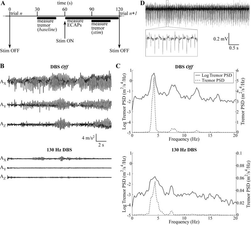
Intraoperative measurements of ECAPs and tremor. (A) The timeline of each trial, in which ECAPs were measured during DBS (stim) and tremor was recorded during baseline and stim periods. (B) Raw accelerometer measurements made for 20 s along the X-, Y-, and Z-axes for EP12E during 130 Hz DBS at the clinical voltage (VCLIN) with cathodic-phase first polarity, and in the preceding baseline period with DBS off. (C) Power spectral density (PSD) of the tremor data from (B) on both a log scale, for comparison between DBS off and DBS on conditions, and a linear scale, for comparison of the relative magnitude of different peaks in the signals. (D) Raw ECAP recording made from EP12D for 130 Hz DBS at VCLIN with cathodic-phase first polarity.
Postoperative measurement of impedance
Following completion of the study, an IPG (Activa, Medtronic) was implanted (except in some patients undergoing initial DBS lead implantation surgery), and post-operative electrode impedance measurements were taken with the Activa device. The Activa impedance measurement used trains of 0.7 or 1.5 V, 80 μs/phase, and 100 Hz, applied between pairs of contacts or between one contact and the IPG case. Impedance was measured at the beginning of the pulse, and since the double-layer capacitance of the electrode-tissue interface (ETI) is shorted at high frequencies (23), the impedance measurement was dominated by the tissue resistance.
Data analysis
Tremor was analyzed by calculating the power spectral density (PSD) of the acceleration measured along each axis (AX, AY, and AZ). The acceleration signals were detrended using local linear regression (2 s window size, 1 s step size) (Fig. 1B), the PSD was calculated in MATLAB using the psd function (Welch’s averaged periodogram, Hanning window, fast Fourier transform (FFT) length of 5,000 samples) with corrected amplitude scaling (Fig. 1C), and tremor power was calculated in the X-, Y-, and Z-dimensions by integrating each spectrum over the 2–7 Hz band, to get PX, PY, and PZ (24). This band was chosen to include the fundamental frequency and first harmonic (Fig. 1C). Finally, we summed PX, PY, and PZ, and change in tremor was quantified for each of n trials as:
where Pn,stim was tremor power measured during the stim period of trial n and Pn,baseline was that measured during the baseline period of trial n.
The ECAP was analyzed by calculating signal power in different ECAP phases (20). First, the raw ECAP signal (Fig. 1D) was averaged using stimulus-triggering across the first 64 responses for an 8× increase in signal-to-noise. Second, in studies with a large stimulus artifact tail, we used a polarity averaging technique common in cochlear ECAP recording (25), in which responses recorded with opposite polarities (but other stimulation parameters identical) were averaged together. The artifact was expected to be inverted for opposite stimulation polarities and was removed with this technique, whereas the ECAP response was expected to be similar for opposite polarities with symmetric, biphasic DBS pulses and so was relatively unaffected by polarity averaging (20). Third, any signal offset was calculated as the average of the final 1 ms of signal and subtracted. Finally, we squared the signal and integrated across distinct ECAP phases. The resulting signal energy measure accounted for both the magnitude and duration of the phases.
Pearson correlation coefficients were calculated for linear regressions between tremor and ECAP signal energy values. One-tailed t-tests were performed to determine whether the slope of the regression was significantly different from zero (α=0.05), with an expected negative slope at 130 Hz DBS and positive slope at 10 Hz DBS.
Computational model of ECAP recording during thalamic DBS
A computational model of thalamic DBS was used to calculate the ECAP and corresponding neural element activation, and thereby investigate the origin of the recorded signal. This three stage model was discussed in detail in (20), and is reviewed briefly here.
The first stage of the model used the finite element method (FEM) in COMSOL v3.4 to calculate the potentials generated by a three-dimensional representation of the DBS lead within brain tissue (Fig. S2A). A clinical DBS lead (Medtronic model 3387 or 3389) was placed within a prism representation of the Vim thalamus (26), all encompassed within a cylindrical representation of surrounding brain tissue with height and diameter of 190.5 mm. The conductivity of brain tissue was (27), and that of the DBS contact and insulation were 5×10⁶ S/m and 1×10⁻¹³ S/m, respectively (28). Sensitivity analysis of the FEM model volume and mesh size was conducted previously (29).
In the second stage, multi-compartment cable NEURON models with appropriate geometrical and ion channel representations of the dendrites, soma, and axon of 500 thalamocortical (TC) neurons were randomly distributed in the thalamic nucleus, along with axonal inputs from the cortex (CTx), cerebellum (CER), reticular nucleus (RN), and thalamic interneurons (TIN) (26). The model included excitatory glutamatergic synaptic connections to TC neurons from CTx and CER, inhibitory GABAergic synapses from RN and TIN, and 1:1 excitatory synapses (one input spike corresponded to one time delayed output spike) from CTx and CER to TIN, and from CTx and TC to RN (Fig. S2B). The voltages calculated in the FEM model were interpolated at the neural element compartment locations, scaled to match the desired DBS amplitude, and applied to elements as a stimulation train with a specified frequency, pulse width, and polarity. Transmembrane potentials were measured over time at the TC initial segment or proximal node of Ranvier in presynaptic inputs to detect neural activation, and transmembrane currents were measured in all neural compartments within the population to calculate the ECAP signal in the third stage of the model. The simulation duration was 1.5 s, with a pre-stimulation period of 0.5 s for initialization. The model was solved using a backwards Euler implicit integration solver with a fixed 25 μs time step.
The third stage used the reciprocity theorem to calculate the differential voltage across the two DBS recording contacts generated by neuronal transmembrane currents over the course of the simulation (27, 30). The FEM model described in the first stage was solved with a unit current placed at the boundary of one recording contact (with all other contacts set to an open condition), and the resulting potentials were measured at the neural compartment locations. This was repeated for the second recording contact. The resulting scale factors were used to calculate potentials at the recording contacts as a function of the transmembrane current amplitude. The magnitude of the model-generated ECAP signal was scaled by 364 to account for the cell density of 1,300 cells/mm3 derived from (31). This signal was then filtered with two cascaded first-order 10 Hz – 10 kHz bandpass filters to replicate typical experimental filtering, the stimulus artifact generated by passive charging of neural elements was removed using a template subtraction method in which the artifact was calculated using a sub-threshold stimulus (32), and averaging 8 individual responses using stimulus-triggering.
Model outcomes included ECAP signals and measurements of neural activation, and were compared across different lead positions. The monopolar symmetric configuration was used, with DBS applied at contact 1 using a range of amplitudes, 10 and 130 Hz frequency, 50 μs/phase pulse width, and both cathodic- and anodic-phase first polarities, and differential ECAP recordings were made from contacts 0 and 2, as performed in prior work (20). In addition to recording the composite ECAP generated by all neural elements, we selectively measured the ECAP contribution derived from activation of distinct types of elements within the population (e.g., TC, CTx, CER, RN, or TIN). Finally, we calculated the percentage activation of each type of neural element that fired an action potential in 0.1 ms bins following the stimulus pulse.
Modeling the stimulus artifact
Computational modeling was also conducted to investigate how changes in the properties of the tissue or ETI affected the stimulus artifact. Two models were constructed: one using an electrical circuit equivalent of the recording setup and the second using a FEM model to determine the effect of heterogeneity in tissue conductivity.
The electrical circuit equivalent model was implemented using PSpice (Cadence OrCAD Capture CIS v16.3). This model represented the tissue medium, ETI, DBS voltage source, and components of the recording instrumentation used for ECAP measurement. The model’s development and validation against artifact waveforms recorded experimentally in vitro and in vivo were discussed in detail in (16); it is reviewed briefly here. DBS was delivered using the monopolar symmetric configuration between contact 1 and a distant return electrode, and contacts 0 and 2 served as inputs to an AC-coupled recording amplifier, with input impedance matching that of the amplifier used experimentally. Stimulation parameters were 1 V, 10 and 130 Hz, 50 μs/phase, and cathodic-phase first polarity. The ETI was modeled as the parallel combination of a double-layer capacitance (CDL) and Faradic resistance (RF) with values from literature (33). The DBS contacts and return were electrically interconnected by impedance representations of neural tissue, including properties of bulk resistivity (RV) and permittivity (CV), with values determined from a finite element model (16). The circuit values used in the initial iteration of the model are provided in Table 3. The PSpice model solved for the differential voltage across the amplifier impedance over time to calculate the stimulus artifact.
Table 3.
Electrical circuit equivalent model parameters.
| Parameter | Value |
|---|---|
| Interface double-layer capacitance (CDL) | 1.56 μF |
| Interface Faradaic resistance (RF) | 1.50 kΩ |
| Volume resistance between contacts 0 & 1 (RV01) | 1200.80 Ω |
| contacts 1 & 2 (RV12) | 1218.69 Ω |
| contact 0 & return (RV0) | 764.70 Ω |
| contact 1 & return (RV1) | 773.52 Ω |
| contact 2 & return (RV2) | 770.83 Ω |
| Volume capacitance between contacts & return (CV) | 23.21 nF |
A FEM volume conductor model was implemented in COMSOL to determine the effect of heterogeneity in tissue conductivity on the artifact (Fig. 2A,B). A two-dimensional representation of the clinical DBS lead was placed within a square volume conductor with 63.5 cm length and with contact 1 centered in the volume. The model included a representation of the peri-electrode space (34) with thickness of 100–1000 μm (35) divided into a checkerboard arrangement (36), with each square division having 25–100 μm length. Random spatial variation in conductivity was introduced by drawing conductivity values for each square from a normal distribution with mean of (35) and standard deviation (SD) of 0–0.05 S/m (Fig. 2A). Outside of the peri-electrode space, the tissue conductivity was fixed at , and the conductive properties of the DBS lead matched those used in the FEM model described previously. The model was solved by setting a 1 V boundary condition at contact 1 and grounding the outer boundary of the volume conductor (Fig. 2B). The differential voltage generated at the boundaries of recording contacts 0 and 2 was calculated as a measure of the artifact magnitude. For each parameter variation, the artifact magnitude was measured across ten replicate trials, each time drawing a new distribution of conductivity values in the peri-electrode space. Sensitivity analysis indicated that the volume conductor was sufficiently large, as doubling the size changed the calculated artifact magnitude by <7.5%, and the mesh density was sufficient high, as doubling the number of elements changed the magnitude by <0.04%.
Figure 2.
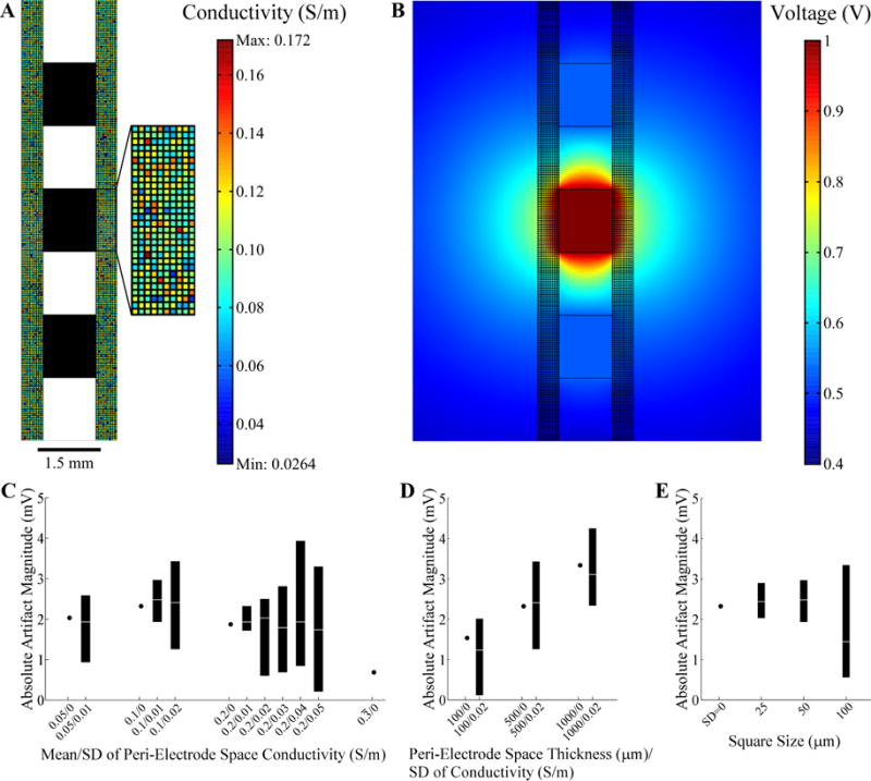
Evaluation of stimulation artifacts using the two-dimensional FEM model of the DBS lead within heterogeneous brain tissue. (A) The peri-electrode space was represented using a checkerboard arrangement, with each square having a random conductivity value (refer to color bar legend), and the remaining brain tissue conductivity was fixed. The average conductivity of the peri-electrode space was 0.1±0.02 S/m (mean ± standard deviation, SD) in the figure. The DBS lead contacts are shown in black. The boundary of the surrounding tissue is not shown. (B) FEM voltage solution resulting from 1 V at contact 1 using the conductivity values shown in (A). (C) The artifact magnitude was calculated for different conductivity values within the peri-electrode space. The thickness of the peri-electrode space was 500 μm and the square size was 50 μm. The range (black bar) and median values (white line) from 10 repeated trials are indicated, except for homogenous conditions (SD=0), in which case a single value is indicated. (D) Artifact magnitude calculated for various thicknesses of peri-electrode space. The SD of conductivity was also varied for each thickness, whereas the mean conductivity was fixed at 0.1 S/m and the square size at 50 μm. (E) Artifact magnitude calculated for different sizes of the peri-electrode space squares. The thickness of the peri-electrode space was fixed at 500 μm and the conductivity was 0.1±0.02 S/m. For reference, the artifact magnitude for the homogenous condition is also indicated.
Results
ECAPs were recorded during thalamic DBS and various characteristics of the signal were then correlated with tremor power. 130 Hz DBS reduced tremor across subjects (Figs. 1B,C), while 10 Hz DBS exacerbated tremor, with few exceptions (Table 4). Administration of sedatives or anesthetics to subjects EP12D, EP13A, EP13F, EP13J, and EP13K may have limited the expected exacerbation of tremor (Table 1). Similarly, little to no tremor was observed in the DBS off condition in several subjects (Table 4), presumably resulting either from a transient microlesion effect in patients undergoing lead implantation surgery or from administration of sedatives or anesthetics. If tremor was determined to be minimal in the DBS off condition at the start of the study, the subject was asked to perform a counting task during each tremor measurement (Table 2) and/or DBS was delivered predominately with a 10 Hz frequency (EP12B, EP13E, and EP13N) to exacerbate tremor. Subsequently, computational models were used to investigate the neural origin of the ECAP signal and the source of the stimulus artifact recorded in some studies.
Table 4.
ECAP and tremor recording conditions and outcomes across subjects. Log10(tremor) was quantified in the DBS off condition as the mean ± standard deviation (SD) across all trials in the tested block, and the change in tremor from the preceeding baseline with 10 or 130 Hz DBS at the clinical voltage (or highest voltage tested if less than the clinical voltage), averaged across cathodic- and anodic-phase first polarities. For change in tremor, negative values indicate tremor reduction and positive values indicate tremor exacerbation with DBS.
| Subject | Recording Condition | ECAP Recording Fidelity | Mean±SD log10(tremor), DBS Off | Change in tremor | |
|---|---|---|---|---|---|
| 130 Hz DBS | 10 Hz DBS | ||||
| EP12A | Chronic | ECAP present with large artifact | 1.15±0.40 | −0.94 | 0.11 |
| EP12B | Chronic | ECAP present with large artifact | −1.55±0.16 | −0.47 | 0.21 |
| EP12C | Chronic | Large artifact | N/A: accelerometer signal contaminated by noise | ||
| EP12D | Chronic | ECAP present | −0.84±0.34 | −0.20 | −0.13 |
| EP12E | Chronic | No amplifier blanking | 0.58+/−1.15 | −1.28 | 2.07 |
| EP13A | Chronic | Large artifact | −1.55+/−0.31 | 0.32 | −0.15 |
| EP13B | Acute | ECAP present | −1.10+/−1.37 | −1.21 | 0.55 |
| EP13C | Acute | Poor fidelity due to bad connection | 0.86+/−0.12 | 0.14 | 0.14 |
| EP13E | Acute | Poor fidelity due to bad connection | −1.60+/−0.13 | −0.29 | 0.19 |
| EP13F | Chronic | Large artifact | 1.13+/−1.00 | −1.22 | −1.43 |
| EP13G | Acute | ECAP present with minimal artifact | −0.11+/−1.01 | −2.33 | 0.11 |
| EP13H | Acute | Poor fidelity due to bad connection | −1.81+/−0.13 | −0.49 | 0.67 |
| EP13I | Acute | ECAP present | −2.25+/−0.14 | 0.15 | 0.27 |
| EP13J | Acute | ECAP present with inimal artifact | 1.96+/−0.27 | −1.07 | −0.12 |
| EP13K | Chronic | Large artifact | 2.78+/−0.24 | −3.46 | −0.06 |
| EP13L | Chronic | ECAP present with minimal artifact | −1.35+/−0.18 | −0.24 | 0.05 |
| EP13N | Acute | ECAP present | −1.08+/−0.46 | −0.65 | 2.45 |
ECAP measurement and characterization
We measured the effects of stimulation polarity, amplitude, and frequency on the ECAP during intraoperative DBS (Fig. 3). The evoked waveform included a primary negative phase (N1), followed by a primary positive phase (P1), and in some cases, a secondary negative phase (N2) and/or secondary positive phase (P2). The ECAP was similar for opposite polarities with symmetric, biphasic stimulation waveforms (20).
Figure 3.
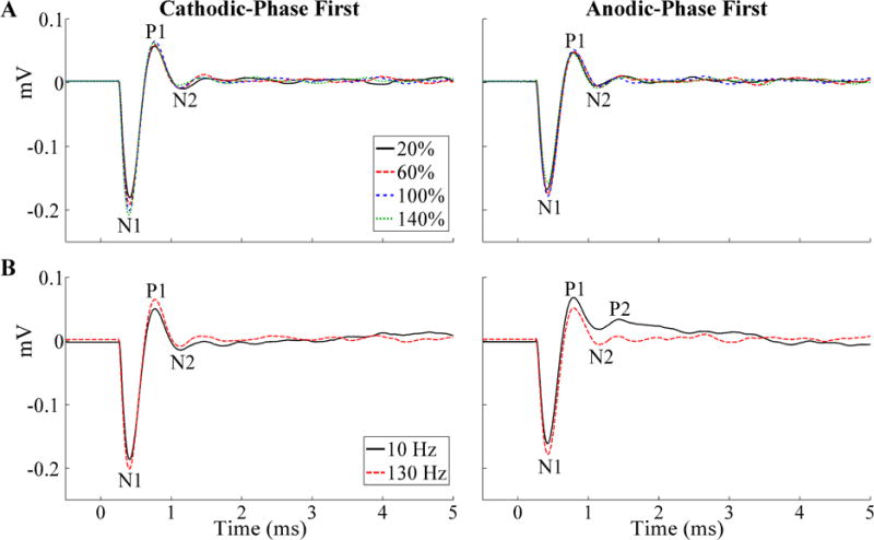
Stimulus-triggered average ECAPs recorded during thalamic DBS across stimulation parameters in EP12D (chronic recording). The ECAP phases are labeled, and the stimulus artifact was negligible. (A) Effect on ECAPs of stimulation amplitude, provided as a percentage of VCLIN, and shown for both cathodic- and anodic-phase first polarities. (B) Effect on ECAPs of stimulation frequency, shown for both polarities at VCLIN.
Recording ECAPs was technically challenging due to the presence of a stimulus artifact, which had variable amplitude between studies (Fig. 4). The ECAP was recorded without any artifact in EP12D (chronic) as well as EP13B, EP13I, and EP13N (acute), and there was a small residual artifact in EP13L (chronic) as well as EP13G and EP13J (acute). A relatively large artifact tail was observed in all remaining studies. Therefore, low artifact recordings were obtained in all 5 acute studies (excluding studies with poor signal fidelity), but in just 2 of 9 chronic studies (Table 4). Averaging the responses for opposite stimulation polarities reduced the stimulus artifact, and revealed an underlying ECAP signal in EP12A and EP12B (chronic). There were negligible ECAP responses even after polarity averaging in EP12C, EP12E, EP13A, EP13K, and EP13F (chronic), except at 20% of VCLIN for the latter.
Figure 4.
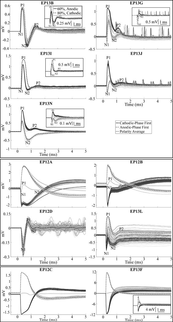
ECAP waveforms recorded during thalamic DBS across subjects, divided into high-fidelity ECAP recordings made in the acute condition (top panel) and chronic condition (middle panel), and two example recordings with large artifacts and negligible ECAP responses (bottom panel). Stimulus-triggered average ECAPs are shown in the bold traces, and single responses are shown as the dark and light gray traces for cathodic- and anodic-phase first polarities, respectively. Other DBS parameters were 130 Hz frequency and an amplitude equal to VCLIN, except for EP12C, EP13J, and EP13L, for which ECAPs are shown with an amplitude that was 60%, 40%, and 59% of VCLIN, respectively, as those were the maximum amplitudes tested in those studies. The insets for EP13B, EP13G, EP13I, and EP13N show ECAP responses for voltages below VCLIN, with cathodic- and anodic-phase first polarities, as well as the polarity average (EP13G only), to demonstrate a more apparent N1 phase. Similarly, the inset for EP13F shows responses for a voltage below VCLIN for cathodic- and anodic-phase first polarities, and the polarity average, to demonstrate the presence of a P1 phase.
When present, the ECAP had a waveform shape characterized by N1-P1-(N2-P2) phases, where N2 and/or P2 were not always present (Fig. 4). The N1 phase was smaller or negligible in acute recordings made with the model 3389 lead compared to that in chronic recordings made with model 3387 or 3389 electrodes. Across subjects and all DBS parameters tested, the peak-to-peak (P-P) ECAP magnitude ranged from 0.08–1.48 mVP-P. For a fixed DBS voltage (~1 V), the ECAP magnitude was larger in the acute condition (range of 0.40–1.33 mVP-P) than in the chronic condition (range of 0.17–0.39 mVP-P). The latency range for the different ECAP phases from the start of the DBS pulse were: N1 at 0.20–0.43 ms, P1 at 0.33–0.8 ms, N2 and P2 at 0.69–2.38 ms. The N1 phase was not as clear in EP13B, EP13G, EP13I, EP13J, or EP13N (acute recordings) at the clinical voltage, but was more evident at lower amplitudes (Fig. 4, insets). The magnitude of the ECAP phases generally increased with higher DBS amplitudes, particularly the N1 and P1 phases (Fig. 3A). Nevertheless, this trend was not always monotonic, as exceeding the clinical voltage led to a decrease in primary phases in some subjects (Figs. 5, 6). Reducing DBS frequency from 130 Hz to 10 Hz increased the magnitude of secondary phases (Fig. 3B) for EP12B, EP12D, EP13L, and EP13N. It is unlikely that this effect resulted from the shorter interpulse interval at 130 Hz (7.7 ms) than at 10 Hz (100 ms), since the longest duration ECAP phase was observed at less than 3 ms after the start of the DBS pulse.
Figure 5.
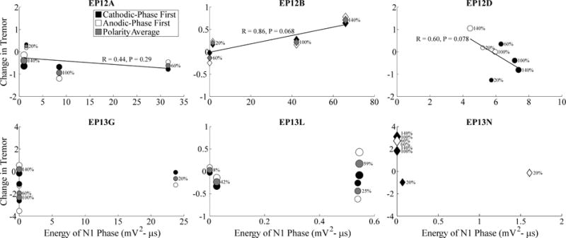
Relationship between changes in tremor and ECAP N1 phase energy across stimulation parameters. Measurements were made across DBS amplitudes, indicated both by the size of the marker and the adjacent text showing amplitude as a percentage of VCLIN, and DBS frequencies, including either 130 Hz or 10 Hz shown with circle and diamond markers, respectively. Further, these data are shown for cathodic- and anodic-phase first polarities with filled and open symbols, respectively. For studies using polarity averaging, one value of the ECAP characteristic is given for both stimulation polarities, and the average of the corresponding tremor measurements across polarities is shown with the gray symbol. Change in tremor was defined such that negative values corresponded to reductions in tremor from baseline, and positive values corresponded to tremor exacerbation. Tremor data was not recorded for EP12D at 130 Hz DBS frequency, 60% of VCLIN, and anodic-phase first polarity, and so the data point is not shown. Despite successful ECAP recording, data is not provided for EP13B and EP13J because a full trial block was not completed, and for EP13I because no tremor was evident in the DBS off condition. Linear regressions were calculated between tremor and ECAP measures, using the polarity average (gray fills) when applicable.
Figure 6.
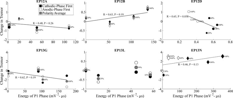
Relationship between changes in tremor and ECAP P1 phase energy across stimulation parameters. Data presentation is otherwise identical to Fig. 5.
Correlation between tremor and ECAP characteristics
We quantified the relationship between tremor and ECAP characteristics across subjects (Figs. 5–7). Tremor was negatively correlated with N1 phase energy at 130 Hz for EP12D (R=0.6, P=0.078) and positively correlated at 10 Hz for EP12B (R=0.86, P=0.068), with near statistical significance. Similarly, tremor was negatively correlated with P1 phase energy at 130 Hz for EP12D (R=0.65, P=0.058), and with secondary phase energy at 130 Hz for EP13G (R=0.87, P=0.067). Finally, the greater energy of secondary phases at 10 Hz compared to 130 Hz observed at the clinical voltage corresponded to increases in tremor.
Figure 7.
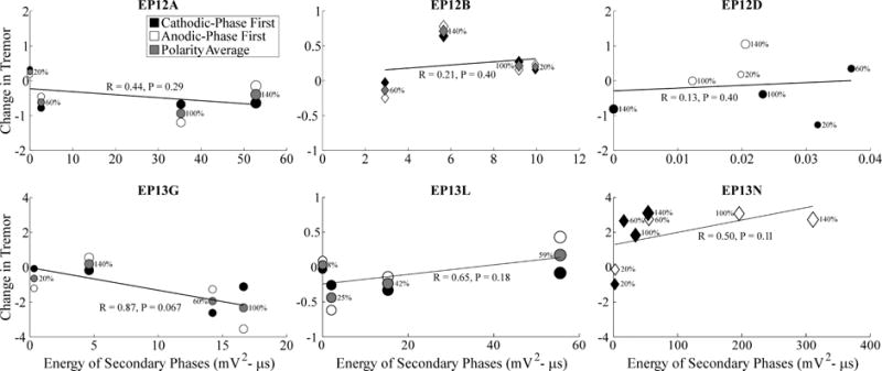
Relationship between changes in tremor and ECAP secondary phase energy across stimulation parameters. Data presentation is otherwise identical to Fig. 5.
Neural origin of the ECAP response
Positioning the model 3387 DBS lead in its original position within Vim (26) resulted in an initial positive ECAP (P1-N1-P2-N2) in the computational model of thalamic DBS, rather than the initial negative ECAP (N1-P1-(N2-P2)) observed in clinical recordings (Fig. 8A). Shifting the position of the clinical lead along its axis by 2 mm dorsally or 6 mm ventrally resulted in an ECAP waveform that was more similar to the experimental signal (Fig. 8A). The former had a N1-P2-N2 waveform shape (P1 not present), whereas the latter had the P1-N1-P2-N2 waveform, but with a relatively small P1 phase. There was a negligible effect when DBS frequency was reduced from 130 Hz to 10 Hz except with the DBS lead positioned ventrally, for which there was a polarity-dependent effect on secondary phases, as seen experimentally (Fig. 8A).
Figure 8.
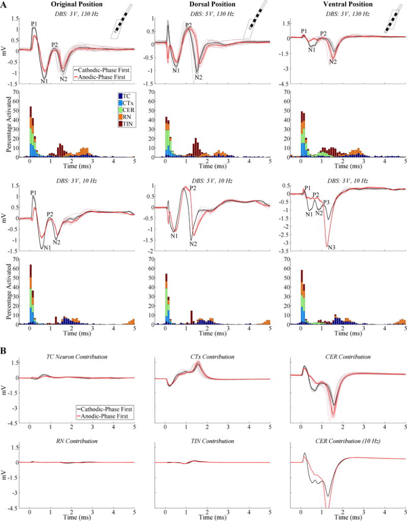
ECAP responses calculated with the model of thalamic DBS using lead model 3387. (A) Model responses for different relative lead positions within the thalamus, including the original position from (26) (left column), dorsal position (center column), and ventral position (right column). The insets in the top row show the FEM geometries of the DBS lead and thalamus from a lateral view. ECAPs are shown for both cathodic- and anodic-phase first polarities, and the corresponding percentage activation of each neural element type in 0.1 ms bins following DBS pulses is shown for cathodic-phase first polarity. DBS amplitudes for each subplot were adjusted to generate similar percentage activation, DBS frequencies were 130 or 10 Hz, and pulse width was fixed at 50 μs/phase. The stimulus-triggered ECAP and single responses are shown in the bold and light traces, respectively, and ECAP phases are labeled. A small stimulus artifact remained with the dorsal lead position following artifact template subtraction, observed as the initial inverted phases for opposite stimulation polarities. (B) The contribution of different neural element types to the composite ECAPs recorded with the ventral lead position at 3 V. The DBS frequency was 130 Hz, unless otherwise designated.
The neural origin of the ECAP signal was determined by analysis of the temporal pattern of neural excitation (Fig. 8A) and by measuring the ECAP contribution from distinct neural elements (Fig. 8B). For 130 Hz DBS, direct activation of neural elements occurred within ~0.9 ms from the start of the DBS pulse, whereas post-synaptic activation of TC, RN, and TIN occurred between ~0.9–3.3 ms from the start of the pulse. Additionally, with the lead in the ventral position, CER activation occurred as late as 1.6 ms. CER received no synaptic input and this delayed CER contribution resulted from direct stimulation in ventral Vim and subsequent propagation to the proximal node of Ranvier in dorsal Vim where activation was detected. Reducing DBS frequency from 130 Hz to 10 Hz shifted timing for direct activation to earlier latencies, reduced post-synaptic activation of RN and TIN, and decreased the latency and increased the synchronization of post-synaptic TC cell activation (i.e., less temporal dispersion of activation times). Recording from different neural elements revealed that CER inputs generated the dominant contribution to the P1-N1-P2-N2 waveform (ventral lead positioning), while contributions from direct excitation of CTx reduced the magnitude of P1, N1, and N2, and shifted P2 to more positive voltages (Fig. 8B). The contributions to the ECAP of TC and TIN elements were relatively small, and those of RN were negligible. Adjustment of DBS frequency predominately affected ECAP contributions from CER inputs, and this drove changes in the composite ECAP between 130 and 10 Hz DBS.
In comparison to the model ECAP waveform recorded with the 3387 lead, that observed with the 3389 lead was similar in shape and magnitude, was affected by a reduction in DBS frequency in a comparable manner, and had an equivalent neural origin (data not shown).
Origin of the stimulus artifact
The clinical recordings exhibited a broad range of stimulus artifact amplitudes, and we hypothesized that these resulted from tissue inhomogeneity and corresponding impedance imbalances between the stimulation contact and each recording contact. Across chronic study recordings, which exhibited large artifacts, and acute recordings, which displayed smaller artifacts, the differences in impedance between the stimulation contact and each recording contact were 25±9% (mean ± SE, n=8) and 6.1±3.4% (n=3), respectively, calculated by normalizing to the average of the two impedance values. The larger imbalance in chronic studies would be expected to increase the differential voltage measured between the two recording contacts during each stimulus pulse, resulting in larger artifacts.
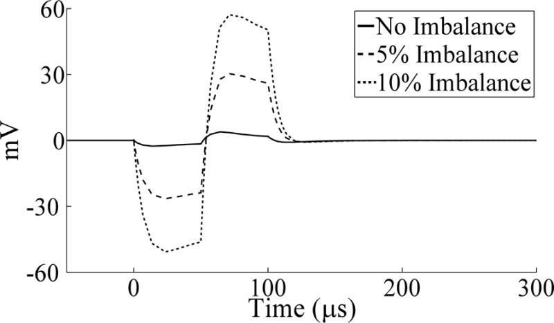
Two computational models were implemented to understand the sources of the stimulus artifact observed in chronic recordings. An electrical circuit equivalent model was used to compare the stimulus artifacts with the initial parameter set (Table 3) to those after alteration of the ETI or bulk tissue properties (Fig. 9). Introducing impedance imbalances between the stimulation contact and each recording contact by decreasing RV01 and increasing RV12 by only 5 or 10% increased the peak-to-peak artifact magnitude by ~9 and 17 times, respectively. Other alterations made to the model, including doubling and halving CDL or RF, or introducing an imbalance in these values between contacts 0 and 2 by up to 50%, had a negligible effect on the artifact. These results suggest that tissue impedance is the dominant determinant of stimulus artifact size, particularly the extent of impedance imbalance between recording contacts.
Figure 9.
Stimulation artifacts calculated with the electrical circuit equivalent model prior to and following unbalancing of volume conductor resistances, by decreasing RV01 and increasing RV12 by the indicated percentage. The waveforms were independent of stimulation frequency (130 Hz shown). An amplifier blanking scheme was not implemented for the model simulations, and so a triphasic artifact waveform was observed.
The second FEM model was used to study the effect on the artifact magnitude of changes in the properties of the peri-electrode space, including heterogeneity in the tissue conductivity. A 0.68 mVP-P artifact was observed when the conductivity of the peri-electrode space was equal to that of the brain tissue ( ), and was generated by the axial discontinuity arising at the lead tip and by the presence of the highly conductive but unused contact 3. There was a non-monotonic trend between the conductivity of a homogenous peri-electrode space and the artifact magnitude. The artifact increased as conductivity of the peri-electrode space was reduced from to 0.1 S/m, before declining at 0.05 S/m (Fig. 2C).
Heterogeneity of the peri-electrode conductivity generated a range of artifact magnitudes across ten replicate simulations. The maximum artifact was always larger than in the homogenous case with the same mean conductivity, the minimum was always less than the homogenous case, and the median value was close to the homogenous case (Fig. 2C). Furthermore, the range of artifact magnitudes generally increased with greater variability in tissue conductivity. Increasing the thickness of the peri-electrode tissue from 100 to 1000 μm increased the artifact magnitude when the peri-electrode tissue was homogenous, and shifted the range of artifact magnitudes towards higher values when the tissue was inhomogeneous (Fig. 2D). Finally, increasing the size of the square division from 25 to 100 μm, thereby changing from a fine to a coarse spatial scale, increased the range of artifact magnitude values across trials (Fig. 2E). These results suggest that chronic changes in neural tissue around the DBS lead, such as the glial encapsulation layer, can increase the artifact magnitude, particularly as the thickness of this layer increases, and that heterogeneity in the conductivity can further increase the artifact magnitude.
Discussion
ECAPs were recorded from implanted electrodes during thalamic DBS in subjects with tremor. There was large subject-to-subject variation in stimulus artifact amplitude, with larger artifacts typically observed in chronic recordings, and model-based analysis revealed that the larger artifacts were due to imbalances in the tissue impedance between the contacts, perhaps arising from chronic glial encapsulation of the lead. High fidelity ECAP recordings obtained from both acute and chronically implanted electrodes revealed that specific phase characteristics of the signal varied systematically with stimulation parameters and were correlated with changes in tremor in some patients with near statistical significance. Further, results from this study suggest that excitation of cerebellar afferents during DBS is important for reduction of motor symptoms, consistent with prior findings (26, 37–39). The demonstration of high-fidelity recordings of ECAPs from both acutely and chronically implanted DBS leads, as well as the identification of ECAP characteristics correlated with motor symptoms, suggest that ECAPs may be a suitable feedback signal for automated selection and optimization of stimulation parameters in both the acute phase, and possibly chronic phase.
The neural source of LFPs is typically attributed to post-synaptic potentials (40), whereas the clinical ECAP response appeared to be generated by direct axonal activation. The latter is in agreement with preclinical results, in which direct neuronal activation generated primary ECAP phases, as validated by administration of agents that blocked excitatory synaptic transmission (20). Action potential initiation and propagation generates strong but short duration extracellular fields, and the synchronous activation of an axonal population following each DBS pulse would be expected to make substantial contributions to ECAP recordings, particularly at this short latency (40).
ECAP waveform and the effect of stimulation parameters
The ECAP waveform generally exhibited N1-P1-(N2-P2) phases, although in acute recordings made with the model 3389 lead, the N1 phase was typically not as evident at the higher stimulation amplitudes. Since this N1 phase was observed in the computational model with the 3387 and 3389 electrodes, its smaller amplitude seen experimentally was more likely a result of the differences in recording time point. ECAP signals recorded in preclinical experiments were inverted, with primary P1-N1 phases followed by secondary P2-N2 phases (20). We reproduced the clinical ECAP polarity in the model only with ventral or dorsal positioning of the clinical DBS lead within the thalamic nucleus (Fig. 8A). Routine clinical lead implantation for thalamic DBS typically involves placement of contact 0 near or below the ventral border of Vim, and the model indicated that the specific ECAP shape observed experimentally was dependent this lead location. The effect of lead position may have also accounted for some of the variability between subjects in the recorded ECAPs.
The experimental ECAP magnitude was larger in the acute stage than in the chronic stage, with DBS amplitude approximately constant. The external counter electrode used in conjunction with chronically implanted electrodes, but not acutely implanted electrodes, may have resulted in a voltage drop across the skin that reduced voltages in the brain tissue, ultimately decreasing neural activation. Also, glial scar formation after chronic lead implantation leads to axonal cell loss near the lead (41, 42), and could have reduced the ECAP magnitude, as suggested by prior modeling work (29). Additionally, the glial encapsulation layer could potentially isolate recording contacts from the surrounding axons and further diminish the ECAP. Finally, for chronic recordings, the highest fidelity responses were recorded in subjects EP12A, EP12B, EP12D, and EP13L, who did not receive any anesthesia or other medications during surgery. Conversely, ECAPs were not observed in any of the subjects who received anesthetics during surgery.
The ECAP varied systematically with stimulation parameters (Figs. 3, 5–7). Responses were similar for opposite stimulation polarities, as observed in our previous work (20), and this enabled polarity averaging to remove the stimulus artifact, when necessary. This is in contrast to use of asymmetric biphasic stimulation waveforms with opposite polarities, which would be expected to generate differential neural activation patterns (43, 44) and clinical outcomes (45). There was a non-monotonic relationship between ECAP magnitude and DBS amplitude. The ECAP magnitude is thought to reflect a spatial average of neural activation over a volume (20, 29), and the model indicated that the decline in N1 and N2 at the highest DBS amplitudes resulted from greater activation of cortical inputs, which reduced the negative phases through destructive interference. Exploring a broader range of DBS amplitudes would have better clarified the input-output characteristics of the ECAP, although we limited the maximum tested amplitude to mitigate potential side effects. Decreasing DBS frequency from 130 Hz to 10 Hz increased the magnitude of N2 and/or P2, and our previous study suggested that the increased post-synaptic synchronization of TC cells at low frequencies increased the magnitude of secondary phases (20). While this increased TC synchronization was still evident with lower DBS frequencies (Fig. 8A), the corresponding effect on the ECAP was masked by the much larger contribution from directly excited cerebellar afferents, which were also affected by frequency (Fig. 8B).
Relationship between ECAP and clinical effectiveness
Tremor was generally reduced with 130 Hz DBS and exacerbated at 10 Hz (46). For high-frequency DBS, we typically observed a non-monotonic relationship between tremor and stimulation voltage, in which increasing the amplitude initially led to greater reductions in tremor before reversing beyond some optimal voltage (Fig. 5). This could have been caused by the activation of more distant, tremor aggravating brain areas at higher voltages (47).
The relationship between the ECAP signal and tremor provides insights into mechanisms of DBS and reveals a potential feedback signal for automated parameter tuning. Increasing ECAP phase energy was related to reductions in tremor at 130 Hz and exacerbation of tremor at 10 Hz with near statistical significance in some patients. Since the ECAP signal energy provides a measure of the extent of neural activation (20), these results suggest that DBS must activate a sufficient volume of tissue for clinical benefit at 130 Hz, or for symptom exacerbation at 10 Hz. The thalamic DBS model revealed that cerebellar afferents were the dominant contributors to the ECAP response, and since the energy of ECAP phases was correlated with tremor in some patients with near statistical significance, this suggests that activation of cerebellar inputs is critical to tremor suppression by DBS. This is consistent with the findings that activation of cerebellothalamic afferents suppressed tremor in ET patients by overriding pathological bursting activity (26), and that lead contacts in the subthalamic area ventral to Vim may be equally effective to contacts within Vim (37–39), depending on the specific course of the cerebellar efferents as they cross near the base of Vim and synapse in the ventral oralis posterior (VOP) nucleus of the thalamus (48).
The ECAP could provide a feedback control signal for automated adjustment of stimulation parameters in closed-loop DBS systems. For example, DBS amplitude could be adjusted to attain pre-determined ECAP phase energy threshold values. However, the absolute phase energy values varied by an order of magnitude between subjects, and the relationship between ECAP phase energy and tremor varied across subjects (Figs. 5–7). Therefore, the threshold values used to set DBS parameters may be subject specific, and may need to be specified as a normalized value of some maximum signal energy within subjects. The dependence of ECAP waveform shape on lead location suggests that the ECAP might also be used to target a brain region for implantation and to select contact(s) for stimulation.
Source of the stimulus artifact
The stimulus artifact was highly variable between studies, and in some cases interfered with the ECAP signal, as seen also in cochlear ECAP measurements (18). A possible trend was observed in which ECAPs were observed in subjects with clinical voltage settings less than 4 V, but not in subjects with higher clinical voltages (Tables 2, 4). The larger stimulus artifact associated with higher stimulation amplitudes may have masked the ECAP response. Moreover, the observation that the artifact was minimal in the acute condition, in both clinical and preclinical studies (16, 20), suggested that changes in the cellular milieu around the chronically implanted DBS lead influenced the stimulus artifact. Additionally, chronic DBS may have generated imbalances in electrode impedance between stimulated and non-stimulated contacts.
The peri-electrode space is filled with cerebrospinal fluid soon after acute implantation (34) and is subsequently surrounded by a thin glial scar (41, 49) that increases the tissue impedance (50, 51). Further, protein and cell adsorption onto the contact surfaces can influence the double-layer capacitance, and thereby the impedance of the ETI (50, 51). The electrical circuit equivalent model suggested that imbalances of only 5–10% in the resistance between the stimulation contact and each recording contact led to substantial increases in the artifact magnitude. The FEM-based model corroborated this finding, also indicating that increases in the thickness of the encapsulation layer led to larger artifacts. Further, greater heterogeneity within the encapsulation layer increased the range of artifact magnitudes, perhaps reflecting the range of artifact magnitudes observed across subjects. The imbalance in tissue impedance between contacts could result from applying chronic stimulation at just one of the two contacts used for ECAP recording, since this would reduce the impedance in the chronic condition by polarizing the surface(s) of clinical stimulating contact(s), causing attached proteins and cells to desorb (52–54). Differences in the brain composition and tissue conductivity near each contact could also contribute to the impedance imbalances. Regardless, these results indicate that the cellular milieu near the DBS lead plays a critical role in determining the size of the stimulus artifact observed in chronic studies, and thus the fidelity of ECAPs recorded during DBS.
Although the relatively large and variable stimulus artifact magnitude could adversely affect long-term recording fidelity in a closed-loop DBS system by masking the ECAP response, there are several potential solutions for reducing the chronic artifact magnitude. First, sending sub-threshold, intermittent stimulation pulses to recording contacts could mitigate differences in impedance imbalances on the lead array. Second, the input impedance of the recording circuitry could be adjusted to compensate for impedance imbalances between contacts.
Study limitations
There were several limitations in both the experimental and computational aspects of this work. First, the experimental contact configuration often differed from that used clinically and identified by a neurologist as the most effective for therapy. We used the monopolar stimulation – symmetric recording contact configuration to minimize the stimulus artifact (16), and thus only contacts 1 or 2 were used as the stimulation contact. Second, the symmetrical, biphasic DBS waveform, used to minimize the duration of the stimulation artifact, did not match the asymmetrical waveform used clinically in IPGs (55). Third, a voltage drop across the skin was likely generated with the use of a surface counter electrode in the chronic condition (56), which would result in a reduction in the voltage across the brain tissue. Nevertheless, sufficient voltage was still delivered to the thalamus to generate ECAPs, changes in tremor, and paresthesias. All three of these limitations could reduce the effectiveness of DBS in treating tremor, compared to clinical DBS delivered with an IPG.
Other limitations included the short duration of DBS prior to the assessment of motor symptoms, the short interval between trials, and conducting only a single trial at each DBS setting in most studies. While tremor reduction following the onset of DBS typically occurs within a few seconds (57), our trial design may have underestimated the magnitude of changes in tremor after 30 s of stimulation. Nevertheless, similarly short trial lengths have been used previously in testing the effects of parameter settings (58), and are used routinely for intraoperative testing and post-operative tuning (59). The washout of DBS effects on tremor occurs over seconds to minutes, with 85% of the return in tremor after cessation of DBS occurring within 5 minutes (57). However, using longer trial lengths, longer intervals between trials, or replicate trials would have resulted in the study becoming too long to conduct during an intraoperative procedure.
The correlations between tremor and ECAP signal characteristics were variable and not statistically significant. Testing a larger number of DBS parameter combinations (e.g., stimulation amplitudes) in a given study would have increased the number of data points used in the correlation, and thus, the statistical power. Additionally, the relationship between tremor and ECAP characteristics may have been non-linear, but we restricted our analysis to linear regression models due to the small number of data points (4) available for fitting for most patients. However, we were limited in the number of trials that could be conducted within the intraoperative setting.
There were also limitations in the computational models, which have been discussed previously (16, 20). Briefly, in the thalamic DBS model, the position of the DBS lead within Vim and trajectories of neural elements were approximations, and using more accurate representations may have changed neural activation and the model ECAP response. This may explain the smaller positive phase observed in the model compared to the experimental ECAP recordings. Further, this model did not account for the ETI, tissue capacitance, or tissue inhomogeneities, which could filter DBS potentials (28, 53, 60–62) and the ECAP signal (40, 63, 64). Finally, the model was restricted to representation of Vim, and any lead position dependent contributions of other neural structures were not represented.
The electrical circuit equivalent model used geometrical approximations to calculate the resistance and capacitance of the medium, and did not account for the capacitive coupling between stimulating and recording leads (56, 65), the capacitance of the medium directly between two DBS contacts, or the frequency dependence of tissue permittivity (66).
Supplementary Material
Figure S1. Intraoperative recording of ECAPs during DBS. (A) Diagram of the recording instrumentation. Stimulation was delivered using a monopolar, AC-coupled configuration between a DBS contact and distant counter electrode. The PhotoMOS relay (AQV212(A)) opened after each DBS pulse to limit discharge of capacitive charge from the electrode-tissue interface through the parallel 10 kΩ resistor, rather than through the low-impedance stimulator. ECAPs were recorded from the two contacts adjacent to the stimulating contact, and were amplified by a differential SR560 preamplifier stage (A1) and two subsequent SR560 amplifier stages (A2 and A3), which also filtered the signal. To reduce the size of the stimulus artifact, antiparallel diodes (IN4154) were placed at the inputs to A2 and A3, grounding the line if the voltage exceeded ±0.7 V, and the latter two stages were internally blanked during each pulse and the subsequent 60 μs. All amplifiers were AC-coupled at the front-end, either externally (A1) or internally (A2 and A3), and anti-series current limiting diodes (CCL0035) were placed at the inputs to the first amplifier stage. (B) Diagram of subject positioning and electrode placement for the intraoperative study. For subjects undergoing IPG implantation surgery, the connection to the DBS lead was made through an incision in the chest, and the counter electrode (CE) was typically placed on the chest opposite the surgical site. Alternatively, for subjects undergoing DBS electrode implantation, the connection to the DBS lead was made through the cranial burr hole, and the CE was a retractor at the cranial burr hole or the implant cannula. The recording reference electrode (RE) was typically placed on the thigh ipsilateral to stimulation. The accelerometer used for tremor measurement was taped to the hand contralateral to stimulation. Modified with permission from (22).
Figure S2. Computational model of ECAP recording during thalamic DBS. (A) The FEM model included a three-dimensional representation of the DBS electrode within a prism representation of the Vim nucleus of the thalamus, all encompassed within a large volume representing surrounding brain tissue (not shown). The model contained 500 thalamocortical (TC) neurons, with soma locations indicated by the dots, and pre-synaptic inputs from the cortex (CTx), cerebellum (CER), reticular nucleus (RN) and thalamic interneurons (TIN). The anatomical locations of the elements are shown for one neural unit, with the TC neuron and pre-synaptic inputs represented by the black shapes and gray lines, respectively. (B) Diagram of the synaptic connections made between neural elements in the multi-compartment cable models. These included glutamatergic and GABAergic synapses on the TC soma and dendritic tree, and excitatory 1:1 synapses between neural elements implemented using virtual axons. Used with permission from (20).
HIGHLIGHTS.
We conducted recordings of evoked potentials (ECAPs) generated by thalamic deep brain stimulation using the same brain lead used to deliver stimulation
Simultaneous electrical recordings and tremor recordings were made in patients who were either undergoing surgery for initial electrode implantation or replacement of their internal pulse generator.
ECAP recordings revealed that specific phase characteristics of the signal varied systematically with stimulation parameters.
Quantitative model-based analysis revealed that large subject-to-subject variation in stimulus artifact was caused by glial encapsulation of the electrode, resulting in imbalances in the tissue impedance between the contacts.
Demonstrated that ECAPs can be recorded in the clinical setting and may provide a feedback control signal for adjustment of stimulation parameters.
Acknowledgments
The authors would like to thank Dr. Nandan Lad, Dr. Jon Willie, and Dr. Otis Smart for assistance in data collection. This work was supported by NIH F31 NS070460 and NIH R01 NS079312.
Footnotes
Publisher's Disclaimer: This is a PDF file of an unedited manuscript that has been accepted for publication. As a service to our customers we are providing this early version of the manuscript. The manuscript will undergo copyediting, typesetting, and review of the resulting proof before it is published in its final citable form. Please note that during the production process errors may be discovered which could affect the content, and all legal disclaimers that apply to the journal pertain.
Financial Disclosures
REG receives research funding from Medtronic, which is developing products related to the research described in this paper. In addition, REG serves as a consultant to Medtronic and receives compensation for these services. The terms of this arrangement have been reviewed and approved by Emory University in accordance with its conflict of interest policies.
References
- 1.Benabid AL, Pollak P, Gervason C, Hoffmann D, Gao DM, Hommel M, et al. Long-term suppression of tremor by chronic stimulation of the ventral intermediate thalamic nucleus. Lancet. 1991 Feb 16;337(8738):403–6. doi: 10.1016/0140-6736(91)91175-t. [DOI] [PubMed] [Google Scholar]
- 2.Gross RE, Lozano AM. Advances in neurostimulation for movement disorders. Neurol Res. 2000 Apr;22(3):247–58. doi: 10.1080/01616412.2000.11740667. [DOI] [PubMed] [Google Scholar]
- 3.Ondo WG, Bronte-Stewart H. The North American survey of placement and adjustment strategies for deep brain stimulation. Stereotact Funct Neurosurg. 2005;83(4):142–7. doi: 10.1159/000088654. [DOI] [PubMed] [Google Scholar]
- 4.Okun MS, Tagliati M, Pourfar M, Fernandez HH, Rodriguez RL, Alterman RL, et al. Management of referred deep brain stimulation failures: a retrospective analysis from 2 movement disorders centers. Arch Neurol. 2005 Aug;62(8):1250–5. doi: 10.1001/archneur.62.8.noc40425. [DOI] [PubMed] [Google Scholar]
- 5.Pahwa R, Lyons KE, Wilkinson SB, Simpson RK, Jr, Ondo WG, Tarsy D, et al. Long-term evaluation of deep brain stimulation of the thalamus. J Neurosurg. 2006 Apr;104(4):506–12. doi: 10.3171/jns.2006.104.4.506. [DOI] [PubMed] [Google Scholar]
- 6.Kuncel AM, Grill WM. Selection of stimulus parameters for deep brain stimulation. Clin Neurophysiol. 2004 Nov;115(11):2431–41. doi: 10.1016/j.clinph.2004.05.031. [DOI] [PubMed] [Google Scholar]
- 7.Rosin B, Slovik M, Mitelman R, Rivlin-Etzion M, Haber SN, Israel Z, et al. Closed-loop deep brain stimulation is superior in ameliorating parkinsonism. Neuron. 2011 Oct 20;72(2):370–84. doi: 10.1016/j.neuron.2011.08.023. [DOI] [PubMed] [Google Scholar]
- 8.Williams JC, Rennaker RL, Kipke DR. Long-term neural recording characteristics of wire microelectrode arrays implanted in cerebral cortex. Brain Res Brain Res Protoc. 1999 Dec;4(3):303–13. doi: 10.1016/s1385-299x(99)00034-3. [DOI] [PubMed] [Google Scholar]
- 9.Brown P, Williams D. Basal ganglia local field potential activity: character and functional significance in the human. Clin Neurophysiol. 2005 Nov;116(11):2510–9. doi: 10.1016/j.clinph.2005.05.009. [DOI] [PubMed] [Google Scholar]
- 10.Brown P. Oscillatory nature of human basal ganglia activity: relationship to the pathophysiology of Parkinson’s disease. Mov Disord. 2003 Apr;18(4):357–63. doi: 10.1002/mds.10358. [DOI] [PubMed] [Google Scholar]
- 11.Pedrosa DJ, Reck C, Florin E, Pauls KA, Maarouf M, Wojtecki L, et al. Essential tremor and tremor in Parkinson’s disease are associated with distinct ‘tremor clusters’ in the ventral thalamus. Exp Neurol. 2012 Oct;237(2):435–43. doi: 10.1016/j.expneurol.2012.07.002. [DOI] [PubMed] [Google Scholar]
- 12.Afshar P, Khambhati A, Stanslaski S, Carlson D, Jensen R, Linde D, et al. A translational platform for prototyping closed-loop neuromodulation systems. Front Neural Circuits. 2012;6:117. doi: 10.3389/fncir.2012.00117. [DOI] [PMC free article] [PubMed] [Google Scholar]
- 13.Chen CC, Pogosyan A, Zrinzo LU, Tisch S, Limousin P, Ashkan K, et al. Intra-operative recordings of local field potentials can help localize the subthalamic nucleus in Parkinson’s disease surgery. Exp Neurol. 2006 Mar;198(1):214–21. doi: 10.1016/j.expneurol.2005.11.019. [DOI] [PubMed] [Google Scholar]
- 14.Miyagi Y, Okamoto T, Morioka T, Tobimatsu S, Nakanishi Y, Aihara K, et al. Spectral analysis of field potential recordings by deep brain stimulation electrode for localization of subthalamic nucleus in patients with Parkinson’s disease. Stereotact Funct Neurosurg. 2009;87(4):211–8. doi: 10.1159/000225974. [DOI] [PubMed] [Google Scholar]
- 15.Yoshida F, Martinez-Torres I, Pogosyan A, Holl E, Petersen E, Chen CC, et al. Value of subthalamic nucleus local field potentials recordings in predicting stimulation parameters for deep brain stimulation in Parkinson’s disease. J Neurol Neurosurg Psychiatry. 2010 Aug;81(8):885–9. doi: 10.1136/jnnp.2009.190918. [DOI] [PubMed] [Google Scholar]
- 16.Kent AR, Grill WM. Recording evoked potentials during deep brain stimulation: development and validation of instrumentation to suppress the stimulus artefact. J Neural Eng. 2012 Jun;9(3):036004. doi: 10.1088/1741-2560/9/3/036004. [DOI] [PMC free article] [PubMed] [Google Scholar]
- 17.Jeon EK, Brown CJ, Etler CP, O’Brien S, Chiou LK, Abbas PJ. Comparison of electrically evoked compound action potential thresholds and loudness estimates for the stimuli used to program the Advanced Bionics cochlear implant. J Am Acad Audiol. 2010 Jan;21(1):16–27. doi: 10.3766/jaaa.21.1.3. [DOI] [PMC free article] [PubMed] [Google Scholar]
- 18.Miller CA, Brown CJ, Abbas PJ, Chi SL. The clinical application of potentials evoked from the peripheral auditory system. Hear Res. 2008 Aug;242(1–2):184–97. doi: 10.1016/j.heares.2008.04.005. [DOI] [PubMed] [Google Scholar]
- 19.Gorman R, Parker J, Karantonis D, Single P, Obradovic M, Laird J, et al., editors. Neural recordings for feedback control of spinal cord stimulation: reduction of paraesthesia variability. International Neuromodulation Society; Berlin, Germany: 2013. [Google Scholar]
- 20.Kent AR, Grill WM. Neural origin of evoked potentials during thalamic deep brain stimulation. J Neurophysiol. 2013;110(4):826–43. doi: 10.1152/jn.00074.2013. [DOI] [PMC free article] [PubMed] [Google Scholar]
- 21.Ferrara JM, Adam OR, Ondo WG. Treatment of fragile-X-associated tremor/ataxia syndrome with deep brain stimulation. Mov Disord. 2009 Jan 15;24(1):149–51. doi: 10.1002/mds.22354. [DOI] [PubMed] [Google Scholar]
- 22.Swan BD, Grill WM, Turner DA. Investigation of deep brain stimulation mechanisms during implantable pulse generator replacement surgery. Neuromodulation. 2013 Oct 7; doi: 10.1111/ner.12123. [DOI] [PMC free article] [PubMed] [Google Scholar]
- 23.Wei XF, Grill WM. Current density distributions, field distributions and impedance analysis of segmented deep brain stimulation electrodes. J Neural Eng. 2005 Dec;2(4):139–47. doi: 10.1088/1741-2560/2/4/010. [DOI] [PubMed] [Google Scholar]
- 24.Kuncel AM, Cooper SE, Wolgamuth BR, Grill WM. Amplitude- and frequency-dependent changes in neuronal regularity parallel changes in tremor With thalamic deep brain stimulation. IEEE Trans Neural Syst Rehabil Eng. 2007 Jun;15(2):190–7. doi: 10.1109/TNSRE.2007.897004. [DOI] [PubMed] [Google Scholar]
- 25.Brown CJ, Abbas PJ. Electrically evoked whole-nerve action potentials: parametric data from the cat. J Acoust Soc Am. 1990 Nov;88(5):2205–10. doi: 10.1121/1.400117. [DOI] [PubMed] [Google Scholar]
- 26.Birdno MJ, Kuncel AM, Dorval AD, Turner DA, Gross RE, Grill WM. Stimulus features underlying reduced tremor suppression with temporally patterned deep brain stimulation. J Neurophysiol. 2012 Jan;107(1):364–83. doi: 10.1152/jn.00906.2010. [DOI] [PMC free article] [PubMed] [Google Scholar]
- 27.Moffitt MA, McIntyre CC. Model-based analysis of cortical recording with silicon microelectrodes. Clin Neurophysiol. 2005 Sep;116(9):2240–50. doi: 10.1016/j.clinph.2005.05.018. [DOI] [PubMed] [Google Scholar]
- 28.Yousif N, Bayford R, Liu X. The influence of reactivity of the electrode-brain interface on the crossing electric current in therapeutic deep brain stimulation. Neuroscience. 2008 Oct 15;156(3):597–606. doi: 10.1016/j.neuroscience.2008.07.051. [DOI] [PMC free article] [PubMed] [Google Scholar]
- 29.Kent AR, Grill WM. Analysis of deep brain stimulation electrode characteristics for neural recording. J Neural Eng. 2014;11(4):1–12. doi: 10.1088/1741-2560/11/4/046010. [DOI] [PMC free article] [PubMed] [Google Scholar]
- 30.Helmholtz HLF. Ueber einige gesetze der vertheilung elektrischer strome in korperlichen leitern mit anwendung auf die thierisch-electrischen versuche. Ann Physik Chemie. 1853;89:354–77. [Google Scholar]
- 31.Hirai T, Ohye C, Nagaseki Y, Matsumura M. Cytometric analysis of the thalamic ventralis intermedius nucleus in humans. J Neurophysiol. 1989 Mar;61(3):478–87. doi: 10.1152/jn.1989.61.3.478. [DOI] [PubMed] [Google Scholar]
- 32.Briaire JJ, Frijns JH. Unraveling the electrically evoked compound action potential. Hear Res. 2005 Jul;205(1–2):143–56. doi: 10.1016/j.heares.2005.03.020. [DOI] [PubMed] [Google Scholar]
- 33.Wei XF, Grill WM. Impedance characteristics of deep brain stimulation electrodes in vitro and in vivo. J Neural Eng. 2009 Aug;6(4):1–9. doi: 10.1088/1741-2560/6/4/046008. [DOI] [PMC free article] [PubMed] [Google Scholar]
- 34.Yousif N, Bayford R, Wang S, Liu X. Quantifying the effects of the electrode-brain interface on the crossing electric currents in deep brain recording and stimulation. Neuroscience. 2008 Mar 27;152(3):683–91. doi: 10.1016/j.neuroscience.2008.01.023. [DOI] [PMC free article] [PubMed] [Google Scholar]
- 35.Butson CR, Maks CB, McIntyre CC. Sources and effects of electrode impedance during deep brain stimulation. Clin Neurophysiol. 2006 Feb;117(2):447–54. doi: 10.1016/j.clinph.2005.10.007. [DOI] [PMC free article] [PubMed] [Google Scholar]
- 36.Fishler MG. Syncytial heterogeneity as a mechanism underlying cardiac far-field stimulation during defibrillation-level shocks. J Cardiovasc Electrophysiol. 1998 Apr;9(4):384–94. doi: 10.1111/j.1540-8167.1998.tb00926.x. [DOI] [PubMed] [Google Scholar]
- 37.Coenen VA, Madler B, Schiffbauer H, Urbach H, Allert N. Individual fiber anatomy of the subthalamic region revealed with diffusion tensor imaging: a concept to identify the deep brain stimulation target for tremor suppression. Neurosurgery. 2011 Apr;68(4):1069–75. doi: 10.1227/NEU.0b013e31820a1a20. discussion 75–6. [DOI] [PubMed] [Google Scholar]
- 38.Keane M, Deyo S, Abosch A, Bajwa JA, Johnson MD. Improved spatial targeting with directionally segmented deep brain stimulation leads for treating essential tremor. J Neural Eng. 2012 Aug;9(4):1–10. doi: 10.1088/1741-2560/9/4/046005. [DOI] [PMC free article] [PubMed] [Google Scholar]
- 39.Sandvik U, Lars-Owe K, Anders L, Patric B. Thalamic and Subthalamic Deep Brain Stimulation for Essential Tremor: Where Is the Optimal Target? Neurosurgery. 2011 Sep 27;70(4):840–6. doi: 10.1227/NEU.0b013e318236a809. [DOI] [PubMed] [Google Scholar]
- 40.Buzsaki G, Anastassiou CA, Koch C. The origin of extracellular fields and currents–EEG, ECoG, LFP and spikes. Nat Rev Neurosci. 2012 Jun;13(6):407–20. doi: 10.1038/nrn3241. [DOI] [PMC free article] [PubMed] [Google Scholar]
- 41.Henderson JM, Pell M, O’Sullivan DJ, McCusker EA, Fung VS, Hedges P, et al. Postmortem analysis of bilateral subthalamic electrode implants in Parkinson’s disease. Mov Disord. 2002 Jan;17(1):133–7. doi: 10.1002/mds.1261. [DOI] [PubMed] [Google Scholar]
- 42.McConnell GC, Rees HD, Levey AI, Gutekunst CA, Gross RE, Bellamkonda RV. Implanted neural electrodes cause chronic, local inflammation that is correlated with local neurodegeneration. J Neural Eng. 2009 Oct;6(5):1–12. doi: 10.1088/1741-2560/6/5/056003. [DOI] [PubMed] [Google Scholar]
- 43.McIntyre CC, Grill WM. Selective microstimulation of central nervous system neurons. Ann Biomed Eng. 2000 Mar;28(3):219–33. doi: 10.1114/1.262. [DOI] [PubMed] [Google Scholar]
- 44.Wang Q, Millard DC, Zheng HJ, Stanley GB. Voltage-sensitive dye imaging reveals improved topographic activation of cortex in response to manipulation of thalamic microstimulation parameters. J Neural Eng. 2012 Apr;9(2):1–14. doi: 10.1088/1741-2560/9/2/026008. [DOI] [PMC free article] [PubMed] [Google Scholar]
- 45.Yousif N, Pavese N, Naushahi MJ, Nandi D, Bain PG. Reversing the polarity of bipolar stimulation in deep brain stimulation for essential tremor: A theoretical explanation for a useful clinical intervention. Neurocase. 2012 Sep 24; doi: 10.1080/13554794.2012.713495. [DOI] [PubMed] [Google Scholar]
- 46.Birdno MJ, Grill WM. Mechanisms of deep brain stimulation in movement disorders as revealed by changes in stimulus frequency. Neurotherapeutics. 2008 Jan;5(1):14–25. doi: 10.1016/j.nurt.2007.10.067. [DOI] [PMC free article] [PubMed] [Google Scholar]
- 47.Cooper SE, Kuncel AM, Wolgamuth BR, Rezai AR, Grill WM. A model predicting optimal parameters for deep brain stimulation in essential tremor. J Clin Neurophysiol. 2008 Oct;25(5):265–73. doi: 10.1097/WNP.0b013e318182ed44. [DOI] [PMC free article] [PubMed] [Google Scholar]
- 48.Gallay MN, Jeanmonod D, Liu J, Morel A. Human pallidothalamic and cerebellothalamic tracts: anatomical basis for functional stereotactic neurosurgery. Brain Struct Funct. 2008 Aug;212(6):443–63. doi: 10.1007/s00429-007-0170-0. [DOI] [PMC free article] [PubMed] [Google Scholar]
- 49.Haberler C, Alesch F, Mazal PR, Pilz P, Jellinger K, Pinter MM, et al. No tissue damage by chronic deep brain stimulation in Parkinson’s disease. Ann Neurol. 2000 Sep;48(3):372–6. [PubMed] [Google Scholar]
- 50.Lempka SF, Miocinovic S, Johnson MD, Vitek JL, McIntyre CC. In vivo impedance spectroscopy of deep brain stimulation electrodes. J Neural Eng. 2009 Aug;6(4):1–11. doi: 10.1088/1741-2560/6/4/046001. [DOI] [PMC free article] [PubMed] [Google Scholar]
- 51.Newbold C, Richardson R, Millard R, Huang C, Milojevic D, Shepherd R, et al. Changes in biphasic electrode impedance with protein adsorption and cell growth. J Neural Eng. 2010 Oct;7(5):1–11. doi: 10.1088/1741-2560/7/5/056011. [DOI] [PMC free article] [PubMed] [Google Scholar]
- 52.Cheung T, Nuno M, Hoffman M, Katz M, Kilbane C, Alterman R, et al. Longitudinal Impedance Variability in Patients with Chronically Implanted DBS Devices. Brain Stimul. 2013 Apr 12; doi: 10.1016/j.brs.2013.03.010. [DOI] [PubMed] [Google Scholar]
- 53.Lempka SF, Johnson MD, Miocinovic S, Vitek JL, McIntyre CC. Current-controlled deep brain stimulation reduces in vivo voltage fluctuations observed during voltage-controlled stimulation. Clin Neurophysiol. 2010 Dec;121(12):2128–33. doi: 10.1016/j.clinph.2010.04.026. [DOI] [PMC free article] [PubMed] [Google Scholar]
- 54.Newbold C, Richardson R, Millard R, Seligman P, Cowan R, Shepherd R. Electrical stimulation causes rapid changes in electrode impedance of cell-covered electrodes. J Neural Eng. 2011 Jun;8(3):1–13. doi: 10.1088/1741-2560/8/3/036029. [DOI] [PMC free article] [PubMed] [Google Scholar]
- 55.Miocinovic S, Lempka SF, Russo GS, Maks CB, Butson CR, Sakaie KE, et al. Experimental and theoretical characterization of the voltage distribution generated by deep brain stimulation. Exp Neurol. 2009 Mar;216(1):166–76. doi: 10.1016/j.expneurol.2008.11.024. [DOI] [PMC free article] [PubMed] [Google Scholar]
- 56.McGill KC, Cummins KL, Dorfman LJ, Berlizot BB, Leutkemeyer K, Nishimura DG, et al. On the nature and elimination of stimulus artifact in nerve signals evoked and recorded using surface electrodes. IEEE Trans Biomed Eng. 1982 Feb;29(2):129–37. doi: 10.1109/TBME.1982.325019. [DOI] [PubMed] [Google Scholar]
- 57.Beuter A, Titcombe MS. Modulation of tremor amplitude during deep brain stimulation at different frequencies. Brain Cogn. 2003 Nov;53(2):190–2. doi: 10.1016/s0278-2626(03)00107-6. [DOI] [PubMed] [Google Scholar]
- 58.Kuncel AM, Cooper SE, Wolgamuth BR, Clyde MA, Snyder SA, Montgomery EB, Jr, et al. Clinical response to varying the stimulus parameters in deep brain stimulation for essential tremor. Mov Disord. 2006 Nov;21(11):1920–8. doi: 10.1002/mds.21087. [DOI] [PubMed] [Google Scholar]
- 59.O’Suilleabhain PE, Frawley W, Giller C, Dewey RB., Jr Tremor response to polarity, voltage, pulsewidth and frequency of thalamic stimulation. Neurology. 2003 Mar 11;60(5):786–90. doi: 10.1212/01.wnl.0000044156.56643.74. [DOI] [PubMed] [Google Scholar]
- 60.Grant PF, Lowery MM. Effect of dispersive conductivity and permittivity in volume conductor models of deep brain stimulation. IEEE Trans Biomed Eng. 2010 Oct;57(10):2386–93. doi: 10.1109/TBME.2010.2055054. [DOI] [PubMed] [Google Scholar]
- 61.Tracey B, Williams M. Computationally efficient bioelectric field modeling and effects of frequency-dependent tissue capacitance. J Neural Eng. 2011 Jun;8(3):1–7. doi: 10.1088/1741-2560/8/3/036017. [DOI] [PubMed] [Google Scholar]
- 62.Butson CR, McIntyre CC. Tissue and electrode capacitance reduce neural activation volumes during deep brain stimulation. Clin Neurophysiol. 2005 Oct;116(10):2490–500. doi: 10.1016/j.clinph.2005.06.023. [DOI] [PMC free article] [PubMed] [Google Scholar]
- 63.Bedard C, Kroger H, Destexhe A. Modeling extracellular field potentials and the frequency-filtering properties of extracellular space. Biophys J. 2004 Mar;86(3):1829–42. doi: 10.1016/S0006-3495(04)74250-2. [DOI] [PMC free article] [PubMed] [Google Scholar]
- 64.Bedard C, Kroger H, Destexhe A. Model of low-pass filtering of local field potentials in brain tissue. Phys Rev E Stat Nonlin Soft Matter Phys. 2006 May;73(5 Pt 1):051911. doi: 10.1103/PhysRevE.73.051911. [DOI] [PubMed] [Google Scholar]
- 65.Grumet AE. Electric stimulation parameters for an epi-retinal prosthesis. Massachusetts Institute of Technology; 1999. [Google Scholar]
- 66.Bossetti CA, Birdno MJ, Grill WM. Analysis of the quasi-static approximation for calculating potentials generated by neural stimulation. J Neural Eng. 2008 Mar;5(1):44–53. doi: 10.1088/1741-2560/5/1/005. [DOI] [PubMed] [Google Scholar]
Associated Data
This section collects any data citations, data availability statements, or supplementary materials included in this article.
Supplementary Materials
Figure S1. Intraoperative recording of ECAPs during DBS. (A) Diagram of the recording instrumentation. Stimulation was delivered using a monopolar, AC-coupled configuration between a DBS contact and distant counter electrode. The PhotoMOS relay (AQV212(A)) opened after each DBS pulse to limit discharge of capacitive charge from the electrode-tissue interface through the parallel 10 kΩ resistor, rather than through the low-impedance stimulator. ECAPs were recorded from the two contacts adjacent to the stimulating contact, and were amplified by a differential SR560 preamplifier stage (A1) and two subsequent SR560 amplifier stages (A2 and A3), which also filtered the signal. To reduce the size of the stimulus artifact, antiparallel diodes (IN4154) were placed at the inputs to A2 and A3, grounding the line if the voltage exceeded ±0.7 V, and the latter two stages were internally blanked during each pulse and the subsequent 60 μs. All amplifiers were AC-coupled at the front-end, either externally (A1) or internally (A2 and A3), and anti-series current limiting diodes (CCL0035) were placed at the inputs to the first amplifier stage. (B) Diagram of subject positioning and electrode placement for the intraoperative study. For subjects undergoing IPG implantation surgery, the connection to the DBS lead was made through an incision in the chest, and the counter electrode (CE) was typically placed on the chest opposite the surgical site. Alternatively, for subjects undergoing DBS electrode implantation, the connection to the DBS lead was made through the cranial burr hole, and the CE was a retractor at the cranial burr hole or the implant cannula. The recording reference electrode (RE) was typically placed on the thigh ipsilateral to stimulation. The accelerometer used for tremor measurement was taped to the hand contralateral to stimulation. Modified with permission from (22).
Figure S2. Computational model of ECAP recording during thalamic DBS. (A) The FEM model included a three-dimensional representation of the DBS electrode within a prism representation of the Vim nucleus of the thalamus, all encompassed within a large volume representing surrounding brain tissue (not shown). The model contained 500 thalamocortical (TC) neurons, with soma locations indicated by the dots, and pre-synaptic inputs from the cortex (CTx), cerebellum (CER), reticular nucleus (RN) and thalamic interneurons (TIN). The anatomical locations of the elements are shown for one neural unit, with the TC neuron and pre-synaptic inputs represented by the black shapes and gray lines, respectively. (B) Diagram of the synaptic connections made between neural elements in the multi-compartment cable models. These included glutamatergic and GABAergic synapses on the TC soma and dendritic tree, and excitatory 1:1 synapses between neural elements implemented using virtual axons. Used with permission from (20).