Abstract
Organic pigments such as indigos, quinacridones, and phthalocyanines are widely produced industrially as colorants for everyday products as various as cosmetics and printing inks. Herein we introduce a general procedure to transform commercially available insoluble microcrystalline pigment powders into colloidal solutions of variously sized and shaped semiconductor micro- and nanocrystals. The synthesis is based on the transformation of the pigments into soluble dyes by introducing transient protecting groups on the secondary amine moieties, followed by controlled deprotection in solution. Three deprotection methods are demonstrated: thermal cleavage, acid-catalyzed deprotection, and amine-induced deprotection. During these processes, ligands are introduced to afford colloidal stability and to provide dedicated surface functionality and for size and shape control. The resulting micro- and nanocrystals exhibit a wide range of optical absorption and photoluminescence over spectral regions from the visible to the near-infrared. Due to excellent colloidal solubility offered by the ligands, the achieved organic nanocrystals are suitable for solution processing of (opto)electronic devices. As examples, phthalocyanine nanowire transistors as well as quinacridone nanocrystal photodetectors, with photoresponsivity values by far outperforming those of vacuum deposited reference samples, are demonstrated. The high responsivity is enabled by photoinduced charge transfer between the nanocrystals and the directly attached electron-accepting vitamin B2 ligands. The semiconducting nanocrystals described here offer a cheap, nontoxic, and environmentally friendly alternative to inorganic nanocrystals as well as a new paradigm for obtaining organic semiconductor materials from commercial colorants.
Introduction
Hydrogen-bonded organic pigments are industrially applied in the form of microcrystalline powders to colorize textiles, food, cosmetics, plastics, or cars.1 An example of such a pigment is natural indigo, which is known since ancient times2 and is still the most mass-produced colorant worldwide. Nowadays, indigo is frequently replaced by synthetic, blue-colored pigments with better light-fastness and tinctorial strength, such as indanthrenes and phthalocyanines (for molecular structures see Figure 1a). The latter represents one of the most important classes of colorants, produced in amounts >10 000 t per year,3 which is applied, for example, as the cyan colored toner for printing. Such toner pigments are stable in air and available at low cost. Other examples of organic pigments used widely in toners are the hydrogen-bonded (H-bonded) quinacridone, which is commonly used as the magenta color, and the yellow colored epindolidione.4 These classes of organic pigments have been well-known for their excellent stability and coloration value, but only recently they have been found to exhibit promising semiconductor properties. Recently, high-performance ambipolar organic field-effect transistors and circuits have been demonstrated, based on indigo,5,6 quinacridone,7−9 and epindolidione.9 These transistors exhibit remarkable air-stability, superior to that of other organic semiconductors.9 Phthalocyanines are, on the contrary, already well-established as organic semiconductors for xerography,10,11 photovoltaics,12,13 and organic field-effect transistors.14,15
Figure 1.
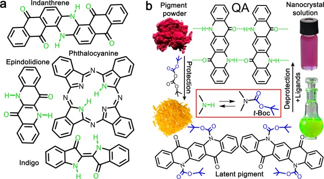
(a) Molecular structures of the pigments used in this work: indanthrene, epindolidione, phthalocyanine, indigo, and quinacridone (QA). (b) The protection–deprotection strategy employed in this work to synthesize colloidal pigment nanocrystals is shown for quinacridone, as an example. It starts from insoluble pigment powders, makes use of soluble latent pigments as precursors for the nanocrystal growth, and provides as a result colloidal nanocrystal dispersions.
All the pigments used in this work (Figure 1a) are commercially available materials, purchased from industrial sources at a cost of <$1/g. What all the molecules have in common is the presence of NH functional groups, which lead to strong intermolecular H-bonding and along with π–π stacking interactions are responsible for the low solubility/high stability of these materials (2H-phthalocyanine is a slight exception; here the NH groups only participate in intramolecular H-bonds, and π–π stacking interactions dominate crystallization). In contrast to dyes, organic pigments are highly resistant to being solubilized in organic or aqueous solvents.16 Therefore, Zambounis et al. (refs (16) and (17)) developed a method to convert insoluble microcrystalline hydrogen pigment powders into a soluble so-called “latent” pigment. This is obtained by attaching a protection group (t-butoxycarbonyl, t-Boc) to the N–H moieties of the pigments, which can be thermally cleaved off after homogeneous dissolution in the desired carrier medium (Figure 1b). This approach has been applied successfully for the coloration of plastics, especially foils used as color filters in LCD applications.17 Direct solution processing of t-Boc compounds has also been reported for organic thin-film electronics,7,18 however this approach has severe drawbacks because the crystallization of the final pigment film is hard to control and also depends strongly on the nature of the underlying substrate.19
It follows that obtaining high-quality crystals prior to deposition of films would be advantageous. Methods exist to obtain colloidal organic pigment crystals dispersions by methods like laser ablation20−22 or precipitation of a dilute solution in nonsolvents.23−25 These approaches lead to colloids with very low concentration of pigment materials. Moreover, surfactant-free nanoparticles are prone to aggregation. Overall such dispersions are not suitable for solution processing of device-quality thin films. Therefore, in this work, we have developed a novel synthesis route toward H-bonded pigment micro- and nanocrystals, which makes use of the ligand-mediated syntheses concepts known from the field of inorganic nanocrystals26−28 and combines them with latent pigment chemistry.16 The latent pigments, acting as highly soluble precursors, are crystallized in solution in the presence of ligand molecules by controlled removal of the t-Boc protection groups, achieved here in three ways: (i) simply by thermal cleavage,16,29 (ii) by an acid catalyzed reaction,30 and (iii) by a substitutional reaction with amines (Figures 1b and S1).31 From such syntheses, ligand-covered organic pigment micro- and nanocrystals of various shapes and sizes are obtained. The various colloidal crystals have a wide tunable range of absorption and photoluminescence (PL) from the visible to near-infrared range. We prepared example devices where the organic colloids are used in place of established inorganic colloidal semiconductors: phthalocyanine colloidal nanowire transistors are demonstrated with good on/off ratios and mobility, fabricated simply by drop casting of the colloidal solution on an untreated gate dielectric. Furthermore, quinacridone-based photodetectors are presented, deposited on paper substrates by paint-brushing. Their responsivity was significantly improved by attachment of an H-bonding, “smart” (strongly electron accepting) ligand. These examples demonstrate the versatility of the ligand-functionalized organic pigment nanocrystals synthesized here for applications in (opto)-electronics.
From Organic Pigments to Latent Pigments
The pigments were solubilized by attachment of t-Boc protection groups16 The t-butoxycarbonylation is performed by stirring the pigments in an organic solvent (for details see the Methods section) at room temperature together with di(t-butyl)-dicarbamate, using N,N′-dimethylaminopyridine as catalyst. An exception here is phthalocyanine, which is first lithiated to provide sufficient reactivity to di(t-butyl)-dicarbamate, replacing the necessity to apply any catalyst. The replacement of the H atoms of the NH groups by t-Boc removes the possibility of intermolecular H-bonding, which inhibits crystallization of the molecules to pigments, and thus eliminates any intermolecular coupling of electronic states. As a consequence, the absorption spectra of the latent pigments are hypsochromically shifted in respect to that of the initial parent pigments (Figure S2). Such a behavior has been reported before for instance for t-Boc protected quinizarin32 and quinacridone,18 and we observed it for all 5 pigments shown in Figure 2, where the latent pigment of quinacridone appears yellow, due to an absorption onset at 525 nm, whereas the pigment used as starting material exhibit colors from red to violet.33 With the exception of bis-t-Boc-indigo, all latent pigments exhibit also intense PL (Figure 2). Under illumination with an UV lamp the luminescence is observed by the bare eye in colors ranging between red, for t-Boc-phthalocyanine, and blue, observed for bis-t-Boc-epindolidione (Figure 2c). The absence of intense PL in the case of bis-t-Boc-indigo is not surprising, because for indigo a radiationless internal conversion process has been described to dominate over the radiative recombination, independent of the attachment of substitutions.34 Most important is, however, that protecting the insoluble parent pigments by t-Boc groups improves their solubility in organic solvents by approximately 5 orders of magnitude.16 This high solubility makes the latent pigments ideal precursors for the following syntheses of colloidal micro- and nanocrystals.
Figure 2.
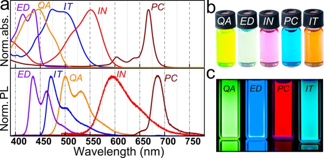
Optical properties of latent pigments. (a) Absorbance and luminescence spectra of all used latent pigment precursors. (b) Photo of the latent pigments as observed under ambient light due to scattering and (c) under ultraviolet illumination due to their PL (QA = quinacridone, ED = epindolidione, IN = indigo, PC = phthalocyanine, IT = indanthrene).
Nanocrystal Syntheses by Thermal Cleavage of the t-Boc Protection Groups
Heating is a convenient method used to remove the t-Boc protection groups from the latent pigments, as the t-Boc groups decompose irreversibly into gaseous CO2 and isobutene. Following t-Boc group decomposition, the deprotected pigment-forming molecules start to crystallize due to the strong intermolecular interactions, including H-bonding and π-stacking. Thus, the synthesis of organic pigment micro- and nanocrystals is reminiscent to the traditional “hot-injection” syntheses, which are extremely successful in the case of various inorganic nanocrystals.28,35−37 As in the case of inorganic nanocrystals, here also organic ligand molecules are added to the reaction mixtures to control nucleation and growth and to provide colloidal stability, solubility, and functionality to the final nanocrystals. As an example, quinacridone nanocrystals were synthesized in a mixture of oleic acid, used as coordinating solvent, and ligand molecules such as oleyl chloride or myristoyl chloride. After degassing and purification steps, the solution was heated to 280 °C under inert Ar-atmosphere, and a warm solution of bis-t-Boc-quinacridone dissolved in 1,2,4-trichlorobenzene was injected. After a growth time of 1 s the reaction flask was cooled to room temperature, and platelet shaped nanocrystals were collected after an appropriate washing step. These platelets are of submicron dimensions in lateral direction and have thicknesses in the order of 100 nm (Figures 3a and S3). Here the effect of the ligand attachment could be immediately observed, because such micronanocrystals can be dispersed in chloroform with concentrations up to 20 mg/mL, which is about 500 times higher concentration than was obtained so far in dispersions of quinacridone pigment micronanocrystals.20,24,38 An advantage of this hot-injection synthesis in comparison to the previous syntheses of quinacridone nanoparticles is also that temperature and growth time provide a convenient parameter to control the final nanocrystal properties. Increasing the injection temperature to 325 °C, for instance, results in increased nanocrystal sizes (Figure S4b), whereas, reducing the injection temperature to 150 °C and increasing the growth time provide rod-shaped nanocrystals, because of a changed reactivity of the oleoyl-myristoyl chloride and decomposition speed of bis-t-Boc-quinacridone(Figure S4c). This synthesis route is also very versatile, because changes of the ligand concentrations results in further uniform shapes (Figure S4d,e). Analogous recipes have been used here for the syntheses of ligand functionalized indigo-, indanthrene, and epindolidione micronanocrystals (Figure 3). Also in these cases by the growth conditions sizes and shapes of the nano/microcrystals can be controlled (differently sized and platelet shaped indigo nanocrystals are shown for instance in Figure S5). In all of these cases the final product we found to be superior to those obtained by the classical precipitation method,23 for which not only large size distributions are observed but also substantial admixtures of amorphous materials are found (see Figure S6).
Figure 3.
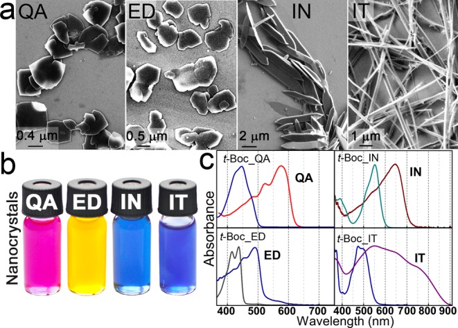
Organic pigment colloidal nanocrystals synthesized by thermal cleavage of the t-Boc protection groups from the latent pigment precursors. (a) Electron micrographs of the micronanocrystals on a Si substrate. (b) Photo of the colloidal dispersions. (c) Absorbance spectra of the latent pigment precursors and the resulting organic pigment micronanostructures. (QA = quinacridone, ED = epindolidione, IN = indigo, IT = indanthrene).
The solutions of the four different organic pigment nanocrystal species synthesized here by the hot injection approach exhibit various colors (Figure 3b), which are clearly changed with respect to those observed for the corresponding latent pigments. In all cases a significant red-shift between the absorbance features of the organic pigment micronanocrystals and the corresponding latent pigments was observed (Figure 3c), which is theoretically predicted to originate from the interplay between structural deformation, electrostatic potential, and intermolecular interaction.39 The balance between these three contributions is affected by the organic pigments crystal structure, enabling the adjustment of pigment colors by controlling their polymorphism. The concept of crystal engineering to achieve tunable pigmentary properties is highly developed in the pigment industry.40,41 In our approach, the color of quinacridone colloidal solutions can be tuned by the injection temperature, between red and violet. The brightest color shade is observed for sample QA I, synthesized at the lowest temperature, resulting in the α2-phase where the molecules form a criss-cross pattern,33 as is verified by synchrotron X-ray diffraction measurements (Figure 4). By the hot injection syntheses, darker colloidal solutions (QA II, QA III, Figure 4a) are obtained, and the onsets of their absorption spectra are red-shifted by up to 33 nm with respect to that of QA I. These samples are predominantly β-phase, where the molecules arrange in linear H-bonded chains,33 with small admixtures of α2-phase (Figure 4b).
Figure 4.
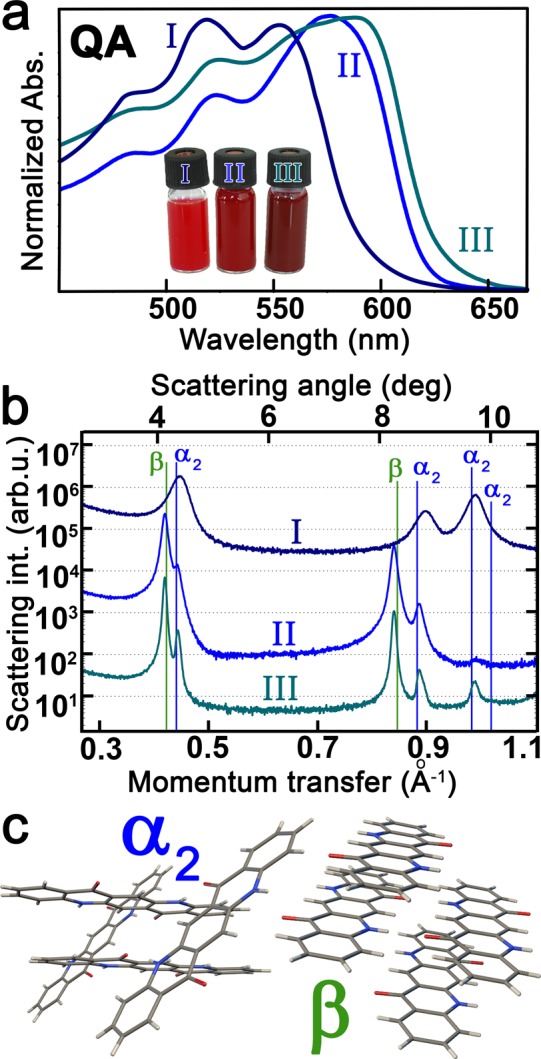
Controlling polymorphism in quinacridone micronanocrystals. (a) Absorbance spectra (b) and corresponding X-ray diffraction patterns for quinacridone micronanocrystal synthesized at various temperatures (QAI at 25 °C; QAII at 280 °C; QAIII at 340 °C). (c) Molecular arrangements of the observed α2 and β polymorphs, exhibiting a criss-cross H-bonding pattern and linear-chain H-bonding, respectively.
While the parent pigment powders used here as starting materials for the nanocrystal syntheses exhibit either weak or no luminescence, their conversion to colloidal nanocrystals improved their luminescence quantum yield by at least a factor of 10. Indeed, for all organic pigment nanocrystal species luminescence spectra can be measured, covering the visible and near-infrared spectral region up to 1300 nm (Figure 5a). The nanocrystal luminescence spectra also strongly differ from that of thin films fabricated by vacuum deposition as well as from the parent pigment powders or from nanomaterials prepared by the classical precipitation method. For quinacridone thin films, for instance, broadband spectra are observed, covering the wavelength region from 600 nm up to 800 nm,8 due to emission from dissociative states such as excimer and charge-transfer states.42 In contrast, the quinacridone nanocrystals exhibit a relatively narrow luminescence peak, with a line width (fwhm) of the excitonic transition fwhm = 44 nm and a Stokes shift SS = 33 nm (Figure 5b), which could be attributed to the rather monocrystalline and defect-free nature of the nanocrystals. This observed fwhm/SS ratio fits well to existing theoretical models, developed for high-quality semiconductor heterostructures,43 qualifying the quinacridone nanocrystals as a high-quality semiconducting material. By confocal micro-PL spectroscopy, performed on a single nanocrystal deposited on sapphire substrate, only a slightly smaller fwhm as those measured in the ensemble of a concentrated solution is measured (Figure S7), suggesting that all NCs in solution emit homogeneously at the same wavelengths.
Figure 5.
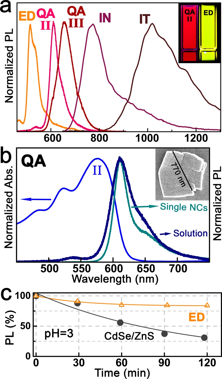
PL of organic pigment micronanocrystals. (a) Normalized PL spectra of various organic pigment micronanocrystals. The inset shows a photo of two cuvettes under ultraviolet illumination. (b) Absorbance and emission spectra of quinacridone nanocrystals in solution and of the single nanocrystal (NC) shown by the electron micrograph in the inset. (c) Stability test of an epindolidione nanocrystal film in acidic environment, compared to that of standard CdSe/ZnS core/shell nanocrystals.
An important consideration for eventual practical use of these materials, e.g., for applications at the interface to biochemistry or in epidermal electronics,44,45 is the stability of the organic nanocrystals in aqueous environments. Stability was tested for epindolidione nanocrystal films deposited on glass substrates, which were completely immersed in aqueous solutions with an acidic pH value, as an extreme model substance mimicking human sweat.46 In Figure 5c, a 12% decrease of the PL intensity within 120 min is shown. In comparison, a film of standard inorganic nanocrystals emitting at the same wavelength as epindolidione, namely CdSe/ZnS core/shell nanocrystals, exhibits a 6-fold larger drop of PL intensity within the same time span. Thus, the high optical quality of the fabricated organic pigment nanocrystals together with their superior stability holds strong promise for their exploitation in future photonic applications as a replacement to inorganic nanocrystals, which usually contain toxic heavy metals.
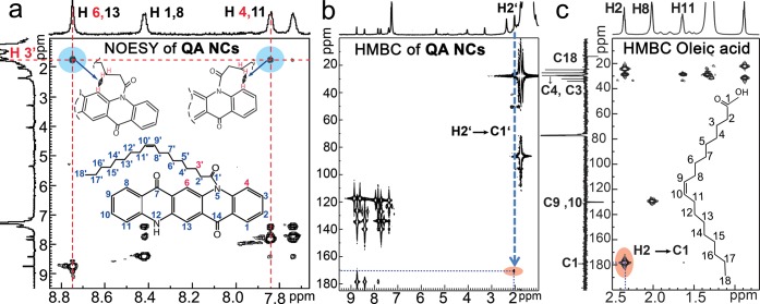
Of considerable interest is the mechanism of ligand attachment to the surfaces of the micronanocrystals. The high solubility of the quinacridone nanocrystals in chloroform can be quoted as an indirect proof for the attachment of ligand molecules on the nanocrystals surfaces. A direct proof for this attachment was obtained for the quinacridone nanoplatelets stabilized by oleyl chloride, shown in Figure 2a, by solution nuclear magnetic resonance (NMR) spectroscopy (Figures 6 and S8–S10). Due to the missing of appropriate reference spectra in literature, as a starting point of discussion first the NMR spectra of quinacridone molecules (solutions in DMSO) were studied. With the help of H,H and C,H correlation spectroscopy (Figures S8) all NMR peaks could be assigned to the corresponding atoms. On the basis of these assignments, also all peaks in the one-dimensional proton spectrum of quinacridone micronanocrystals covered by oleate ligands could be identified, for the aliphatic region (around 2 ppm) as well as for the aromatic part (around 8 ppm) of the quinacridone surface molecules (Figure S9). By nuclear Overhauser enhancement spectroscopy (NOESY, Figure 6a) homonuclear correlations are found between the protons 6 or 13 and 4 or 11 of the quinacridone molecules to the proton 3′ of the oleate ligands (sketch in Figure 6a). Additionally, in the two-dimensional heteronuclear multiple bond (HMBC) correlation map the correlation spot from proton H2′ at 2.1 ppm to the amide carbon C1′ at 170.5 ppm (Figure 6b) appeared to be shifted with respect to the corresponding spot measured for pure oleic acid (Figure 6c). Such a shift toward lower frequencies in both the C and the H NMR spectra indicates a direct bond between the carboxy group to the amine nitrogen (a similar shift is reported for the well-known system N,N′-ethylene-bis-oleamide, as is shown in Figure S10). Thus, both results, the NOESY and HMBC, evidence that the oleate headgroup (carbonyl atom C1′) is bound to the nitrogen atoms 5,11 on the quinacridone nanocrystals surfaces (as sketched in Figure 6a,b), which is a direct proof for the covalent attachment of ligands to the organic pigment micronanocrystal surfaces.
Figure 6.
Evidence for ligand attachment on the organic pigment nanocrystal surfaces. (a) Homonuclear H–H NOESY reveals correlations between protons of the quinacridone and the oleate ligands as evidence for ligand attachment. (b) HMBC map of quinacridone with oleate ligands and (c) of oleic acid exhibit shifted signatures for the H2–C1 bond. The numeration of the atoms is shown in the inset of (a).
Nanocrystal Syntheses by Acid Catalyzed Deprotection
While the thermal cleavage of the t-Boc protection groups to induce crystallization in a liquid matrix was successful for four out of the five species of H-bonded organic pigments studied in this work, phthalocyanine represents an exception. The bis-t-Boc-phthalocyanine shows the tendency to become deprotected and to crystallize already at room temperature. Mixing t-Boc-phthalocyanine kept after column chromatography in toluene/ethyl acetate (19:1) into acetone (1:1), for instance, results within 3 days in rectangular shaped microbars, whose mean dimensions can be roughly controlled by the concentration of the precursor in the solution (Figures S11a and 7a). These nanobars are luminescent (S11b), similarly as the micronanocrystals grown by thermal cleavage shown in Figure 3, however there are no ligands attached to the surfaces to obtain a stable colloidal solution. Therefore, for colloidal phthalocyanine we have developed a slightly changed synthetic protocol, which is based on a more controlled way to remove the t-Boc protection moieties from the latent pigment precursor as the self-deprotection observed when t-Boc-phthalocyanine is stored at room temperature.
Figure 7.
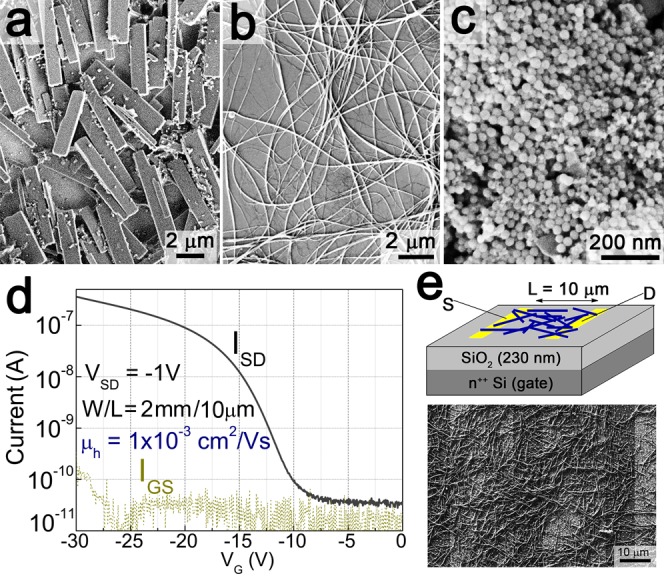
Phthalocyanine micronanocrystals (a) upon self-deprotection in the absence of any ligands, rectangular shaped microcrystals are obtained. When trifluoroacetic acid is used, dependent on the added ligand, (b) nanowires or (c) monodisperse nanospheres (with the addition of acetic anhydride) were achieved. (d) Transfer characteristics of a phthalocyanine nanowire transistor. (e) Schematic drawing of the FET structure, with an SEM image showing the drop-cast nanowires between the gold source–drain electrodes.
All pigment molecules used in this work contain two secondary amine groups which are t-Boc protected during their conversion into latent pigments. Besides thermal treatment, the most common methods to deprotect t-Boc-protected amines are to treat them either by a large quantity of an acid such as trifluoroacetic acid or by a relatively smaller quantity of a stronger mineral acid such as hydrochloric acid.30 By using trifluoroacetic acid, we were successful to obtain a controlled slow deprotection of the latent pigments and thus a kinetically controlled crystallization of the deprotected pigment molecules in solution. This attempt we applied to the t-Boc-phthalocyanine, which was treated in an acetone/toluene mixture with trifluoroacetic acid.47 The latter not only catalyzes the deprotection of the latent pigment but also its carboxylic groups might attach to the phthalocyanine nanomicrocrystal surfaces to provide the required ligands, for shape control and dispersibility improvement. As a result, after a growth time of 4 min, rather uniform phthalocyanine nanowires were obtained, with diameters in between 80 and 100 nm and lengths between 5 and 20 μm (Figure 7b). Similar nanowire shapes are often observed for phthalocyanines, even when they are crystallized by high-vacuum sublimation methods,48−52 due to the preferential stacking of the phthalocyanine molecules into their π–π direction ([001] direction of the monoclinic crystal). In comparison to the vacuum deposition methods, however, the chemical synthesis presented here offers an additional control of final micronanocrystal shape, by the choice and attachment of ligands. While the synthesis of phthalocyanine nanowires in trifluoroacetic acid appeared to be easily reproducible, by addition of a further ligand, namely acetic anhydride, completely different results were obtained. In the latter case, instead of the wire shape commonly found for phthalocyanines, spherical nanocrystals were obtained with a mean diameter of 38 nm and a narrow size distribution of ±10% (Figures 7c and S12).
In order to test the electrical transport in phthalocyanine nanocrystals, we fabricated field-effect transistor (FET) devices. The phthalocyanine micronanowires offer an obvious advantage over other nanocrystal shapes with respect to lateral charge transport. We were able to observe promising performance in FETs prepared by drop-casting of a phthalocyanine nanowire colloidal solution (Figure 7b). Highly doped Si was used as the gate electrode, with a 230 nm layer of SiO2 functioning as the gate dielectric. The nanowires were drop-cast from chloroform colloidal solution between two interdigitated gold electrodes with a 10 μm spacing, giving a FET structure as shown in Figure 7e. SEM examination of the drop cast films shows that the nanowires had a length of approximately 10–20 μm and width of tens of nanometers and formed a random network between the source and drain electrodes as shown in Figure 7e. Despite the disordered nature of the nanowires and inhomogeneous surface coverage, p-type field-effect current modulation was observed, with on/off ratios of 104, as shown in Figure 7d. The transfer characteristic as shown in this figure represents linear mode operation, which was found to be highly reversible over tens of cycles and 1 week of measurements. Application of source–drain voltages higher than 4 V was found to provide saturation behavior with currents in the microamp range, however this led to rapid breakdown of the device. This observation suggests that the current may be carried by only a limited amount of nanowires spanning the source and drain electrodes. This makes a determination of the intrinsic mobility of these nanowires difficult. Using a very conservative estimation assuming the full geometric width between electrodes to constitute an active channel (W = 2 mm) we calculate from the transconductance at linear regime a mobility of ∼1 × 10⁻³ cm2/(V s). In reality, the mobility could be significantly higher. The best results for vacuum-evaporated films of metal-free phthalocyanine are also in the 1 × 10⁻³ cm2/(V s) range, while the best results for other phthalocyanine derivatives rarely exceed the 0.1 cm2/(V s) range. The record mobility for this materials class is for titanyl phthalocyanine, with mobility >1 cm2/(V s).53,54 As is well-known from organic FET literature, bare SiO2 is considered a problematic dielectric layer giving inferior performance, due to surface states acting as traps and the hydrophilic surface leading to growth of small crystalline semiconductor domains. To overcome this, surface modification layers such as alkyl silanes are used to passivate traps and make the surface hydrophobic. We carried out a typical silanization procedure using n-octyl trimethoxysilane, according to published methods.55,56 We found no difference between treated and untreated samples in terms of transistor behavior. This suggests that since the crystals are already formed colloidally, with passivating ligands, before deposition, the semiconducting properties of the material are less sensitive to the dielectric surface properties. We found that other nanocrystal modifications of phthalocyanine (blocks, spheres, etc.) showed almost no measurable gate modulation, only the long nanowires showed promising FET performance. This represents an interesting potential approach to solution-processed organic FET devices.
Nanocrystal-Based Photodetection and Syntheses by Amine Induced t-Boc Deprotection
An important field of applications for semiconductor nanocrystals with band gap energies in the visible and near-infrared is their use for photon-harvesting in solar cells.57−59 For such applications it is necessary to optimize the photoconducting properties of these materials. From the H-bonded organic pigments reported here, quinacridone, phthalocyanines, and epindolidione, have been recognized to be of potential interest for applications in photovoltaics in literature.8,9,13,18,60−63 For quinacridone thin films, prepared by vacuum sublimation, for instance, photoconductivity spectra were measured by us, however, the maximum responsivity we obtained was smaller than 1 mA/W (Figure S13). For the solution-processed micronanocrystals, in contrast, better values were found, because they could be processed in the form of bulk-heterojunctions. For that purpose the micronanocrystals were mixed with an electron acceptor and transporter, the fullerene derivative phenyl-C61-butyric acid methyl ester (PCBM),64,65 known from conventional organic solar cells. The response of such a quinacridone nanocrystal/PCBM heterojunction, fabricated simply by drop casting of a blend with a 1/1 mass ratio on an interdigitated electrode structure with 20 μm spacing, reached up to 10 mA/W under a bias of 1 kV/cm (Figure S13). These values are on-par with those measured in the best binary blends of conjugated polymers and PCBM, which are used as photosensitive layers in state-of-the-art, solution-processed organic solar cells.66 We have obtained here substantial improvements by replacing the nanocrystal-electron acceptor blend in the photoconducting film by direct attachment of the electron accepting species as a ligand to the nanocrystal surface. As an electron-accepting moiety we chose riboflavin, better known as vitamin B2. The riboflavin molecule offers several sites for possible H-bonds to the surfaces of the pigment molecules and micronanocrystals. Riboflavin is known from biochemistry as an electron acceptor in various biochemical reaction pathways.67 We therefore decided to use riboflavin as a ligand with two roles: to bind to the crystallite surfaces via H-bonding and to provide a strong electron acceptor. First we tested the electron-accepting properties of soluble derivatives of riboflavin (riboflavin myristate and flavin mononucleotide, Figure S14a) with respect to the organic pigment nanocrystals. Evidence for photoinduced charge transfer was found in oleate ligand-covered quinacridone nanocrystals blended with riboflavin myristate. The observation of both luminescence quenching (Figure 8a) and a photoinduced electron resonance signal (Figure 8b) is a strong indication68 that photoinduced charge transfer occurs from the quinacridone crystal to the riboflavin moiety, as shown schematically in Figure 8c. The g-value of the photoinduced signal is 2.002 and is likely an overlay of contributions from the Flavin radical anion and the radical cation in quinacridone. Due to the very similar g-value of organic radicals, we could not discriminate between both signals. In addition to blends of quinacridone, both epindolidione and phthalocyanine also showed promising photoconductivity when mixed with flavine mononucleotide. In all cases, the photoconductivity spectra correspond to the absorbance spectra of the organic pigments (Figure S14b). All these experiments confirm that riboflavin is an appropriate molecule to act as electron acceptor to enhance photoconductivity of H-bonded organic pigment nanocrystals.
Figure 8.
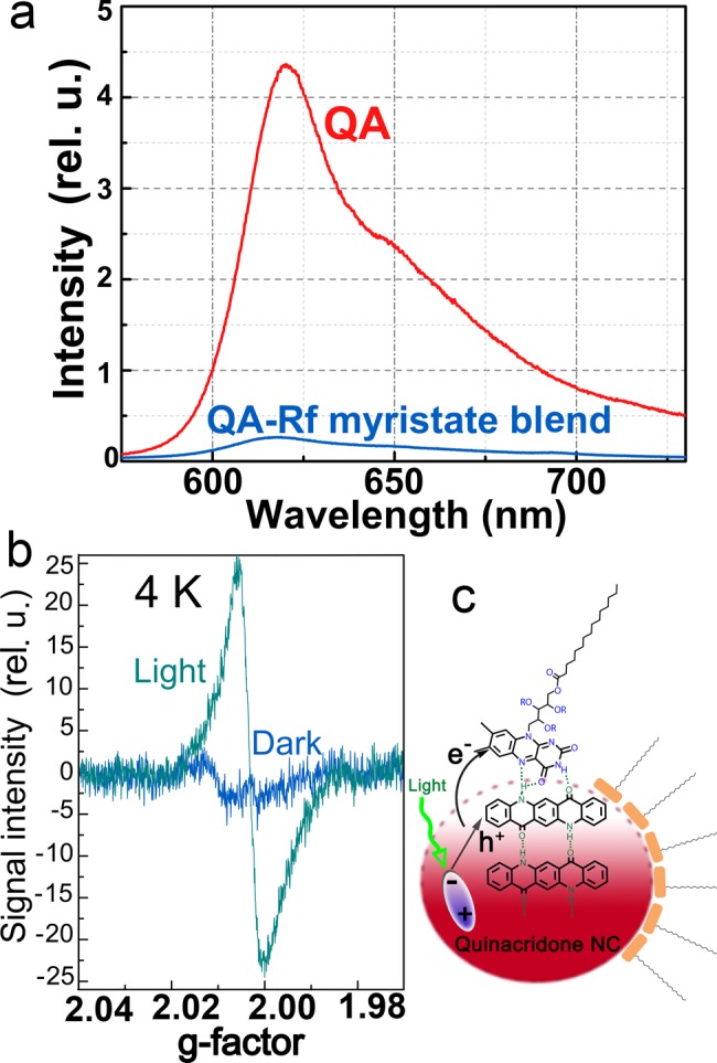
Evidence for charge transfer between quinacridone nanocrystals and riboflavin. (a) PL of a pure QA nanocrystal film and a QA-riboflavin myristate (Rf) blend. (b) Light-induced electron paramagnetic resonance of a blend containing quinacridone nanocrystals and Rf. The experiments in (a) and (b) evidence a light induced charge transfer. (c) Sketch of the electron-transfer process after photoexcitation of an electron–hole pair.
To synthesize organic pigment micronanocrystals coated by riboflavin based ligands from quinacridone, the two synthetic routes presented above are not suitable, because of the instability of the riboflavin at high temperatures and because of the solubility of quinacridone in strong acids. Thus, here we applied a third synthetic route, which is based on the ability of the t-Boc moiety to migrate between amine groups.31 Offering a primary amine in large excess with respect to the bis-t-Boc-quinacridone latent pigments results in their deprotection. In this synthesis, oleylamine was used as coordinating solvent and as deprotection reagent, functioning to accept t-Boc moieties migrating from the bis-t-Boc-quinacridone latent pigments. Under Ar atmosphere the latent pigment was injected in chloroform solution to an oleylamine mixture containing also riboflavin myristate. This synthesis was performed at a temperature of 45 °C, and after a growth time of 105 min the rod-shaped quinacredone nanocrystals shown in Figure 9 were collected. In contrast to the high-temperature syntheses of quinacridone, this synthesis provides a single crystalline phase (α2), which should be beneficial also for the optical properties of these nanocrystals.
Figure 9.
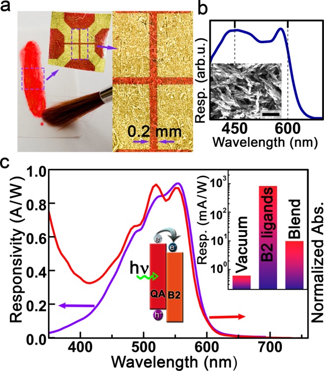
Photoconductivity in films of quinacridone micronanocrystals with riboflavin myristate ligands. (a) Device structure obtained by paint brushing on paper. (b) Photoresponsivity spectrum measured on the device shown in (a). The inset shows the used micronanocrystals (scale bar is 200 nm). (c) Absorbance and photoconductivity spectra of a device prepared on glass substrate. The inset compares the responsivity value obtained with the riboflavin (B2) ligands with those obtained by vacuum sublimation and in a hybrid blend with PCBM.
For demonstration of the high potential of these riboflavin coated nanocrystals first a very simple device architecture, applicable for “paper electronics”, was chosen.69 A photodetector was fabricated simply by painting of riboflavin (vitamin B2) functionalized quinacridone nanocrystals on paper, by using a paint brush, to obtain a homogeneous nanocrystal film. On top of this film, four gold contacts were sputtered through a shadow mask to obtain electrodes with a distance of 0.2 mm to each other. As shown in Figure 9a, the paper substrate and thus finally also the sample surface exhibited substantial roughness. Nevertheless, on this device a photoconductivity spectrum could easily be measured with good signal-to-noise ratio (Figure 9b). To determine the responsivity accurately, reference samples were fabricated on glass substrates. On the latter the absorbance spectrum was also measured, which perfectly fits to the photoconductivity spectrum, exhibiting a cutoff wavelength of 600 nm and a peak close to 550 nm (Figure 9c). The responsivity at its peak is surprisingly high, and the value of roughly 1 A/W corresponds to a product of external quantum efficiency times photoconductive gain of 190%, which is more than 1000 times better than that obtained from an evaporated solid film. The riboflavin-coated quinacridone device exhibits not only a high responsivity but also a high dark resistance of 100 GΩ, resulting (by assuming a Johnson noise-limited performance) in a high specific detectivity of 3 × 10¹³ Jones.
Conclusions
The demonstrated syntheses routes toward colloidal H-bonded organic pigment micronanocrystals via deprotection of latent pigment precursors can be applied to various materials and is likely not limited to the five archetypical organic pigments presented above. Depending on the stability of the latent pigment precursors and ligands in various media, three different deprotection routes have been applied to initialize controlled crystal growth in solution. While thermal deprotection via a hot-injection type of synthesis results within a few minutes growth time in nucleation and growth of micronanocrystals for the majority of pigments investigated here, for phthalocyanine altered protection and deprotection recipes have to be used. In this case, the deprotection catalyzed by an acid resulted either in uniform nanowires or in monodisperse nanospheres. In all cases the choice of ligands is of prime importance, because they provide not only the high solubility of the micronanocrystals in solutions but also regulate their shape and eventually provide additional functionality. Ligand attachment was directly proven by NMR spectroscopy for the case of oleylate on quinacridone. On the latter also functional, biological ligands were attached via H-bonding, which allowed demonstration of photoconductors with responsivities outperforming those of vacuum-deposited reference layers by more than 3 orders of magnitude. This demonstrates the great potential of the H-bonded organic micronanocrystals for applications in (opto-)electronics, which is of special interest also because of the low toxicity70 and low cost of the used materials as well as the simplicity of device fabrication. The latter is underlined by the phthalocyanine nanowire transistors, which were reproducibly fabricated simply by drop casting on prepatterned electrodes and reliably operated in all cases. Thus, the organic pigment micronanocrystals might pave the way toward a new generation of solution processed organic electronics, benefiting from the high robustness of these materials, their optical and semiconducting properties, and their facile preparation via the protection/deprotection route presented here.
Methods
Materials
The commercially available pigments were obtained from Kremer Pigmente or from TCI, whereas epindolidione was synthesized in-house. For this purpose we followed the synthetic approach reported by Jaffe and Matrick.71 Although the suggestions of Kemp et al.72 proposed for the preparation of the first three intermediates were taken into account. Before use, phthalocyanine was purified by temperature gradient high-vacuum sublimation due to a very large fraction of impurities in commercial samples. The other pigments were used as-received. All other chemicals were obtained from Sigma-Aldrich and used without additional purification.
Converting Pigments to Latent Pigments
N,N-Bis(tert-butyloxycarbonyl)-quinacridone (Bis-t-Boc-QA) and N,N-bis(tert-butyloxycarbonyl)-indigo (Bis-t-Boc-IN) were prepared by mixing quinacridone pigment powder (3.75 g, 12 mmol) or indigo pigment powder (3.114 g, 12 mmol) in anhydrous dichloromethane (CH2Cl2, 600 mL) kept under nitrogen atmosphere at room temperature with di-tert-butyl dicarbonate (t-Boc2O, 12.644 g, 58 mmol for quinacridone and 9.81 g, 45 mmol for IN) and 4-dimethylaminopyridine (DMAP, 2.93 g, 24 mmol). These mixtures were stirred for 48 h and monitored by thin layer chromatography (TLC). The crude solution was evaporated almost to dryness and filtrated in a chromatography column through a 80-fold amount of silica gel, with a 19/1 mixture of toluene/ethyl acetate (AcOEt) for quinacridone (9/1 was used for indigo) to obtain crystalline products in yields up to 90% for indigo and 56% for quinacridone. Before the synthesis of micronanocrystals the samples were recrystallized from AcOEt for further purification. N,N-bis(tert-butyloxycarbonyl)-epindolidione (Bis-t-Boc-ED) and (mono-t-Boc-ED) as well as mixtures of N,N-bis(tert-butyloxycarbonyl)-indanthrene (Bis-t-Boc-IDT) and mono-t-Boc-IDT were prepared in analogy to the two compounds above, however, in tetrahydrofuran (THF) as solvent instead of dichloromethane. In detail the following reaction parameters were applied: t-Boc-ED: the mixture contained 100 mg (0.38 mmol) epindolidione, 414 mg (1.95 mmol) t-Boc2O, 93 mg (0.76 mmol) DMAP, and 30 mL dry THF, stirring time was 52 h, filtration through 30 g silica gel with toluene/AcOEt (9:1) yielded 19% of bis-t-Boc-EP in the nonpolar fractions; mixture of mono- and bis-t-Boc-IDT: the mixture contained 270 mg (0.6 mmol) indanthrene, 1.33 g (6.1 mmol) t-BOC2O, 146 mg (1.2 mmol) DMAP, and 200 mL dry THF, stirring time was 96 h, filtration through 30 g silica gel with toluene/AcOEt (9:1) provided 180 mg of solid material. Solubilization of phthalocyanine required an additional step before the tert-butyloxycarbonylation could be performed. First, the free base PC was purified by temperature gradient sublimation in vacuum. The t-Boc-PC was then prepared in a cooled (−30 °C, methanol bath cooled with liquid nitrogen) suspension of 102 mg phthalocyanine (0.2 mmol) in 12 mL of dry THF, by adding 0.8 mL of a 2 M n-butyllithium cyclohexane solution, which was stirred for 30 min (at a temperature below −10 °C). After this step, 475 mg of t-Boc2O (2 mmol, 0.5 mL) were added and stirred for 20 h at a temperature below −10 °C, maintained by a Peltier element. TLC monitoring was performed. The final solution was filtrated through 30 g of silica gel with toluene/ethyl acetate (19:1). After filtration, the solution was used for nanocrystal synthesis.
Creation of Micronanocrystals from Latent Pigments
Quinacridone Micronanocrystals
In a typical hot injection synthesis of quinacredone with the shape of platelets, 10 mL of oleic acid was loaded into a three-neck flask and stirred under vacuum at 120 °C for 30 min. The solution was cooled down to room temperature and then 2.0 mL (27.6 mmol) of thionyl chloride was injected under stirring. Stirring was continued for 1 h at room temperature. Then the mixture was again heated to 120 °C under vacuum for 30 min and further stirring. This reaction mixture, or instead 4.0 mL (14.7 mmol) myristoyl chloride in 6.0 mL oleic acid was also used, was heated to 280 °C under vigorous stirring. A warm solution of 50 mg bis-t-Boc-QA in 2 mL of 1,2,4-trichlorobenzene was injected via syringe, and the reaction mixture was quickly cooled down, 1 s after injection, by changing the heating mantle to a water bath. Reducing the injection temperature to 150 °C and increasing the growth time to 2 min resulted in nanorods. Analogous recipes have been used for the syntheses of indigo and indanthrene micronanocrystals, however, at a reduced injection temperature of 240 °C. The synthesis of quinacredone nanocrystals with riboflavin ligands was required as a first step to prepare a soluble derivative of Riboflavin (Rf). For this purpose 10.4 g (74 mmol) of Rf was stirred with 10.2 g of anhydrous potassium carbonate in 200 mL of anhydrous THF. Under nitrogen atmosphere a solution of 5 mL (18.4 mmol) myristoyl chloride in 45 mL of anhydrous THF was dropwise added for 14–16 h. The vigorous stirring was continued for another 3 days. The whole solution was filtrated through diatomite, and the solvent was removed in vacuum. The dried product was redissolved in chloroform and rinsed 2 times with deionized water. After the chloroform was removed in vacuum the Rf-myristate was readily used for the synthesis of the quinacridone nanocrystals. In particular, 2.5 g of Rf-myristate was mixed with 5 mL vacuum-dried OLA, kept under argon atmosphere at 45 °C. 100 mg (0.195 mmol) of bis-t-Boc-QA dissolved in 1 mL warm chloroform was injected, and the growth was performed under vigorous stirring for 180 min. Equivalent results are also obtained by using a butylamine/toluene 1/1 mixture instead of OLA. In this case the growth temperature is decreased to room temperature, and the growth time is halved. In both cases the reaction was quenched by adding cyclohexane, and 6–8 washing steps were performed with chloroform/cyclohexane.
Epindolidione Micronanocrystals
For the synthesis of 30 mg of mono- and bis-t-Boc-ED was suspended in 2 mL of anhydrous quinoline under vigorous stirring. The mixture was heated with moderate rate to 210 °C. During heating a change of color was observed toward deep orange. Two min after the color change 0.4 mL myristoyl chloride was injected, and the solution was cooled down to room temperature.
Washing Procedures
After synthesis, the organic pigment micronanocrystals were isolated by adding cyclohexane in a volume ratio of 3:1 to the crude colloidal solutions, followed by centrifugation (relative centrifugal force = 14.100 g, 5 min) and redispersion in chloroform. The washing step was repeated four times before the micronanocrystals were stored in chloroform or in chlorobenzene.
Micronanocrystal Characterization
Electron microscopy images were taken with a JEOL JSM-6400 SEM microscope. Absorbance spectra were measured on nanocrystal films on glass substrates and from monomers and precursors in solution. The PL was measured in solution. Micro-PL was excited at 488 nm with at laser focused down with a microscope objective lens to a spot diameter of ∼1 μm. The PL signal was analyzed by a spectrometer with 0.75 m focal length and detected by a Si charge-coupled device. X-ray diffraction patterns were measured using synchrotron radiation at beamlines BM20/ESRF, Grenoble and powder diffraction beamline P02 at Hasylab Hamburg with 11.5 and 60 keV X-ray photons, respectively. Room temperature 1H and 13C solution NMR spectra were recorded on a Bruker Ascend 700 spectrometer operating at 700.33 MHz (1H) or at 176.1 MHz (13C). Chemical shifts are given in ppm relative to residual solvent (CHCl3, 7.27 ppm) for 1H and to a CDCl3 solution of TMS (0 ppm) as external standard for 13C. All 1H–{13C, 15N} cross-polarization magic angle spinning (CPMAS) spectra were recorded on a narrow-bore 11.7 T instrument (500 MHz, 1H Larmor frequency) with spinning rates of 10.0 kHz at 298 K.
Devices Fabrication and Characterization
All devices were fabricated and tested in ambient air. Interdigital electrodes were fabricated by thermal evaporation through a shadow mask or by applying first a photolithography step. The micronanocrystals were deposited on the electrodes by drop-casting from chloroform. Photoconductivity spectra were measured with an Acton SpectraPro 150 monochromator and a Signal Recover 7265 Lock-in amplifier. A pyrometer from Spectrum Detectors Inc. (STEP 49, calibrated by the National Institute of Standards and Technology (NIST)) was used to determine the illumination power.
Acknowledgments
We acknowledge financial support from the Austrian Science Fund FWF via the projects SFB IR-ON, TRP 294-N19, I-958-N20 and the Wittgenstein Prize for N.S.S. The authors thank C. Leitner from Keyence International NV/SA for the digital microscopy images and Armando Rastelli for support. NMR measurements were carried out at the Austro-Czech RERI-uasb NMR center which was established with financial support from the European Union through the EFRE INTERREG IV ETC-AT-CZ program (project M00146, “RERI-uasb”). D.K. acknowledges financial support from the Austrian Academy of Sciences (DOC-Fellowship).
Supporting Information Available
Supporting Figures S1–S13. This material is available free of charge via the Internet at http://pubs.acs.org.
Author Present Address
† Faculty of Science, University of South Bohemia, Branišovská 31, 370 05 České Budějovice.
Author Present Address
‡ Materials for Electronics and Energy Technology (i-MEET), Friedrich-Alexander Universität Erlangen-Nürnberg, Martensstraße 7, 91058 Erlangen, and Energie Campus Nürnberg (EnCN), Fürther Straße 250, 90429 Nürnberg, Germany
The authors declare no competing financial interest.
Supplementary Material
References
- Herbst W.; Hunger K.. General. In Industrial Organic Pigments, 3rd ed.; WILEY-VCH: Weinheim, 2004; pp 1–179. [Google Scholar]
- Głowacki E. D.; Voss G.; Sariciftci N. S. Adv. Mater. 2013, 25, 6783. [DOI] [PubMed] [Google Scholar]
- The annual production is reported in the Organization for Economic Cooperation and Development (OECD) Screening Information Data Set (SIDS), CAS no. 147-14-8.
- Shakhnovich A.; Belmont J.. Pigments for Inkjet Applications. The chemistry of Inkjet Inks; World Scientific Publishing Co.: Singapore, 2010; pp 101–122. [Google Scholar]
- Irimia-Vladu M.; Głowacki E. D.; Troshin P. A.; Schwabegger G.; Leonat L.; Susarova D. K.; Krystal O.; Ullah M.; Kanbur Y.; Bodea M. A.; Razumov V. F.; Sitter H.; Bauer S.; Sariciftci N. S. Adv. Mater. 2012, 24, 375–380. [DOI] [PubMed] [Google Scholar]
- Anokhin D. V.; Leshanskaya L. I.; Piryazev A. A.; Susarova D. K.; Dremova N. N.; Shcheglov E. V.; Ivanov D. A.; Razumova V. F.; Troshin P. A. Chem. Commun. 2014, 50, 7639–7641. [DOI] [PubMed] [Google Scholar]
- Yanagisawa H.; Mizuguchi J.; Aramaki S.; Sakai Y. Jpn. J. Appl. Phys. 2008, 47, 4728–4731. [Google Scholar]
- Głowacki E. D.; Leonat L.; Irimia-Vladu M.; Schwödiauer R.; Ullah M.; Sitter H.; Bauer S.; Sariciftci N. S. Appl. Phys. Lett. 2012, 101, 023305. [Google Scholar]
- Głowacki E. D.; Irimia-Vladu M.; Kaltenbrunner M.; Gasiorowski J.; White M. S.; Monkowius U.; Romanazzi G.; Suranna G. P.; Mastrorilli P.; Sekitani T.; Bauer S.; Someya T.; Torsi L.; Sariciftci N. S. Adv. Mater. 2013, 25, 1563–1569. [DOI] [PubMed] [Google Scholar]
- Gregory P. J. Porphyrins Phthalocyanines 2000, 4, 432–437. [Google Scholar]
- Law K. Y. Chem. Rev. 1993, 93, 449–486. [Google Scholar]
- Grätzel M. J. Photochem. Photobiol., A 2004, 164, 3–14. [Google Scholar]
- Hardin B. E.; Hoke E. T.; Armstrong P. B.; Yum J. H.; Comte P.; Torres T.; Frechet J. M. J.; Nazeeruddin M. K.; Grätzel M.; McGehee M. D. Nat. Photonics 2009, 3, 406–411. [Google Scholar]
- For a review see:Dimitrakopoulos C. D.; Malenfant P. R. L. Adv. Mater. 2002, 14, 99–117. [Google Scholar]
- Bao Z.; Lovinger A. J.; Dodabalapur A. Appl. Phys. Lett. 1996, 69, 3066–3068. [Google Scholar]
- Zambounis J. S.; Hao Z.; Iqbal A. Nature 1997, 388, 131–132. [Google Scholar]
- Schaedeli U.; Zambounis J. S. Iqbal A.; Hao Z.; Dubas H.; 1993, EP 0654711.
- Chen T. L.; Chen J. J-A.; Catane L.; Ma B. Org. Electron. 2011, 12, 1126–1131. [Google Scholar]
- Głowacki E. D.; Voss G.; Demirak K.; Havlicek M.; Sünger N.; Okur A. C.; Monkowius U.; Gasiorowski J.; Leonat L.; Sariciftci N. S. Chem. Commun. 2013, 49, 6063–6065. [DOI] [PubMed] [Google Scholar]
- Sugiyama T.; Asahi T.; Takeuchi H.; Masuhara H. Jpn. J. Appl. Phys. 2006, 45, 384–388. [Google Scholar]
- Asahi T.; Sugiyama T.; Masuhara H. Acc. Chem. Res. 2008, 41, 1790–1798. [DOI] [PubMed] [Google Scholar]
- Tamaki Y.; Asahi T.; Masuhara H. J. Phys. Chem. A 2002, 106, 2135–2139. [Google Scholar]
- Haberkorn H.; Franke D.; Frechen Th.; Goesele W.; Rieger J. J. Colloid Interface Sci. 2003, 259, 112–126. [DOI] [PubMed] [Google Scholar]
- Wang J.; Zhao Y.; Zhang J.; Zhang J.; Yang B.; Wang Y.; Zhang D.; You H.; Ma D. J. Phys. Chem. C 2007, 111, 9177–9183. [Google Scholar]
- Nitschke C.; O’Flaherty S. M.; Kroell M.; Blau W. J. J. Phys. Chem. B 2004, 108, 1287–1295. [Google Scholar]
- Yu W. W.; Wang Y. A.; Peng X. Chem. Mater. 2003, 15, 4300–4308. [Google Scholar]
- van Embden J.; Mulvaney P. Langmuir 2005, 21, 10226–10233. [DOI] [PubMed] [Google Scholar]
- Murray C. B.; Noms D. J.; Bawendi M. G. J. Am. Chem. Soc. 1993, 115, 8706–8715. [Google Scholar]
- Rawal V. H.; Cava M. P. Tetrahedron Lett. 1985, 26, 6141–6142. [Google Scholar]
- Ashworth I. W.; Cox B. G.; Meyrick B. J. Org. Chem. 2010, 75, 8117–8125. [DOI] [PubMed] [Google Scholar]
- Ouchi H.; Saito Y.; Yamamoto Y.; Takahata H. Org. Lett. 2002, 4, 585–587. [DOI] [PubMed] [Google Scholar]
- Kim J. M.; Kang J. H.; Han D. K.; Lee C. W.; Ahn K. D. Chem. Mater. 1998, 10, 2332–2334. [Google Scholar]
- Paulus E. F.; Leusen F. J. J.; Schmidt M. U. CrystEngComm 2007, 9, 131–143. [Google Scholar]
- de Melo J. S. S.; Rondao R.; Burrows H. D.; de Melo M.; Navaratnam S.; Edge R.; Voss G. ChemPhysChem 2006, 7, 2303–2311. [DOI] [PubMed] [Google Scholar]
- Talapin D. V.; Rogach A. L.; Kornowski A.; Haase M.; Weller H. Nano Lett. 2001, 1, 207–211. [DOI] [PubMed] [Google Scholar]
- de Mello Donegá C.; Liljeroth P.; Vanmaekelbergh D. Small 2005, 1, 1152–1162. [DOI] [PubMed] [Google Scholar]
- Dabbousi B. O.; Rodriguez-Viejo J.; Mikulec F. V.; Heine J. R.; Mattoussi H.; Ober R.; Jensen K. F.; Bawendi M. G. J. Phys. Chem. B 1997, 101, 9463–9475. [Google Scholar]
- Wang C.; Chen D.; Chen W.; Chen S.; Ye K.; Zhang H.; Zhang J.; Wang Y. J. Mater. Chem. C 2013, 1, 5548–5556. [Google Scholar]
- Fukunaga H.; Fedorov D. G.; Chiba M.; Nii K.; Kitaura K. J. Phys. Chem. A 2008, 112, 10887–10894. [DOI] [PubMed] [Google Scholar]
- Erk P.; Hengelsberg H.; Haddow M. F.; van Gelder R. CrystEngComm 2004, 6, 474–483. [Google Scholar]
- Desiraju G. R. J. Mol. Struct. 2003, 656, 5–15. [Google Scholar]
- Rossi L.; Bongiovanni G.; Lanzani G.; Mura A.; Borghesi A.; Tubino R.; Kalinowski J. Adv. Mater. Opt. Electron. 1997, 7, 35–38. [Google Scholar]
- Yang F.; Wilkinson M.; Austin E. J.; ÓDonnell K. P. Phys. Rev. Lett. 1993, 70, 323–326. [DOI] [PubMed] [Google Scholar]
- Kim D. H.; Lu N.; Ma R.; Kim Y. S.; Kim R. H.; Wang S.; Wu J.; Won S. M.; Tao H.; Islam A.; Yu K. J.; Kim T.; Chowdhury R.; Ying M.; Xu L.; Li M.; Chung H. J.; Keum H.; McCormick M.; Liu P.; Zhang Y. W.; Omenetto F. G.; Huang Y.; Coleman T.; Rogers J. A. Science 2011, 333, 838–843. [DOI] [PubMed] [Google Scholar]
- Hammock M. L.; Chortos A.; Tee B. C. K.; Tok J. B. H.; Bao Z. Adv. Mater. 2013, 25, 5997–6038. [DOI] [PubMed] [Google Scholar]
- Matousek J. L.; Campbell K. L. Vet. Dermatol. 2002, 13, 293–300. [DOI] [PubMed] [Google Scholar]
- Honda T.; Kojima T.; Kobayashi N.; Fukuzumi S. Angew. Chem., Int. Ed. 2011, 50, 2725–2728. [DOI] [PubMed] [Google Scholar]
- Krauss T. N.; Barrena E.; Lohmüller T.; Spatz J. P.; Dosch H. Phys. Chem. Chem. Phys. 2011, 13, 5940–5944. [DOI] [PubMed] [Google Scholar]
- Tong W. Y.; Djurišić A. B.; Xie M. H.; Ng A. C. M.; Cheung K. Y.; Chan W. K.; Leung Y. H.; Lin H. W.; Gwo S. J. Phys. Chem. B 2006, 110, 17406–17413. [DOI] [PubMed] [Google Scholar]
- Wang F. X.; Liu Y. D.; Pan G. B. Mater. Lett. 2011, 65, 933–936. [Google Scholar]
- Tong W. Y.; Djurišić A. B.; Ng A. M. C.; Chan W. K. Thin Solid Films 2007, 515, 5270–5274. [Google Scholar]
- Xiao K.; Li R.; Tao J.; Payzant E. A.; Ivanov I. N.; Puretzky A. A.; Hu W.; Geohegan D. B. Adv. Funct. Mater. 2009, 19, 3776–3780. [Google Scholar]
- Pron A.; Garys P.; Zagorska M.; Djurado D.; Demadrille R. Chem. Soc. Rev. 2010, 39, 2577–2632. [DOI] [PubMed] [Google Scholar]
- Dong H.; Fu X.; Liu J.; Wang Z.; Hu W. Adv. Mater. 2014, 25, 6158–6183. [DOI] [PubMed] [Google Scholar]
- Klauk H. Chem. Soc. Rev. 2010, 39, 2643–2666. [DOI] [PubMed] [Google Scholar]
- Ito Y.; Virkar A. A.; Mannsfeld S.; Oh J. H.; Toney M.; Locklin J.; Bao Z. J. Am. Chem. Soc. 2009, 131, 9396–9404. [DOI] [PubMed] [Google Scholar]
- Gur I.; Fromer N. A.; Geier M. L.; Alivisatos A. P. Science 2005, 310, 462–465. [DOI] [PubMed] [Google Scholar]
- Kamat P. V. J. Phys. Chem. C 2008, 112, 18737–18753. [Google Scholar]
- Robel I.; Subramanian V.; Kuno M.; Kamat P. V. J. Am. Chem. Soc. 2006, 128, 2385–2393. [DOI] [PubMed] [Google Scholar]
- Walter M. G.; Rudine A. B.; Wamser C. C. J. Porphyrins Phthalocyanines 2010, 14, 759–792. [Google Scholar]
- Tomida M.; Kusabayashi S.; Yokoyama M. Chem. Lett. 1985, 8, 1305–1308. [Google Scholar]
- Chen J. J.; Chen T. L.; Kim B.; Poulsen D. A.; Mynar J. L.; Fréchet J. M.; Ma B. ACS Appl. Mater. Interfaces 2010, 2, 2679–86. [DOI] [PubMed] [Google Scholar]
- Varotto A.; Nam C. Y.; Radivojevic I.; Tomé J. P. C.; Cavaleiro J. A. S.; Black C. T.; Drain C. M. J. Am. Chem. Soc. 2010, 132, 2552–2554. [DOI] [PMC free article] [PubMed] [Google Scholar]
- Scharber M. C.; Mühlbacher D.; Koppe M.; Denk P.; Waldauf C.; Heeger A. J.; Brabec C. J. Adv. Mater. 2006, 18, 789–794. [Google Scholar]
- Heeger A. J. Adv. Mater. 2014, 26, 10–28. [DOI] [PubMed] [Google Scholar]
- Soci C.; Hwang I. W.; Moses D.; Zhu Z.; Waller D.; Gaudiana R.; Brabec C. J.; Heeger A. J. Adv. Funct. Mater. 2007, 17, 632–636. [Google Scholar]
- Blankenship R. E.; Molecular Mechanism of Photosynthesis, 2nd ed.; Wiley Blackwell: Chichester, 2014; pp111–131. [Google Scholar]
- Sariciftci N. S.; Smilowitz L.; Heeger A. J.; Wudl F. Science 1992, 258, 1474–1476. [DOI] [PubMed] [Google Scholar]
- Eder F.; Klauk H.; Halik M.; Zschieschang U.; Schmid G.; Dehm C. Appl. Phys. Lett. 2004, 84, 2673–2675. [Google Scholar]
- Hunger K. Rev. Prog. Color. 2005, 35, 76–89. [Google Scholar]
- Jaffe E. E.; Matrick H. J. Org. Chem. 1968, 83, 4004–4010. [Google Scholar]
- Kemp D. S.; Bowen B. R.; Muendel C. C. J. Org. Chem. 1990, 55, 4650–4657. [Google Scholar]
Associated Data
This section collects any data citations, data availability statements, or supplementary materials included in this article.


