Abstract
Optical resolution photoacoustic microscopy (OR-PAM), while providing high lateral resolution, has been limited by its relatively poor acoustically determined axial resolution. Although this limitation has been tackled in recent works by using either broadband acoustic detection or nonlinear photoacoustic effects, a flexible solution with three dimensional optical resolution in reflection mode remains desired. Herein we present a multi-view OR-PAM technique. By imaging the sample from multiple view angles and reconstructing the data using a multi-view deconvolution method, we have experimentally demonstrated an isotropic optical resolution in three dimensions.
1. Introduction
Small and quasi-transparent model organisms, such as zebrafish and Drosophila embryos, are widely used in developmental biology [1] and neurophysiology [2]. Due to their significance, many efforts have been recently made in imaging these small model animals with photoacoustic microscopy [3,4]. Optical resolution photoacoustic microscopy (OR-PAM) provides high-resolution images of biological samples with various endogenous or exogenous contrasts [5–7]. Although the high lateral resolution and label-free imaging capability makes OR-PAM an appealing choice, its relatively poor axial resolution has limited its applications.
Conventional OR-PAM systems achieve optical resolution by focusing light within the acoustic focal zone, providing down to submicron level lateral resolution [8]. However, optical focusing cannot provide adequate axial resolution in most practical cases [9]. OR-PAM relies on time-of-flight detection of acoustic signals to provide axial resolution. The acoustically determined axial resolution is limited by the bandwidth of the acoustic detection, and the typical value is usually around tens of microns [10], an order of magnitude worse than the lateral resolution. Many works have focused on enhancing the axial resolution of OR-PAM. Improved acoustic temporal resolution has been reported through the use of broadband detectors, such as high-frequency transducers [10] and optical ultrasound detectors [11]. However, these methods require custom designed hardware, and suffer from the severe attenuation of high frequency ultrasonic waves in biological tissue and coupling media, limiting the imaging depth and the working distance. Meanwhile, optical sectioning has been achieved in OR-PAM through photoacoustic nonlinearity [12,13]. However, in these optically-sectioned PAM techniques, because depth scanning is required to acquire A-line signals, the imaging speed is reduced.
In this article, we propose to improve resolution isotropy and to provide optical resolution in three dimensions (3D) by imaging the sample from multiple view angles and numerically integrating the information acquired from each angle. Multi-view deconvolution has been proven effective in other optical imaging modalities, particularly in light-sheet fluorescence microscopy (LSFM) [14,15]. By introducing the multi-view imaging approach into OR-PAM, we developed multi-view optical resolution photoacoustic microscopy (MV-OR-PAM) and have achieved optical-diffraction-limited resolution in 3D.
2. Theory and simulation
In a conventional OR-PAM system, a 3D image of an object is blurred by the effects of both diffraction-limited optical focusing and bandwidth limited acoustic detection. Here the effect of acoustic focusing in the lateral direction is negligible due to the fact that the dimension of the acoustic focal spot of a typical focused transducer is usually much larger than that of the optical focal spot. Additionally, along the axial direction within the acoustic focal zone, the acoustic detection in OR-PAM is linear and shift-invariant [10]. Mathematically, denoting f(r,z) as the object function we want to image, go(r,z) as the optical fluence distribution, ga(r,z) as the impulse response of the transducer, and I(r,z) as the final 3D image in acoustic pressure before taking the envelopes of the received photoacoustic signals, the image formation can be described as
| (1) |
Here, r is a vector representing two dimensional (2D) coordinates (x, y), z is the coordinate along the axial direction, *r denotes 2D convolution in the lateral directions, and *z denotes convolution along the z direction. Assuming the optical fluence along the axial direction within the optical depth of focus is uniform, the concatenating convolutions in the lateral and axial directions become a 3D convolution,
| (2) |
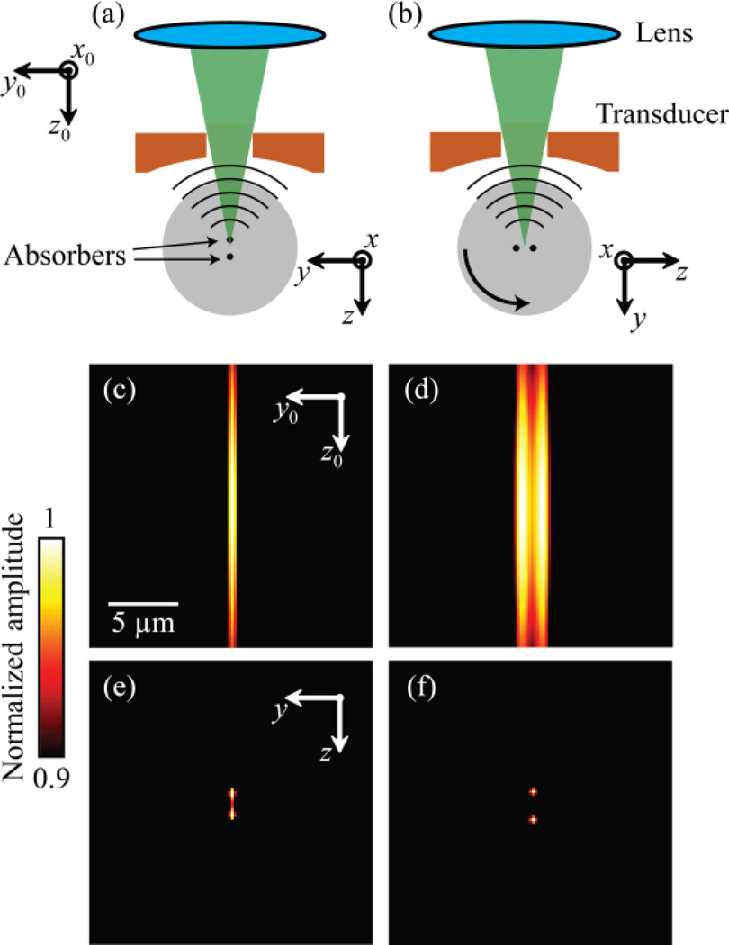
where g(r,z) is the overall 3D point spread function (PSF) of the system and g(r,z)=go(r,z=zf)·ga(z). Here zf is the depth of the focal plane. In a conventional OR-PAM system, the lab coordinate system is identical to the local coordinate system attached to the sample. In MV-OR-PAM, a sequence of low-axial-resolution 3D images is acquired at different view angles by rotating the sample as illustrated in Fig. 1 (a) and (b). In the local coordinate system attached to the sample, the acoustically-defined, low-resolution axis varies with the view angle. Therefore, the 3D image in each view is blurred by a local-coordinate PSF transformed from the original global-coordinate PSF, g(r,z). Hereafter, we denote (r,z) as the coordinates in the local system and (r0,z0) as the coordinates in the lab system. Provided that the transforms from the lab coordinate system at each view v to the local coordinate system, Tv, and the original untransformed PSF, g(r,z), are known a priori, a multi-view imaging problem can be formulated as
| (3) |
Fig. 1.
Principle and simulation of MV-OR-PAM. (a) Imaging two closely located (2 µm apart) point absorbers at angle 0° when the lab coordinate system is identical to the sample’s local coordinate system. (b) Rotate the sample by 90° and image it again. Notice the orientation of the absorbers and the local system are changed. (c, d) Acquired images from (a) and (b) under the global coordinate system. (e) Reconstructed image using MV-OR-PAM under the local coordinate system. (f) Ground truth image (blurred for display) of the two absorbers.
Here, Iv(r,z) is the measurement at view v. The underlying object function f(r,z) can be recovered with multi-view deconvolution methods. The multi-view extension of the Lucy-Richardson algorithm is chosen for its simplicity and performance demonstrated in other optical imaging modalities [16,17].
We simulated the principle of MV-OR-PAM, with the results shown in Fig. 1. Two point targets were placed 2 µm apart along the z axis and imaged at angle 0° [Fig. 1 (a)]. The entire object was then rotated 90° around the x axis and imaged again [Fig. 1 (b)]. At each view angle, the object was first convolved in the x, y directions with a 3D Gaussian illumination function that has full widths at half maxima (FWHM) of 2.0×2.0×57.0 µm3. The resultant 3D volume was then convolved with a typical ultrasound transducer’s impulse response, which is a Gaussian derivative function in the z direction, with a FWHM of 50.0 µm. We then took the envelope on each A-line to form single-view images at angle 0° [Fig. 1 (c)] and angle 90° [Fig. 1 (d)]. The final reconstructed image [Fig. 1 (e)] was calculated by applying the independent multi-view Lucy-Richardson algorithm [15] on these two volumes over 15 iterations. Compared to the ground truth image [Fig. 1 (f)], the signals from the two point sources originally mixed together in the upright view become resolvable in the reconstructed image. This indicates that MV-OR-PAM is able to recover the information missing in one view by integrating information from another view. Although envelope extraction, strictly speaking, violates the linearity of deconvolution, our analysis revealed that it is still a good approximation when measurements from multiple view angles are used and the PSF is much wider along the depth direction than the lateral directions (see Appendix).
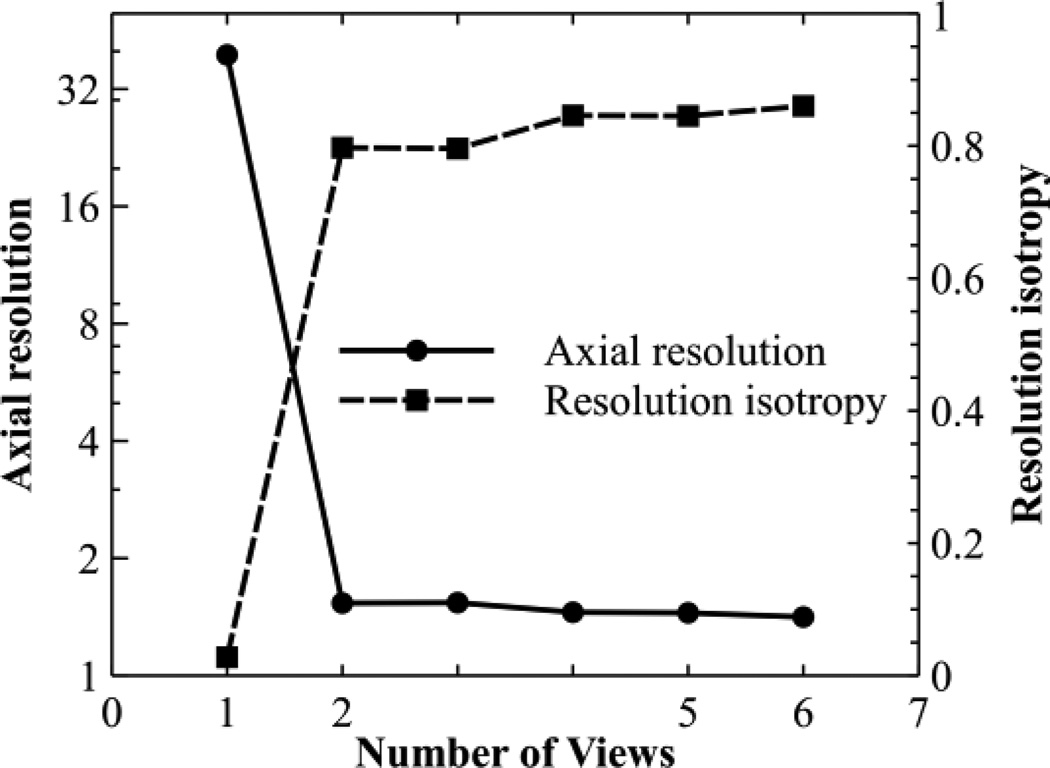
We also studied the effect of the number of views on the improvement of axial resolution and resolution isotropy through simulation. Different numbers of views were equally spaced within a 180° range. A point target located on the focal plane was imaged. The reconstructed B-scans were fitted to a 2D elliptical Gaussian function. The FWHM of the major and minor axes were measured as resolution values. The resolution isotropy was quantified as the ratio between the resolution values along the minor axis and major axis. The results are shown in Fig. 2. Both axial resolution and resolution isotropy are significantly improved when the first additional view is added, but further increases in the number of views result in diminished advantage. In a practical situation, however, the inclusion of more views will increase the overall signal to noise ratio (SNR) at the expense of data acquisition speed.
Fig. 2.
Simulating the effect of number of views on axial resolution and resolution isotropy. Views were spaced evenly within a 180° angle. Notice the left y axis is log scaled.
3. Experimental setup and methods
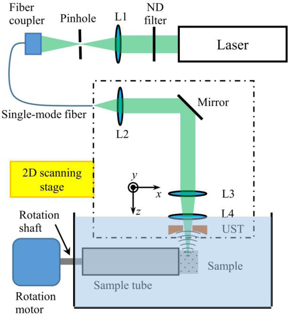
In order to experimentally validate MV-OR-PAM, we constructed an OR-PAM system with a subsystem that can rotate the sample during imaging. The original OR-PAM system has been detailed in [18]. Briefly, the system (Fig. 3) employs a 532-nm pulsed laser (SPOT-10-200-532, Elforlight). After attenuation by a variable neutral density filter, the laser beam was focused by a lens with a focal length of 200.0 mm. The focused light is spatially filtered by a 50-µm-diameter pinhole (P50C, Thorlabs) and coupled into a single-mode optical fiber through a fiber coupler. The fiber output is collimated by a doublet (F.L. = 25.0 mm, AC127-025-A, Thorlabs) and then focused by another identical doublet. A compensation lens (F.L. = 100.0 mm, LA1207-A, Thorlabs) corrects for water immersion, and a ring transducer (35 MHz center frequency, 25 MHz bandwidth) detects PA signals. The lateral resolution of the system is limited by the effective numerical aperture of the optical system and has been experimentally quantified as 2.6 µm [18].
Fig. 3.
Schematic of the MV-OR-PAM system. L1, condenser lens; L2, fiber collimator lens; L3, objective lens; L4, compensation lens; UST, ultrasound transducer. Both optical and acoustic axes are along the z direction under the lab coordinate system, and the rotation axis is along the x direction of the lab coordinate system.
Prior to imaging, the object to be imaged was immobilized in 3% agar gel and mounted in a sample holding tube. As shown in Fig. 3 the tube is connected to a rotating shaft driven by a stepper motor. The shaft passes through a spring-loaded PTFE seal (13125K68, McMaster-Carr) to ensure water-tightness and is supported by several bearings. A 2D raster scan along the x and y directions was performed at each view angle. Then, the sample was rotated by a preset angle around the x axis and scanned again. Each 2D scan generated a 3D data set with an optical-diffraction-limited lateral resolution and an acoustic-bandwidth-determined axial resolution.
Before reconstruction, we co-registered the 3D data sets acquired from different view angles to the local coordinate system of the sample. Sub-resolution absorbing beads (silanized iron oxide beads, 2 µm average diameter, Thermo Scientific) were uniformly mixed in agar as registration markers. The beads were segmented and localized using an algorithm modified from that described in [19], and the parameters were optimized empirically by matching the number of segmented beads per unit volume with the expected number concentration of the suspension. To ensure reliable segmentation, high frequency noises in the images were suppressed with a 2D Gaussian filter with an isotropic standard deviation of 2.55 µm along the lateral directions. The beads were then segmented using a difference-of-Gaussians filter with standard deviations of 6.25 µm and 7.38 µm. Local minima in the 3.75×3.75×3.75 µm3 neighborhood were considered as beads, and their positions were extracted by fitting a 3D quadratic function to this neighborhood in the original 3D image. The bead locations were then processed to generate a 3D affine transform from each view to the first view. After successful co-registration, the reconstruction was performed using an independent multi-view Lucy-Richardson algorithm [15]. Bead images with a lateral FWHM close to 2.6 µm (the experimentally quantified resolution value) were considered as good estimations of the 3D PSF of the system and were normalized and averaged to be the PSF used in the reconstruction algorithm. Furthermore, we applied Tikhonov regularization (regularization parameter = 0.006) to account for noises in the images [20].
4. Results and discussion
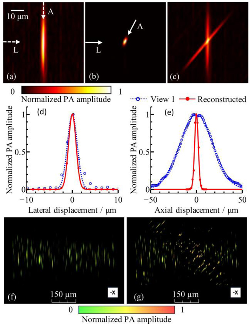
We imaged the sub-resolution beads to quantify the improvement of resolution isotropy in MV-OR-PAM. 3D images were acquired at two views 50° apart, then co-registered and reconstructed with 15 iterations. The B-scan images of a single bead from conventional, single-view OR-PAM and MV-OR-PAM are shown in Fig. 4 (a) and (b). Fig. 4 (c) shows the overlap of the two views. In Fig. 4 (d) and (e) the data points extracted from (a) and (b) were fitted with normalized Gaussian functions. We then quantified resolutions based on the FWHM of these Gaussian functions. The lateral resolutions of the single view image and reconstructed image were estimated as 2.6 µm and 2.0 µm, respectively. This slight improvement in lateral resolution is due to the deconvolution of the reconstruction algorithm. The axial resolutions, defined along the worst-resolution axis, were 42.2 µm and 4.7 µm for the single view image and reconstructed image, respectively. Thus we achieved a 9-fold improvement in axial resolution. Resolution isotropy, quantified as the ratio between the best-axis resolution and worst-axis resolution, was improved by a factor of 7 (from 0.060 to 0.41). Fig. 4 (f), (g) and Media 1 show volumetric renderings of both the single-view OR-PAM image and the image acquired by MV-OR-PAM.
Fig. 4.
Quantification of improvement of axial resolution and resolution isotropy. Image slices perpendicular to rotation axis (original B-scan plane) from (a) single view and (b) reconstructed 3D volume data. (c) Arithmetic fusion of the two views at the same area as (a) and (b), showing overlap between the two views. (d) Lateral line profiles from single view and reconstructed volume, indicated by the horizontal arrows marked as “L” in panels (a) and (b). (e) Axial line profiles extracted along the depth direction from single view image (a) and along the worst-resolution direction from the reconstructed image (b), both marked as “A”. (f), (g) Volumetric rendering of single-view dataset and reconstructed dataset. See Media 1 for a full view angle rendering of these two data sets.
To further validate MV-OR-PAM in biological imaging applications, we imaged a wild-type zebrafish embryo 6 days post-fertilization (dpf) ex vivo. Zebrafish husbandry was described in our previous work [21]. All animal work was performed in compliance with Washington University’s institutional animal protocols. Before imaging, the embryo was anaesthetized with tricaine and fixed with 4% paraformaldehyde (PFA) and 1X phosphate buffered saline (PBS). Two images were acquired with angles approximately 90° apart, with a field-of-view (FOV) of 0.5 mm by 3.0 mm and a step size of 2.5 µm for both x and y directions. The sample was rotated with respect to the x axis in the local coordinate system.
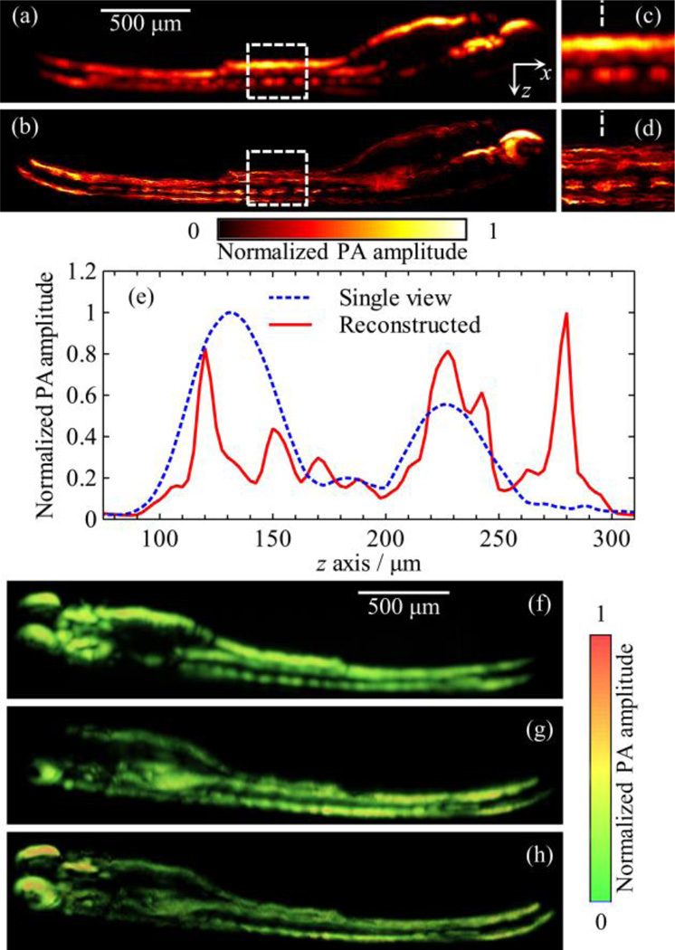
Figures 5 (a) and (b) show the maximum amplitude projections along the y axis of the single-view image at angle 0° and the reconstructed image, respectively. Figures 5 (c) and 5 (d) show the corresponding close-up features within the white dashed boxes. Figure 5 (e) shows the signal amplitudes along the white dashed lines in Fig. 5 (c) and 5 (d). Because the z axis is the depth direction, features along this direction are severely blurred in both single-view images Fig. 5 (a) and 5 (c). However, they can be easily discriminated in the reconstructed images Fig. 5 (b) and 5 (d). In addition, the PA signals are weak at the bottom of the embryo in the single-view image [Fig. 5 (a)] because upper structures absorb most of the laser energy. In contrast, these signals are recovered in the reconstructed image [Fig. 5 (b)]. Figures 5 (f) – (h) and Media 2 show volumetric renderings of two single-view 3D images and the reconstructed 3D image, respectively. Compared with either single-view image, the reconstructed image shows a significant improvement in spatial resolution and information completeness.
Fig. 5.
Single-view and reconstructed images of zebrafish ex vivo. (a) and (b) MAP images along the y axis of the single-view image at 0° and the reconstructed image of MV-OR-PAM, respectively. (c) and (d) Close-up of the region marked by the white, dashed boxes from panels (a) and (b), respectively. (e) Signal profiles along the white, dashed lines in panels (c) and (d). (f) and (g) Volumetric rendering of the two single-view images at 0° and 90°, respectively. (h) Volumetric rendering of the reconstructed image from the same angle as in (f) and (g). See Media 2 for a full view angle rendering of these three datasets.
A previous study demonstrated that one dimensional deconvolution along the depth direction can also improve axial resolution and resolution isotropy by a factor of two in OR-PAM [10]. Compared to this approach, MV-OR-PAM has achieved greater improvements in axial resolution (9-fold) and resolution isotropy (7-fold). This is because the complementary information provided by additional views facilitates solving the ill-posed deconvolution problem [15,22]. Furthermore, previous studies also show that the introduction of additional views can significantly reduce the computational cost [14,15].
Making use of the flexibility of fiber delivery, instead of rotating the sample, rotating the imaging head would be a straight-forward next step, which will make MV-OR-PAM available for more biological applications, such as high-resolution functional brain imaging and tumor model study in mouse brains and ears. Since we have demonstrated that two views are enough to achieve adequate resolution improvement, another option is to employ a dual-axis design, as in ref [13], with two near-orthogonal optical and acoustic paths. In both cases, the spatial transforms between images acquired at each view angle can be calibrated beforehand, and the reconstruction procedure is directly applicable.
5. Conclusion
To summarize, we have developed multi-view optical resolution PAM with improved axial resolution and resolution isotropy, and we have demonstrated this technique by imaging a sub-resolution microsphere phantom and a 6 dpf zebrafish embryo ex vivo. An optical resolution of 4.7 µm was experimentally quantified in 3D. Compared to the acoustically determined value in conventional OR-PAM, a 9-fold improvement in axial resolution and a 7-fold improvement in resolution isotropy have been achieved. In addition, our simulation and experimental results indicate that two nearly orthogonal views are sufficient to accomplish quasi-isotropic resolution in 3D; therefore, the high imaging speed of OR-PAM can be retained. MV-OR-PAM is expected to open up new areas of investigation in imaging translucent animals such as zebrafish and Drosophila embryos with high 3D resolution.
Acknowledgement
The authors would like to thank Prof. James Ballard for his close reading of the manuscript and an author of ref. [15], Dr. Stephan Preibisch, for discussion of multi-view deconvolution algorithms. We also thank Sarah DeGenova and Kelly Monk for helping prepare the zebrafish embryos. L. V. Wang has a financial interest in Microphotoacoustics, Inc., and Endra, Inc., which, however, did not support this work.
Funding Information
National Institutes of Health (NIH) grants DP1 EB016986 (NIH Director’s Pioneer Award), R01 CA186567 (NIH Director’s Transformative Research Award), R01 CA159959, and R01 EB016963.
Appendix
The original Lucy-Richardson deconvolution algorithm and the multi-view extended version of it assume that the image, the PSF, and the underlying object function are probability distributions, and therefore should be non-negative. This assumption imposes a unique problem in applying the multi-view Lucy-Richardson deconvolution algorithm to photoacoustic images, as the PA signals are bipolar. By taking the envelope of each A-line before reconstruction, bipolar signals become unipolar, but the strict linearity of the algorithm is breached. This breach could induce error in deconvolution along the depth direction, if only one view is used. However, since the PSF of OR-PAM is highly anisotropic, even small errors along the A-line direction in one view causes a huge penalty in the near-orthogonal view or views. Therefore, the iterative algorithm will be driven towards a more accurate estimation.
For two orthogonal views acquired at 0° and 90°, the update equations at each iteration r are as follows:
| (4) |
| (5) |
| (6) |
where u0 and u90 denote the updated terms from 0° and 90°, I is the measurement, g is the PSF, g′ is the flipped PSF, and f̂ is the estimation of the object function. The entire iteration procedure will converge towards an estimation that results in both u0 and u90 close to 1. The nonlinearity caused by envelope extraction, however, makes u0 alone favors an inaccurate f̂ along the depth direction of I0. But in OR-PAM the 3D PSF is much wider along the depth direction than along the lateral directions, so g0 is much wider than g90 along this particular direction. Thus an inaccurate f̂, favorable for u0 will generate a large u90, driving the final result to a more accurate estimation. On the contrary, an accurate f̂, favorable for u90, will produce a small u0.
The above analysis, along with our simulation and experimental results, shows that our method is viable for OR-PAM.
References
- 1.Grunwald DJ, Eisen JS. Headwaters of the zebrafish—emergence of a new model vertebrate. Nat. Rev. Genet. 2002;3:717–724. doi: 10.1038/nrg892. [DOI] [PubMed] [Google Scholar]
- 2.Bellen HJ, Tong C, Tsuda H. 100 years of Drosophila research and its impact on vertebrate neuroscience: a history lesson for the future. Nat. Rev. Neurosci. 2010;11:514–522. doi: 10.1038/nrn2839. [DOI] [PMC free article] [PubMed] [Google Scholar]
- 3.Razansky D, Distel M, Vinegoni C, Ma R, Perrimon N, Köster RW, Ntziachristos V. Multispectral opto-acoustic tomography of deep-seated fluorescent proteins in vivo. Nat. Photonics. 2009;3:412–417. [Google Scholar]
- 4.Ye S, Yang R, Xiong J, Shung KK, Zhou Q, Li C, Ren Q. Label-free imaging of zebrafish larvae in vivo by photoacoustic microscopy. Biomed. Opt. Express. 2012;3:360–365. doi: 10.1364/BOE.3.000360. [DOI] [PMC free article] [PubMed] [Google Scholar]
- 5.Wang LHV, Hu S. Photoacoustic Tomography: In Vivo Imaging from Organelles to Organs. Science. 2012;335:1458–1462. doi: 10.1126/science.1216210. [DOI] [PMC free article] [PubMed] [Google Scholar]
- 6.Wang LV, Gao L. Photoacoustic Microscopy and Computed Tomography: From Bench to Bedside. Annu. Rev. Biomed. Eng. 2014 doi: 10.1146/annurev-bioeng-071813-104553. [DOI] [PMC free article] [PubMed] [Google Scholar]
- 7.Hu S, Wang LHV. Optical-Resolution Photoacoustic Microscopy: Auscultation of Biological Systems at the Cellular Level. Biophys. J. 2013;105:841–847. doi: 10.1016/j.bpj.2013.07.017. [DOI] [PMC free article] [PubMed] [Google Scholar]
- 8.Zhang C, Maslov K, Hu S, Chen RM, Zhou QF, Shung KK, Wang LHV. Reflection-mode submicron-resolution in vivo photoacoustic microscopy. J. Biomed. Opt. 2012;17 doi: 10.1117/1.JBO.17.2.020501. [DOI] [PMC free article] [PubMed] [Google Scholar]
- 9.Wang LV, Wu H. Biomedical Optics: Principles and Imaging. John Wiley & Sons; 2012. [Google Scholar]
- 10.Zhang C, Maslov K, Yao JJ, Wang LHV. In vivo photoacoustic microscopy with 7.6-mu m axial resolution using a commercial 125-MHz ultrasonic transducer. J. Biomed. Opt. 2012;17 doi: 10.1117/1.JBO.17.11.116016. [DOI] [PMC free article] [PubMed] [Google Scholar]
- 11.Xie ZX, Chen SL, Ling T, Guo LJ, Carson PL, Wang XD. Pure optical photoacoustic microscopy. Opt. Express. 2011;19:9027–9034. doi: 10.1364/OE.19.009027. [DOI] [PMC free article] [PubMed] [Google Scholar]
- 12.Shelton RL, Mattison SP, Applegate BE. Volumetric imaging of erythrocytes using label-free multiphoton photoacoustic microscopy. J Biophotonics. 2013 doi: 10.1002/jbio.201300059. [DOI] [PubMed] [Google Scholar]
- 13.Zhu L, Gao L, Li L, Wang L, Ma T, Zhou Q, Shung KK, Wang LV. Cross-optical-beam nonlinear photoacoustic microscopy. Proc. SPIE (International Society for Optics and Photonics. 2014;8943:89433H–89433H. [Google Scholar]
- 14.Wu Y, Wawrzusin P, Senseney J, Fischer RS, Christensen R, Santella A, York AG, Winter PW, Waterman CM, Bao Z. Spatially isotropic four-dimensional imaging with dual-view plane illumination microscopy. Nat. Biotechnol. 2013 doi: 10.1038/nbt.2713. [DOI] [PMC free article] [PubMed] [Google Scholar]
- 15.Preibisch S, Amat F, Stamataki E, Sarov M, Myers E, Tomancak P. Efficient Bayesian-based multi-view deconvolution. Nat. Methods. 2014;11:645–648. doi: 10.1038/nmeth.2929. [DOI] [PMC free article] [PubMed] [Google Scholar]
- 16.Richardson WH. Bayesian-based iterative method of image restoration. JOSA. 1972;62:55–59. [Google Scholar]
- 17.Lucy L. An iterative technique for the rectification of observed distributions. Astron. J. 1974;79:745. [Google Scholar]
- 18.Li L, Yeh C, Hu S, Wang L, Soetikno BT, Chen R, Zhou Q, Shung KK, Maslov KI, Wang LV. Fully motorized optical-resolution photoacoustic microscopy. Opt. Lett. 2014;39:2117–2120. doi: 10.1364/OL.39.002117. [DOI] [PMC free article] [PubMed] [Google Scholar]
- 19.Preibisch S, Saalfeld S, Schindelin J, Tomancak P. Software for bead-based registration of selective plane illumination microscopy data. Nat. Methods. 2010;7:418–419. doi: 10.1038/nmeth0610-418. [DOI] [PubMed] [Google Scholar]
- 20.Tikhonov AN, Arsenin VI, John F. Solutions of Ill-Posed Problems. Washington, DC: Winston; 1977. [Google Scholar]
- 21.Gao L, Zhu L, Li C, Wang LV. Nonlinear light-sheet fluorescence microscopy by photobleaching imprinting. J. R. Soc. Interface. 2014;11:20130851. doi: 10.1098/rsif.2013.0851. [DOI] [PMC free article] [PubMed] [Google Scholar]
- 22.Krzic U. Multiple-view microscopy with light-sheet based fluorescence microscope. Heidelberg University. 2009 [Google Scholar]


