Abstract
The tripartite anthrax toxin consists of protective antigen (PA), lethal factor (LF), and edema factor (EF). PA63 (the 63 kDa, C-terminal part of PA) forms heptameric channels in cell membranes that allow for the transport of LF and EF into the cytosol. These channels are mushroom-shaped, with a ring of seven phenylalanine residues (known as the phenylalanine clamp) lining the junction between the cap and stem. It is known that when LF is translocated through the channel, the phenylalanine clamp creates a seal that causes an essentially complete block of conduction. In order to examine ion conductance in the stem of the channel, we used Venus yellow fluorescent protein (YFP) as a molecular stopper to trap LFN (the 30 kDa, 263-residue N-terminal segment of LF), and various truncated constructs of LFN, in mutant channels in which the phenylalanine clamp residues were mutated to alanines. Here we present evidence that ion movement occurs within the channel stem (but is stopped, of course, at the phenylalanine clamp) during protein translocation. Furthermore, we also propose that the lower region of the stem plays an important role in securing peptide chains during translocation.
Keywords: protein translocation, ion-conducting channels, phenylalanine clamp, conductance block, single channels
Introduction
Anthrax toxin consists of three proteins: edema factor (EF; 89 kDa), lethal factor (LF; 90 kDa), and protective antigen (PA; 83 kDa). The former two are enzymes (EF is an adenylate cyclase1 and LF is a protease2, 3) which exert their toxic effects when present in the cell’ cytosol. They can gain access to the cytosol, however, only in binary combination with PA. PA forms channels in cell membranes that facilitate the transport of EF and LF into cells (for a general review of anthrax toxin, see reference 4). Channel formation begins when PA83 binds to a receptor on the cell surface and is cleaved by a furin-like protease, which detaches a 20 kDa segment from the N-terminus. The remaining 63 kDa (PA63) segment stays attached to the receptor and heptamerizes4 (or octamerizes5) to form a prepore that can bind a maximum of three ligands (EF/LF). These ligand-receptor complexes are then taken up into the cell via endocytosis and end up in an acidic vesicular compartment. The low pH in this vesicle causes the prepore to form the (PA63)7 channel in the vesicular membrane, through which LF and EF can then pass into the cytosol4. Understanding the mechanism by which this translocation occurs may elucidate general principles of protein translocation across cell membranes.
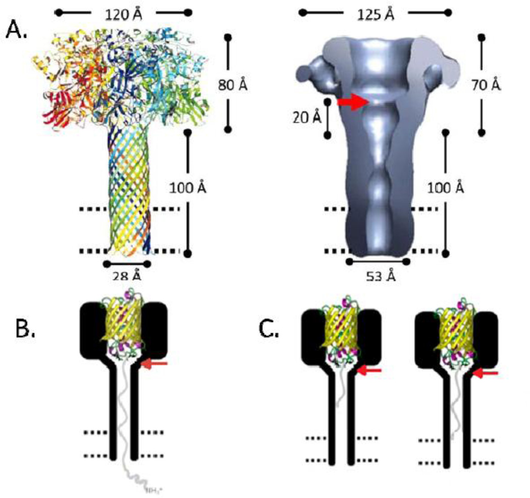
The (PA63)7 channel (Figure 1A) is mushroom-shaped, with a globular cap domain and a cylindrical stem domain6, 7. The stem is an extended 14-stranded β-barrel, roughly 100 Åring; long (25 Åring; crossing the lipid bilayer and 75 Åring; extending from it)8, 9. (PA63)7 can be reconstituted in a planar lipid bilayer membrane, forming cation-selective channels with a conductance of ~55 pS (in 100 mM KCl, pH 5.5)10. It has been shown that LFN (the 30 kDa, 263-residue N-terminal segment of LF), as well as whole EF and LF, can be translocated through these channels, N-terminus first, by applying positive voltages to the cis solution (the solution to which (PA63)7 was added)11, 12 as well as by establishing a pH gradient across the membrane13. In this system, LFN (in the fully extended state14) passes from the cis solution, through the channel stem, and into the opposite trans solution15.
Figure 1.
A14Left: Model of (PA63)76Right: Structure of (PA63)7, determined by negative-stain electron microscopy (~25 Åring; resolution)7. The red arrow denotes the presumed position of the ϕ-clamp; the 20 Åring; bar represents the distance from the ϕ-clamp to the presumed beginning of the stem; the dashed parallel lines represent the lipid bilayer. B. LFN-YFP trapped in (PA63F427A)7 at +50 mV. YFP is represented as a yellow β-barrel; LFN is represented as a grey line; the bilayer is represented as parallel dashed lines. The red arrow indicates the position at which the phenylalanine residues of the ϕ-clamp were mutated to alanine residues (adapted from reference 14). C. Truncated versions of LFN-YFP trapped in (PA63F427A)7 at +50 mV. YFP is represented as a yellow β-barrel; LFN is represented as a grey line; the bilayer is represented as parallel dashed lines. The red arrow indicates the position at which the phenylalanine residues of the ϕ-clamp were mutated to alanine residues (adapted from reference 14).
A ring of seven phenylalanine residues (F427), known as the “phenylalanine clamp” (ϕ-clamp), lies near the junction between the cap and stem of (PA63)7 and is important for LFN translocation. The bulky ϕ-clamp residues form a narrow “iris” in the channel that binds LFN stably in the lumen, causing an effectively complete block in conduction10. It is not known, however, whether the stem of the channel allows for any conduction during LFN translocation; that is, whether ions can move from the trans entrance of the channel into the stem. This question has important implications regarding the forces involved in voltage-driven translocation: namely, whether the electric field is focused at the ϕ-clamp (if ions can enter the stem) or decays along the length of the channel (if ions cannot enter the stem). In this paper, we demonstrate that in the absence of the ϕ-clamp, ion conductance is not completely blocked in the stem of the channel when the stem is occupied by LFN. That is, the electrical resistance of the stem is much lower than that across the ϕ-clamp. We also find that the lower region of the stem (near the trans end of the channel) appears to better secure the translocating species in the channel than does the upper region.
General Strategy
The ϕ-clamp completely blocks ion conduction during LFN translocation. Thus, with the ϕ-clamp present we cannot determine whether ions can enter the stem from the trans solution when it is occupied by LFN. Mutating the phenylalanine residues of the ϕ-clamp to alanines removes the block10 and thereby allowed us to observe to what extent, if any, ions may permeate the stem of the channel during LFN translocation.
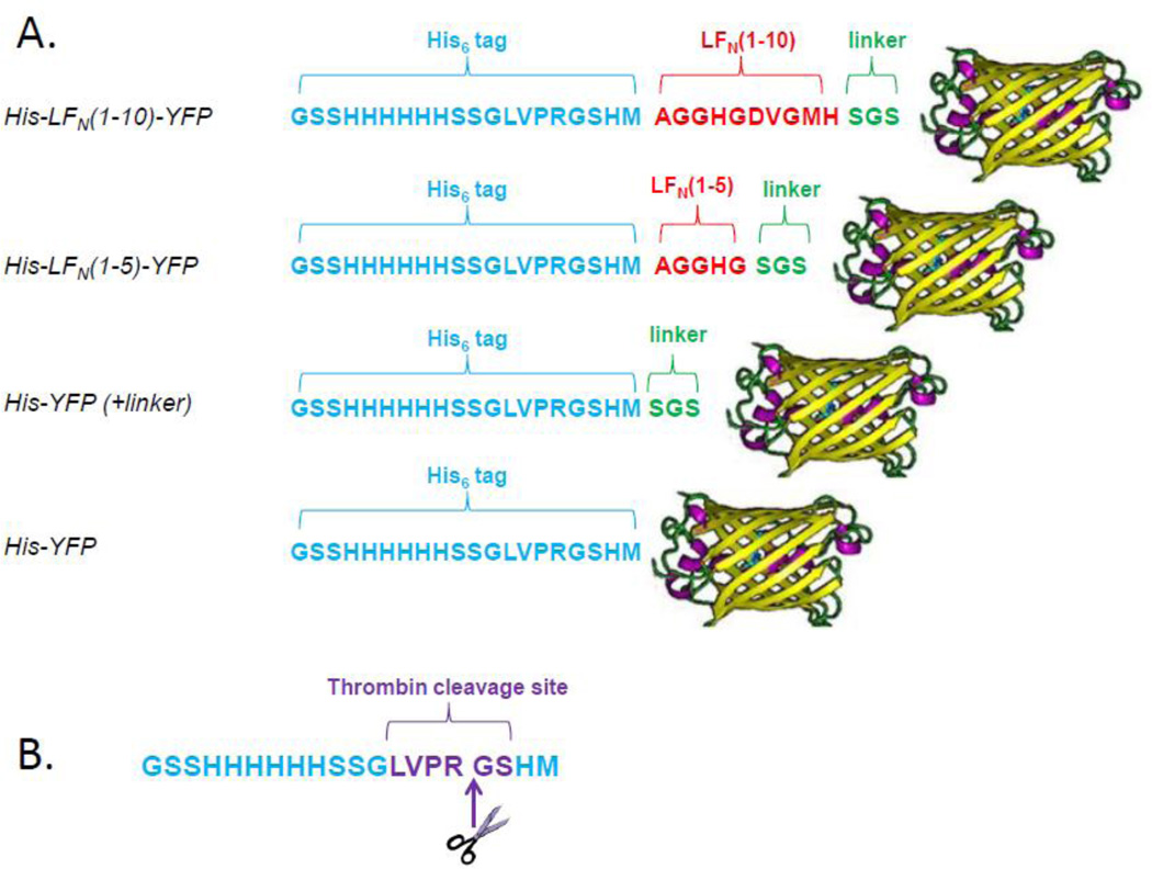
To anchor LFN in the stem and prevent its complete translocation, we attached YFP (yellow fluorescent protein) to the C-terminus of LFN (Figure 1B). YFP acted as a molecular stopper because it was too large to enter the stem of the anthrax toxin channel14 (even when the ϕ-clamp was mutated). This allowed us to trap the translocating species in the channel at positive voltages, since LFN-YFP was unable to pass out into the trans solution (YFP is assumed to be stopped at the ϕ-clamp; for a comprehensive explanation of this strategy, see reference 14). In addition to generating LFN-YFP and His-LFN-YFP (His6-tagged LFN-YFP), we also performed deletions from the C-terminus of LFN (as described in reference 14) in order to create a series of truncated versions of both LFN-YFP and His-LFN-YFP (Figure 2), which are too short to traverse the entire length of the channel (as measured from the ϕ-clamp to the bottom of the stem).
Figure 2.
A. Schematic of selected truncated His-LFN-YFP constructs. The N-terminal 20-residue His6-tag is shown in blue, LFN residues are shown in red, linker residues are shown in green, and the C-terminal YFP is shown as a yellow β-barrel. B. 20-residue His6-tag. Note that the N-terminal methionine residue encoded by pET-15b is not present, as it is removed during protein expression25. The site of thrombin cleavage is shown in purple, with the cleavage taking place between the arginine and glycine residues. Thrombin treatment removes the first 16 residues of the tag, leaving behind four residues (Gly-Ser-His-Met).
We performed macroscopic and single-channel electrophysiological experiments using mutant (PA63)7 channels in which the phenylalanine residues of the ϕ-clamp were mutated to less bulky alanine residues ((PA63F427A)7). These mutant channels have a conductance of ~110 pS (in 100 mM KCl, pH 5.5)10. We used cis positive voltages of +20 mV and +50 mV to drive both the full-length and truncated constructs into (PA63F427A)7 channels (Figures 1B and 1C) in planar lipid bilayers in order to observe the extent of ion conduction in the channel stem when either fully or partially occupied by an inserted protein segment. At +50 mV, LFN and the His6-tag are expected to be fully extended into the channel; the degree of extension at +20 mV is not clear14.
Results
Cis effect of LFN-YFP, His-LFN-YFP, and truncated constructs on conductance of (PA63F427A)7 channels
Macroscopic experiments
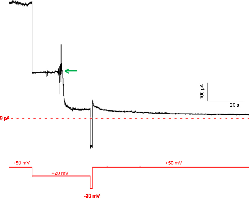
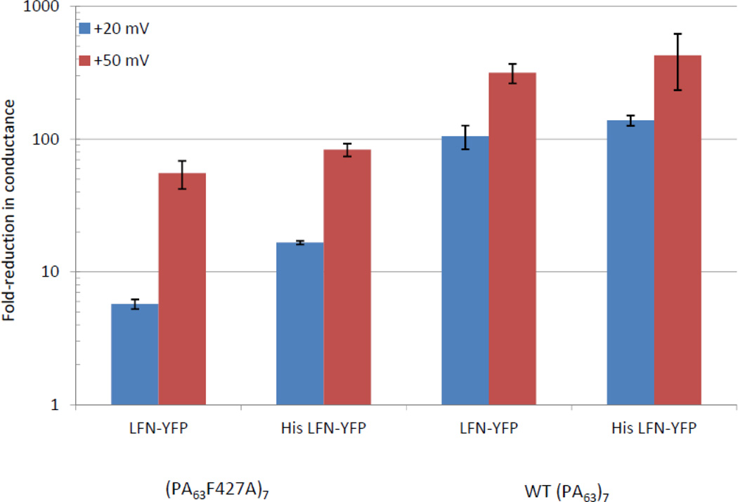
Cis addition of saturating amounts of LFN-YFP to membranes containing hundreds of (PA63F427A)7 channels (see Figure 3 for a typical record) yielded a ~50-fold reduction in conductance at +50 mV, which was noticeably less than the ~300-fold reduction in conductance observed after cis addition of LFN-YFP to membranes containing WT (PA63)7 channels (Figure 4). This difference was even more pronounced at +20 mV (a voltage at which LFN is not expected to be completely unfolded and/or completely extended through the channel14,15), where there was only a ~6-fold reduction in conductance in the mutant channel and a ~90-fold reduction in the WT channel (Figure 4). Cis addition of His-LFN-YFP to both WT and mutant channels yielded comparable results, with much greater block of WT than of mutant channels (Figure 4).
Figure 3.
Record of cis addition of LFN-YFP to a membrane containing (PA63F427A)7 channels. After the current (shown as a black line) produced by (PA63F427A)7 channels reached a steady-state at both +50 mV and +20 mV, LFN-YFP was added at the green arrow to a final concentration of ~0.2 µM (voltage held at +20 mV), reducing the current by a factor of ~6. After the current reached a new steady-state, the channels were unblocked by applying a voltage of −20 mV, and subsequently re-blocked by applying a voltage of +50 mV, causing the current to be reduced by a total factor of ~50. Voltage is shown as a solid red line; the zero baseline of current is shown as a dashed red line.
Figure 4.
Cis effect of saturating concentrations (~0.2 µM) of LFN-YFP and His-LFN-YFP on conductance of (PA63F427A)7 and WT (PA63)7 channels at +20 mV and +50 mV. All experiments were performed in triplicate; error bars represent standard error.
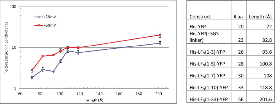
We next determined the macroscopic block in conductance produced by truncated versions of LFN-YFP and His-LFN-YFP. The distance required to span the length of the channel, from the ϕ-clamp to the bottom of the stem, is approximately 120 Åring; (YFP is presumed to be stopped at the ϕ-clamp when these constructs are driven into the channels at positive voltages14). The His-tagged series of truncated constructs (Figure 5) that did not span the entire length of the stem ranged from lengths of 72 Åring; (His-YFP, which is just YFP with a His6-tag attached) to 119 Åring; (His-LFN (1–10)-YFP, which is YFP with three linker residues, the first 10 residues of LFN, and a His6-tag). These lengths are based on each residue spanning a distance of ~3.6 Åring; in an extended peptide chain14, 16. We also created a construct that was 202 Åring; long (His-LFN (1–33)-YFP), which is long enough to extend past the bottom of the channel when fully extended, but still much shorter than full-length His-LFN-YFP (1030 Åring;).
Figure 5.
Left. Cis effect of saturating concentrations (~0.47 µM) of truncated His-LFN-YFP constructs on conductance of (PA63F427A)7 channels at +20 and +50 mV. All experiments were performed in triplicate; error bars represent standard error (bars that are not visible are small enough that they are obscured by the marker). Right. List of truncated His-LFN-YFP constructs and the number of amino acids/length of each (not including YFP, which is presumed not to unwind when positive voltages are applied). All of the constructs contain a 20-residue His6-tag, as well as a Ser-Gly-Ser linker before YFP, except for His-YFP (the first construct on the list), which is just the His6-tag attached directly to YFP.
The cis effect of the His6-tagged series of truncated constructs on (PA63F427A)7 channels is shown in Figure 5. Overall, as the length of the construct increased, there was a greater block in conductance at both +20 mV and +50 mV. Additionally, the block in conductance produced by these constructs was less than that observed with full-length His-LFN-YFP (Figure 4) at both +20 mV and + 50 mV.
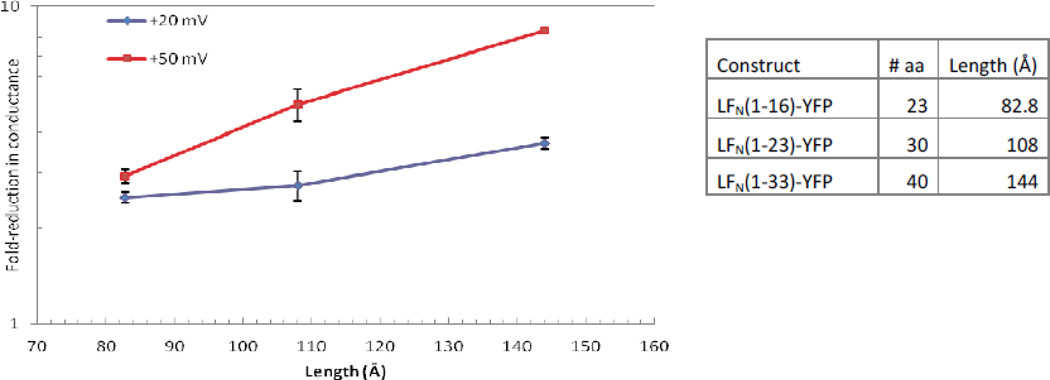
The cis effect of truncated LFN-YFP constructs on the conductance of (PA63F427A)7 channels at +20 mV and +50 mV (Figure 6) was similar to the overall effect observed with truncated His-LFN-YFP constructs (Figure 5). While the general trend of the extent of the block increasing with the length of the construct holds true here as well, the His-tagged series produced a greater reduction in conductance (Figure 5). Compare, for example, the 5-fold block in conductance produced by the cis addition of LFN(1–23)-YFP (108Åring; in length) to (PA63F427A)7 channels at +50 mV (Figure 6) versus the 10-fold block produced by His-LFN(1–23)-YFP (also 108Åring; in length; Figure 5). As the anthrax toxin channel is cation-selective, the greater block in conductance produced by the His-tagged series may be due to the repulsion of cations by the six consecutive histidine residues of the His6-tag, assuming that the cation selectivity of the peptide-occupied stem is comparable to that of the unoccupied stem.
Figure 6.
Left. Cis effect of saturating concentrations (~0.47 ~M) of truncated LFN-YFP constructs on the conductance of (PA63F427A)7 channels at +20 mV and +50 mV. All experiments were performed in triplicate; error bars represent standard error (bars that are not visible are small enough that they are obscured by the marker). Right. List of truncated LFN-YFP constructs and the number of amino acids/length of each (not including YFP, which is presumed not to unwind when positive voltages are applied). All of the constructs contain four residual residues from the His6-tag (which was cleaved by thrombin), followed by the specified LFN residues as well as a Ser-Gly-Ser linker before YFP.
Single-channel experiments
The cis addition of full-length LFN-YFP (or His-LFN-YFP) to (PA63F427A)7 channels produced, at the macroscopic level, less of a block in conductance than when added to WT (PA63)7 channels (Figure 4). This can be interpreted in one of two ways. It is possible that this difference reflects the relative times that these channels remain occupied by LFN. However, it is also possible that this difference reflects a discrepancy in the degree of block when a channel is occupied by LFN. To distinguish between these two possibilities, we performed single-channel experiments.
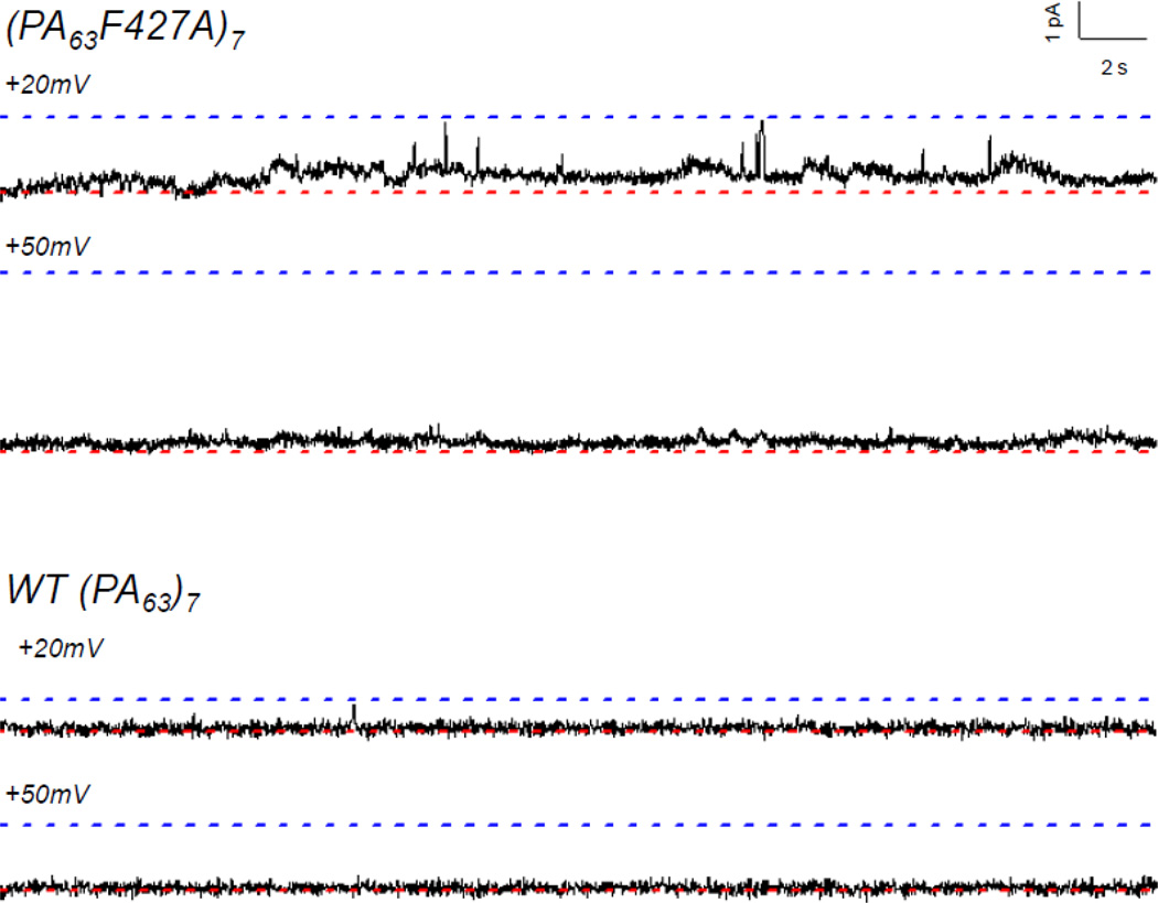
Single-channel experiments (Figure 7) revealed that LFN-YFP remains mostly secure in the (PA63F427A)7 channel (as in the wild-type channel) at both +20 mV and +50 mV; thus, the residual ion conductance observed at the macroscopic level must be due to the presence of small intermediate conductance states that are not observed in the WT channel, but which we see in the mutant channel (Figure 7). Therefore, these results indicate that there is indeed a “leak” in the stem of the anthrax toxin channel that allows ions to enter it (from the trans side) during LFN translocation. Note that while this small residual conductance may be difficult to discern at the single-channel level, particularly at +50 mV, it is easily measured at the macroscopic level (Figure 4). Similar single-channel records were obtained for His-LFN-YFP in both mutant and WT channels (not shown).
Figure 7.
Single-channel records of cis effect of LFN-YFP on conductance of (PA63F427A)7 (top) and WT (PA63)7 (bottom) channels at +20 mV and +50 mV. For each record, the upper dashed blue line represents the open state and the lower dashed red line represents the completely blocked (or closed) state. (The open-state conductance of the mutant channel is roughly double that of the WT channel at both +20 mV and +50 mV.) Note that the conductance of the WT (PA63)7 channel is completely blocked by LFN-YFP, whereas there is a small residual conductance at both +20 mV and +50 mV in the (PA63F427A)7 channel. Records are 35 seconds long and filtered at 15 Hz.
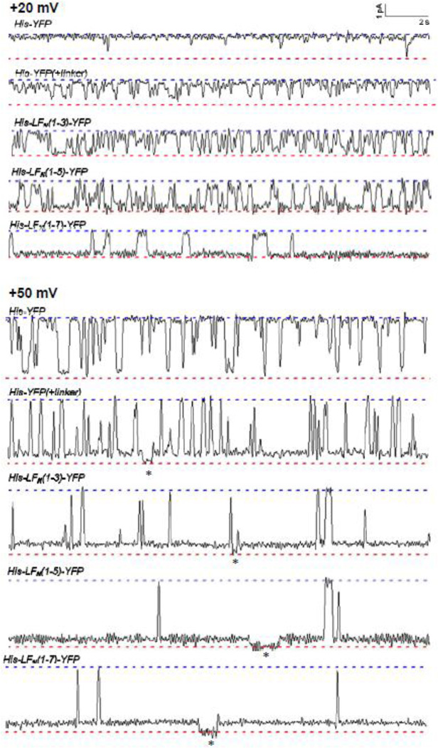
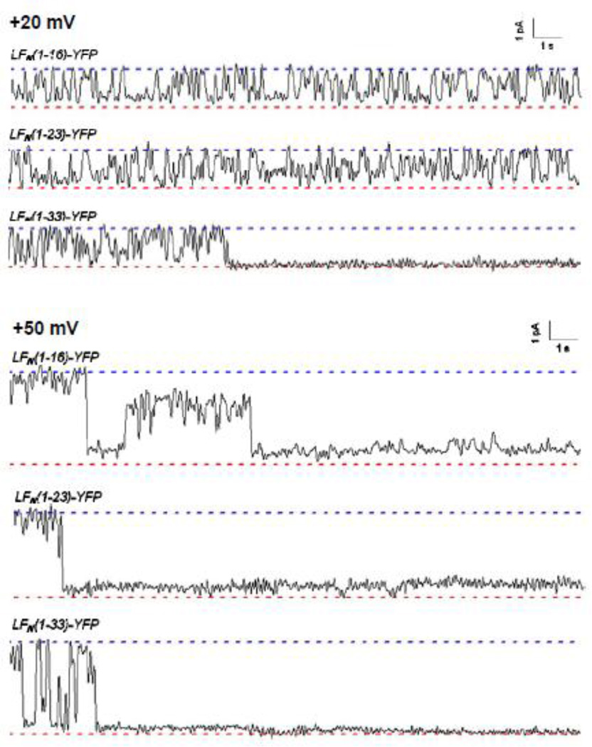
On the other hand, single-channel experiments demonstrated that the incomplete block in conductance observed with the truncated His-LFN-YFP and LFN-YFP constructs is a reflection of both the relative amount of time the peptide chain occupies the channel as well as small intermediate states of conductance even when the chain is secure in the channel (Figures 8 and Figure 9). Experiments with the shortest truncated His-LFN-YFP constructs revealed that there is quite a bit of flickering in and out of the channel at both +20 mV and +50 mV (Figure 8), which presumably indicates that the peptide chain is not secure in the channel. However, as the length of the His6-tagged construct increases, the chain appears to be far more secure in the channel, particularly at +50 mV. For example, His-LFN (1–7)-YFP, which produced only a 10-fold reduction in macroscopic conductance at +50 mV, hardly flickers out of the channel at all at this voltage (Figure 8). (Importantly, the same mean fractional block of conductance was observed on the single-channel level as on the macroscopic level, ~90%.) However, note that at least some of the residual conductance observed with His-LFN (1–7)-YFP may be attributed to an incomplete block in conductance even when the peptide chain is secure within the channel. Indeed, there appear to be two blocked substates at +50 mV: one where ~ 90% of the open-channel conductance is blocked and one where closer to 100% of the open-channel conductance is blocked. The first substate appears the majority of the time. A similar incompletely-blocked substate is observed in experiments with the truncated LFN-YFP constructs as well (Figure 9).
Figure 8.
Single-channel records of the cis effect of selected truncated His-LFN-YFP constructs on the conductance of (PA63F427A)7 channels at +20 mV (top) and +50 mV (bottom). For each construct, the upper dashed blue line represents the open state and the lower dashed red line represents the completely blocked (or closed) state. Note the incomplete block at +50 mV; the asterisks indicate the brief moments where a given channel enters a completely blocked (or closed) state. Also note that the conductance fluctuations are reminiscent of those seen with tethered DNA26. Records are 20 seconds long and filtered at 10 Hz.
Figure 9.
Single-channel records of the cis effect of truncated LFN-YFP constructs on the conductance of (PA63F427A)7 at +20 mV (top) and +50 mV (bottom). For each construct, the upper dashed blue line represents the open state and the lower dashed red line represents the completely blocked (or closed) state. Records are 20 seconds long and filtered at 10 Hz. In the record for LFN(1–33)-YFP at +20 mV, there was subsequent unblocking later on.
Trans effect of His-YFP and LFN (1–16)-YFP constructs on conductance of (PA63F427A)7 channels
There were two motivating factors for studying the trans effect of selected truncated His-LFN-YFP and LFN-YFP constructs on the conductance of (PA63F427A)7 channels. The first was to ensure that the β-barrel structure of the (PA63F427A)7 channel stem was not significantly perturbed by the ϕ-clamp mutation. If the trans addition of truncated constructs that were not long enough to reach the ϕ-clamp (from the bottom of the stem) produced similar blocking effects in both mutant and WT channels, it would indicate that the stem of the (PA63F427A)7 channel was structurally intact.
The second factor was that the single-channel cis experiments with truncated His-LFN-YFP (Figure 8) seemed to indicate that the lower region of the channel stem is important for securing the translocating species in the channel. Note that His-YFP, which is 72 Åring; long (and spans almost 2/3 of the ~120 Åring; distance from the ϕ-clamp to the bottom of the stem), flickers in and out of the channel rapidly. As the length of the construct extends further into the lower region of the channel stem, the construct hardly pops out of the channel at all. We therefore anticipated that His-YFP and LFN (1–16)-YFP (82.8 Åring; long) would be held more securely in the channel when added to the trans side instead of the cis side.
Macroscopic experiments
In trans experiments, the voltage protocol is reversed, so that negative voltages produce blocking and positive voltages produce unblocking. We were unable to observe the blocking effect produced at −50 mV due to the intrinsic voltage-dependent gating of these channels. However, even at −20 mV we observed a stark difference between the block produced by His-YFP and LFN (1–16)-YFP when driven into (PA63F427A)7 channels from the trans side versus the cis side.
At the macroscopic level, His-YFP produced a ~6-fold reduction in conductance when added to the trans side of (PA63F427A)7 channels at −20 mV (Figure 10A), as opposed to the cis effect of a ~2-fold reduction at +20 mV (Figure 5). Likewise, whereas we observed only a ~2.5-fold block in conductance when adding LFN(1–16)-YFP to the cis side of (PA63F427A)7 channels at +20 mV (Figure 6), trans addition produced an ~11-fold block in conductance at −20 mV (Figure 11A). We repeated these experiments with WT channels and obtained comparable results (data not shown).
Figure 10.
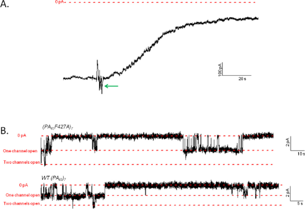
A. Record of trans addition of 0.47 µM His-YFP to a membrane containing (PA63F427A)7 channels. After the current (shown as a black line) produced by (PA63F427A)7 channels reached a steady state at −20 mV, His-YFP was added at the green arrow (voltage held at −20 mV), reducing the current by a factor of ~6. The zero baseline of current is shown as a dashed red line. B. Single-channel records of the trans effect of His-YFP on the conductance of membranes containing two (PA63F427A)7 channels (top) and two WT (PA63)7 channels (bottom) at −20 mV. Subsequent unblocking at +20 mV (not shown) confirmed that both channels were still present. The three dashed red lines in each record represent, respectively, the zero baseline of conductance, the open state conductance of one channel, and the open state conductance of two channels. Top record is 170 seconds long and bottom record is 90 seconds long; both are filtered at 10 Hz.
Figure 11.
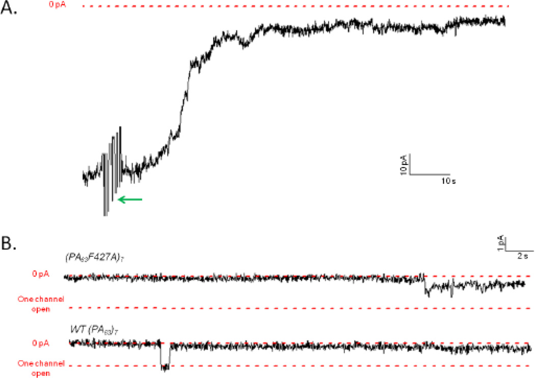
A. Record of trans addition of 0.47 µM LFN(1–16)-YFP to a membrane containing (PA63F427A)7 channels. After the current (shown as a black line) produced by (PA63F427A)7 channels reached a steady state at −20 mV, LFN(1–16)-YFP was added at the green arrow (voltage held at −20 mV), reducing the current by a factor of ~11. The zero baseline of current is shown as a dashed red line. B. Single-channel records of the trans effect of LFN(1–16)-YFP on the conductance of membranes containing one (PA63F427A)7 channel (top) and one WT (PA63)7 channel (bottom) at −20 mV. Note the intermediate substates in both records. (The intermediates are smaller in the WT channel as its conductance is roughly half that of the mutant channel.) Subsequent unblocking at +20 mV (not shown) confirmed that the channel was still present. The two dashed red lines in each record represent, respectively, the zero baseline of conductance and the open state conductance of one channel. Record is 35 seconds long and filtered at 10 Hz.
Single-channel experiments
At the single-channel level, the trans addition of His-YFP to (PA63F427A)7 channels revealed that the channel stem is able to secure His-YFP most of the time (Figure 10B). It is clear that the peptide chain occupies the channel for a far greater amount of time when added from the trans side instead of from the cis side (compare Figure 10B to Figure 8), supporting our proposal that the lower region of the stem is important for securing the translocating species in the channel. Single-channel trans experiments also confirmed that LFN(1–16)-YFP is able to remain securely in the mutant channel for the majority of the time (Figure 11B).
We once again repeated these experiments using WT channels and obtained records that were quite similar to the experiments with the mutant channels for both His-YFP (Figure 10B) and LFN (1–16)-YFP (Figure 11B). Importantly, LFN (1–16)-YFP produced intermediate states of conductance in both WT and mutant channels, which seems to indicate that the β-barrel structure of the (PA63F427A)7 channels has not been grossly perturbed.
Discussion
In this paper, we have addressed the question of whether the stem of the mushroom-shaped anthrax toxin channel allows for ion movement within it during protein translocation. We found that whereas there is complete ion conduction block at the ϕ-clamp, there is substantial, but incomplete, block by the polypeptide chain in the stem, and we further characterized the extent of the macroscopic block as a function of the length of the peptide chain. The block may be both a steric one and an electrostatic one arising from charges on the polypeptide chain. This latter, in fact, may account for the larger blocking effects produced by the constructs having a His6-tag at the N terminus (compare Figures 5 and 6). We also observe a greater block at +50 mV than at +20 mV, since although the peptide chain likely adopts a fully-extended configuration inside the channel at both voltages, at +20 mV the chain is expected to spend less time further down in the channel than at +50 mV, due to Brownian motion. All of the implications of this finding for LFN translocation through the (PA63)7 channels are not yet clear, but one thing is certain: in considering voltage-driven translocation, one must now recognize that most of the applied voltage is dropped across the ϕ-clamp and not along the stem.
It is possible that the mutation of the phenylalanines at the ϕ-clamp to alanines has modified the channel’ stem so that the incomplete conductance block there does not hold true for the wild-type stem. This, however, is unlikely, as in both macroscopic and single-channel (Figures 10B and 11B) experiments, the trans addition of His-YFP and LFN(1–16)-YFP produced comparable results on WT (PA63)7 and (PA63F427A)7 channels.
That there exists an incomplete block of conductance in the channel stem during protein translocation has been suggested previously in studies of pH-driven translocation in WT (PA63)7 and (PA63F427A)7 channels13. The rate of pH-driven translocation is significantly slowed when the ϕ-clamp is mutated to alanines; it has been proposed that this effect is a result of the collapse of the pH-gradient due to a small amount of protons “leaking” through the mutant channel13, 17. Our demonstration that there is indeed a small residual conductance in the channel stem certainly bolsters this claim. Furthermore, prior voltage-driven translocation studies have also demonstrated evidence of leaky sub-conductance states; the cis addition of LFN to (PA63F427A)7 at +20 mV yields intermediate states of conductance10.
In addition to the incomplete block of ion conductance in the channel stem during LFN translocation, another feature of the stem is revealed from our experiments with truncated versions of His-LFN-YFP that were not long enough to completely transverse the stem. Namely, the securing of the polypeptide chain within the channel stem appears to reside in the lower third of the stem. This was evidenced from the experiments in which His-LFN-YFP constructs of various lengths were added to the cis solution (Figure 8) and was confirmed by the addition of the short His-YFP to the trans solution (Figure 10B). The implication is that the lumen of the stem narrows in its lower region, although one cannot preclude specific binding interactions between residues in the stem and those on the polypeptide chain. We must also acknowledge the possibility of YFP partially unfolding, which would obscure the length of the chain that is present in the channel, but we believe this is unlikely (for a further discussion of this matter, see reference 14).
We cannot ignore the possibility that the large block in conductance produced when adding His-YFP (or LFN(1–16)-YFP) to the trans side of both mutant and WT channels is due simply to the binding of YFP to residues on the trans end of the channel, or to the lipid bilayer adjacent to the trans entrance to the channel. However, we believe these scenarios to be unlikely. First, in experiments in which the bottom-most residues (F313 and F314) of the (PA63)7 channel stem were mutated to alanines, adding His-YFP to the trans side of these channels produced the same degree of block observed with WT channels (unpublished results). Second, studies have shown that YFP does not have strong associations with the lipid bilayers of plasma membranes18.
One last point: the single-channel records reported here are highly filtered (10–15 Hz) and therefore are not very revealing of the magnitudes of the sub-states and their dwell times. Future experiments at much higher time resolution are contemplated. These will give a finer picture of the Brownian motion and drift of the polypeptide chain within the stem.
Materials and Methods
Molecular biology and protein purification
His-LFN-YFP protein, with a His6-tag attached to the N-terminus of LFN and Venus YFP fused at its C terminus, was constructed as described previously14. Briefly, the pET-15b plasmid (Novagen) encodes a thrombin-cleavable His6-tag sequence (Merck) into which was cloned LFN residues 1–263, followed by a serine-glycine-serine linker, followed by Venus YFP, for a total insert of 503 residues.
In order to create truncated constructs, complementary mutagenic oligonucleotides were used to delete central segments of His-LFN-YFP. Using the QuikChange Site-Directed Mutagenesis kit, the following constructs were generated (in all of these constructs, the 20-residue His6-tag is attached at the N-terminus and the YFP is attached at the C-terminus): His-YFP (LFN and the linker residues were deleted), His-YFP (with the linker residues included), His-LFN(1–3)-YFP, His-LFN(1–5)-YFP, His-LFN(1–7)-YFP, His-LFN(1–10)-YFP, His-LFN(1–16)-YFP, His-LFN(1–23)-YFP and His-LFN(1–33)-YFP (see Figure 2 for representative schematic constructs).
His-LFN-YFP and the truncated constructs were expressed recombinantly and purified as previously described10, 12, 14, 19, 20. Wild-type (PA63)7 (trypsin-nicked PA83 from which PA20 was removed21) was a gift from Dr. Sen Zheng. Mutant (PA63F427A)7 was the same sample previously reported10. In some of the experiments, the His6-tags on His-LFN-YFP and the various truncated constructs were cleaved with thrombin according to the Novagen manual protocol (Figure 2).
Planar lipid bilayers
Planar lipid bilayers were formed via the brush technique22 across a 0.5 mm hole in a 125-µm-thick Teflon partition. The membranes separated two Lucite compartments that each contained 3 mL of 100 mM KCl, 25 mM potassium-succinate, 1 mM EDTA, pH 5.5. In experiments in which we wished to reduce the noise level further, membranes were formed across a 100-µm diameter aperture in a polystyrene cup23; the front compartment contained 1.5 mL of solution and the rear compartment contained 0.75 mL. The individual compartments were stirred using small magnetic stir bars. Agar salt bridges (3M KCl, 3% agar) connected Ag/AgCl electrodes in saturated KCl solutions to the cis and trans compartments. The membrane-forming solution was 3% diphytanoyl-phosphatidylcholine (Avanti Polar Lipids, Inc.) in n-decane; membrane formation was observed visually. All experiments were performed under voltage clamp conditions; voltages are those of the cis solution (to which (PA63)7 or (PA63F427A)7 prepore heptamer was added) in reference to the trans solution (held at virtual ground). Current responses were filtered at 10–15 Hz by a low-pass eight-pole Bessel filter (Warner Instruments) and recorded on a DMP-4B Physiograph chart recorder, as well as an NI USB-6211 Data Acquisition Board (National Instruments) for digital storage14, 24.
(PA63)7 channel formation and conductance block
Following membrane formation, either wild-type (PA63)7 or (PA63F427A)7 prepore heptamer was added to the cis compartment, which was held at a voltage of +20 mV with respect to the trans compartment. When the conductance produced by (PA63)7 channel formation reached a steady-state, LFN-YFP (or His-LFN-YFP or one of the truncated constructs) was added to the cis compartment at near-saturating concentrations (~0.2 µM for His-LFN-YFP and LFN-YFP; ~0.47 µM for truncated His-LFN-YFP and LFN-YFP constructs). The blocking of the channels by LFN-YFP or one of its variants was monitored by the fall in conductance at +20 mV and +50 mV (a typical record is shown in Figure 3). In the trans experiments, the voltage was held at −20 mV, and the truncated constructs were added to the trans compartment.
The protocol for single-channel experiments was the same, except that only one or two channels were allowed to form (by adding dilute amounts of (PA63)7 or (PA63F427A)7 prepore heptamer).
Highlights.
Ion conduction in the stem of the anthrax toxin channel is analyzed.
Block in conductance in the channel stem is incomplete during protein translocation.
The lower region of the stem may secure the peptide chain during translocation.
Acknowledgements
We thank Karen Jakes, Paul Kienker, Russell Thomson, and Eshwar Udho for their assistance in performing the experiments described in this paper. We also thank Myles Akabas, Karen Jakes, and Paul Kienker for their helpful comments on the manuscript, and Daniel Basilio for the use of his plasmids.
This work was supported by National Institutes of Health research grant GM 29210.
Abbreviations used in this paper
- PA
protective antigen
- LF
lethal factor
- EF
edema factor
- PA63
63 kDa C-terminal portion of PA
- (PA63)7
the heptameric form of PA63
- LFN
the 30 kDa, 263-residue N-terminal segment of LF
- ϕ-clamp
phenylalanine clamp
- YFP
yellow fluorescent protein
- LFN-YFP
LFN with YFP attached to its C-terminus
- His-LFN-YFP
His6-tagged LFN-YFP
- (PA63F427A)7
the heptameric form of PA63 with an F427A mutation
- WT
wild-type
Footnotes
Publisher's Disclaimer: This is a PDF file of an unedited manuscript that has been accepted for publication. As a service to our customers we are providing this early version of the manuscript. The manuscript will undergo copyediting, typesetting, and review of the resulting proof before it is published in its final citable form. Please note that during the production process errors may be discovered which could affect the content, and all legal disclaimers that apply to the journal pertain.
References
- 1.Leppla SH. Anthrax toxin edema factor: a bacterial adenylate cyclase that increases cyclic AMP concentrations of eukaryotic cells. Proc. Natl. Acad. Sci. U. S. A. 1982;79:3162–3166. doi: 10.1073/pnas.79.10.3162. [DOI] [PMC free article] [PubMed] [Google Scholar]
- 2.Duesbery NS, Webb CP, Leppla SH, Gordon VM, Klimpel KR, Copeland TD, Ahn NG, Oskarsson MK, Fukasawa K, Paull KD, Vande Woude GF. Proteolytic inactivation of MAP-kinase-kinase by anthrax lethal factor. Science. 1998;280:734–737. doi: 10.1126/science.280.5364.734. [DOI] [PubMed] [Google Scholar]
- 3.Vitale G, Pellizzari R, Recchi C, Napolitani G, Mock M, Montecucco C. Anthrax lethal factor cleaves the N-terminus of MAPKKs and induces tyrosine/threonine phosphorylation of MAPKs in cultured macrophages. Biochem. Biophys. Res. Commun. 1998;248:706–711. doi: 10.1006/bbrc.1998.9040. [DOI] [PubMed] [Google Scholar]
- 4.Young JA, Collier RJ. Anthrax toxin: receptor binding, internalization, pore formation, and translocation. Annu. Rev. Biochem. 2007;76:243–265. doi: 10.1146/annurev.biochem.75.103004.142728. [DOI] [PubMed] [Google Scholar]
- 5.Kintzer AF, Thoren KL, Sterling HJ, Dong KC, Feld GK, Tang II, Zhang TT, Williams ER, Berger JM, Krantz BA. The protective antigen component of anthrax toxin forms functional octameric complexes. J. Mol. Biol. 2009;392:614–629. doi: 10.1016/j.jmb.2009.07.037. [DOI] [PMC free article] [PubMed] [Google Scholar]
- 6.Nguyen TL. Three-dimensional model of the pore form of anthrax protective antigen. Structure and biological implications. J. Biomol. Struct. Dyn. 2004;22:253–265. doi: 10.1080/07391102.2004.10531226. [DOI] [PubMed] [Google Scholar]
- 7.Katayama H, Janowiak BE, Brzozowski M, Juryck J, Falke S, Gogol EP, Collier RJ, Fisher MT. GroEL as a molecular scaffold for structural analysis of the anthrax toxin pore. Nat. Struct. Mol. Biol. 2008;15:754–760. doi: 10.1038/nsmb.1442. [DOI] [PMC free article] [PubMed] [Google Scholar]
- 8.Nassi S, Collier RJ, Finkelstein A. PA63 channel of anthrax toxin: an extended beta-barrel. Biochemistry. 2002;41:1445–1450. doi: 10.1021/bi0119518. [DOI] [PubMed] [Google Scholar]
- 9.Benson EEL, Huynh PD, Finkelstein A, Collier RJ. Identification of residues lining the anthrax protective antigen channel. Biochemistry (Easton) 1998;37:3941–3948. doi: 10.1021/bi972657b. [DOI] [PubMed] [Google Scholar]
- 10.Krantz BA, Melnyk RA, Zhang S, Juris SJ, Lacy DB, Wu Z, Finkelstein A, Collier RJ. A phenylalanine clamp catalyzes protein translocation through the anthrax toxin pore. Science. 2005;309:777–781. doi: 10.1126/science.1113380. [DOI] [PMC free article] [PubMed] [Google Scholar]
- 11.Zhang S, Finkelstein A, Collier RJ. Evidence that translocation of anthrax toxin’ lethal factor is initiated by entry of its N terminus into the protective antigen channel. Proc. Natl. Acad. Sci. U. S. A. 2004;101:16756–16761. doi: 10.1073/pnas.0405754101. [DOI] [PMC free article] [PubMed] [Google Scholar]
- 12.Zhang S, Udho E, Wu Z, Collier RJ, Finkelstein A. Protein translocation through anthrax toxin channels formed in planar lipid bilayers. Biophys. J. 2004;87:3842–3849. doi: 10.1529/biophysj.104.050864. [DOI] [PMC free article] [PubMed] [Google Scholar]
- 13.Krantz BA, Finkelstein A, Collier RJ. Protein translocation through the anthrax toxin transmembrane pore is driven by a proton gradient. J. Mol. Biol. 2006;355:968–979. doi: 10.1016/j.jmb.2005.11.030. [DOI] [PubMed] [Google Scholar]
- 14.Basilio D, Jennings-Antipov LD, Jakes KS, Finkelstein A. Trapping a translocating protein within the anthrax toxin channel: implications for the secondary structure of permeating proteins. J. Gen. Physiol. 2011;137:343–356. doi: 10.1085/jgp.201010578. [DOI] [PMC free article] [PubMed] [Google Scholar]
- 15.Finkelstein A. Proton-coupled protein transport through the anthrax toxin channel. Philos. Trans. R. Soc. Lond. B. Biol. Sci. 2009;364:209–215. doi: 10.1098/rstb.2008.0126. [DOI] [PMC free article] [PubMed] [Google Scholar]
- 16.Dickerson RE, Geis I. The structure and action of proteins. Menlo Park, CA: Benjamin/Cummings Publishing Company; 1969. [Google Scholar]
- 17.Basilio D, Juris SJ, Collier RJ, Finkelstein A. Evidence for a proton–protein symport mechanism in the anthrax toxin channel. J. Gen. Physiol. 2009;133:307–314. doi: 10.1085/jgp.200810170. [DOI] [PMC free article] [PubMed] [Google Scholar]
- 18.Vazquez F, Matsuoka S, Sellers WR, Yanagida T, Ueda M, Devreotes PN. Tumor suppressor PTEN acts through dynamic interaction with the plasma membrane. Proc. Natl. Acad. Sci. U. S. A. 2006;103:3633–3638. doi: 10.1073/pnas.0510570103. [DOI] [PMC free article] [PubMed] [Google Scholar]
- 19.Pimental RA, Christensen KA, Krantz BA, Collier RJ. Anthrax toxin complexes: heptameric protective antigen can bind lethal factor and edema factor simultaneously. Biochem. Biophys. Res. Commun. 2004;322:258–262. doi: 10.1016/j.bbrc.2004.07.105. [DOI] [PubMed] [Google Scholar]
- 20.Krantz BA, Trivedi AD, Cunningham K, Christensen KA, Collier RJ. Acid-induced unfolding of the amino-terminal domains of the lethal and edema factors of anthrax toxin. J. Mol. Biol. 2004;344:739–756. doi: 10.1016/j.jmb.2004.09.067. [DOI] [PubMed] [Google Scholar]
- 21.Blaustein RO, Koehler TM, Collier RJ, Finkelstein A. Anthrax toxin: channel-forming activity of protective antigen in planar phospholipid bilayers. Proc. Natl. Acad. Sci. U. S. A. 1989;86:2209–2213. doi: 10.1073/pnas.86.7.2209. [DOI] [PMC free article] [PubMed] [Google Scholar]
- 22.Mueller P, Rudin DO, Tien HT, Wescott WC. Methods for the formation of single bimolecular lipid membranes in aqueous solution. J. Phys. Chem. 1963;67:534–535. [Google Scholar]
- 23.Wonderlin W, Finkel A, French R. Optimizing planar lipid bilayer single-channel recordings for high resolution with rapid voltage steps. Biophys. J. 1990;58:289–297. doi: 10.1016/S0006-3495(90)82376-6. [DOI] [PMC free article] [PubMed] [Google Scholar]
- 24.Udho E, Jakes KS, Buchanan SK, James KJ, Jiang X, Klebba PE, Finkelstein A. Reconstitution of bacterial outer membrane TonB-dependent transporters in planar lipid bilayer membranes. Proc. Natl. Acad. Sci. U. S. A. 2009;106:21990–21995. doi: 10.1073/pnas.0910023106. [DOI] [PMC free article] [PubMed] [Google Scholar]
- 25.Senzel L, Huynh PD, Jakes KS, Collier RJ, Finkelstein A. The diphtheria toxin channel-forming T domain translocates its own NH2-terminal region across planar bilayers. J. Gen. Physiol. 1998;112:317–324. doi: 10.1085/jgp.112.3.317. [DOI] [PMC free article] [PubMed] [Google Scholar]
- 26.Howorka S, Bayley H. Probing distance and electrical potential within a protein pore with tethered DNA. Biophys. J. 2002;83:3202–3210. doi: 10.1016/S0006-3495(02)75322-8. [DOI] [PMC free article] [PubMed] [Google Scholar]


