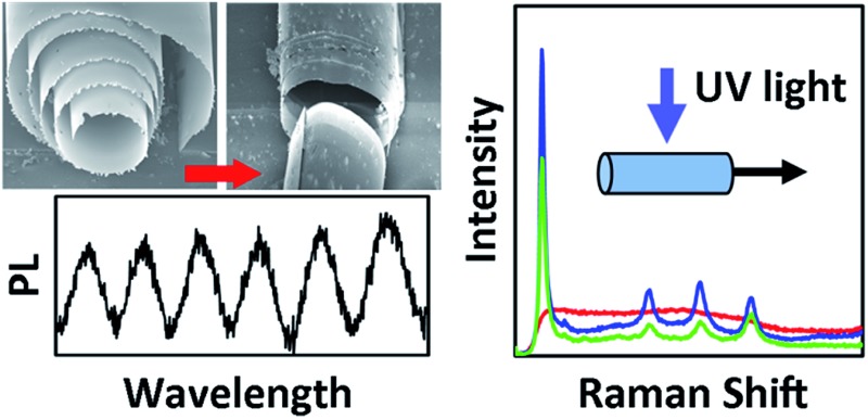
 The properties of TiO2 within rolled-up nanotechnology are explored. Micromotors and optical microresonators are presented as possible applications.
Abstract
Because of its unique properties, titania (TiO2) represents a promising candidate in a wide variety of research fields. In this paper, some of the properties and potential applications of titania within rolled-up nanotechnology are explored. It is shown how the structural and optical properties of rolled titania microtubes can be controlled by properly tuning the microfabrication parameters. The rolling up of titania films on different sacrificial layers and containing different shapes, achieving a control on the diameter of the fabricated titania microtubes, is presented. In order to obtain the more photoactive crystalline form of titania, one during-fabrication and two post-fabrication methods are demonstrated. Interesting applications in the fields of photocatalysis and photonics are suggested: the use of titania rolled-up microtubes as micromotors and optical microresonators is presented.
Introduction
In the last decades titania (TiO2) has received increasing attention due to its interesting properties including high chemical stability, high refractive index, optical transparency in the visible range, semiconducting behavior, photocatalytic activity, high photoelectric conversion efficiency, biocompatibility, and low costs.1 Titania exists in nature in three major crystalline phases: rutile, anatase, and brookite. Since rutile and anatase have properties of interest for multiple applications, they have been extensively characterized in the literature.2 Rutile is the most thermodynamically stable phase of titania, and is characterized by a higher refractive index than anatase. On the other hand, anatase is characterized by a stronger photocatalytic activity. Many different techniques such as sol–gel, sputtering, electron beam evaporation, atomic layer deposition, and chemical vapour deposition have been exploited for the preparation of titania structures.3,4 It is also well known that the properties of titania can be controlled by changing the processing techniques and parameters to fit desired applications.5,6 Because of its variety of properties, together with the possibility of tuning them, titania represents a promising candidate in a wide number of applications including solar cells,7 photocatalysis,8,9 sensing,10 hydrogen generation,11,12 energy storage,13,14 biomedical applications,15 and photonics.16,17
While titania has been widely explored in many different contexts, it has been only recently introduced to the world of rolled-up nanotechnology.18–20 The fabrication of rolled tubular microstructures21,22 has already been successfully applied to the development of catalytic micromotors, optofluidic sensors, microfluidic systems, micropumps, batteries, biophysics, as well as in the fields of electronics and photonics.23 While systems achieved by rolling nanomembranes composed of semiconductors, organic materials, metals, silicon oxides and magnetic materials have been extensively discussed,18 only recent works reported rolled titania structures and limited the discussion to their optical properties.19,20 Furthermore, only titania films deposited at room temperature on photoresist sacrificial layers have been considered. Moreover, the use of titania microtubes as photoactive material for self-propulsion of micromotors has not yet been reported, which might however be advantageous over other materials because only light and carboxylic acids acting as a chemical fuel are required for motion.
Here we present a systematic work on the fabrication and characterization of titania microtubes as an active material for different potential applications. We show how titania microtubes can be rolled up using different sacrificial layers and discuss the possibility of controlling not only geometrical characteristics but also the physical properties such as the crystalline phase. Self-propelled photoactive micromotors are demonstrated, highlighting the high photocatalytic activity of anatase tubes. Further potential applications are suggested including high refractive index tight rutile tubes as optical microresonators or, if the titania membrane is pre-patterned, the fabrication of diamond-like photonic crystals operating in the visible.24
Experimental
Microtube fabrication with photoresist sacrificial layer
Both silicon and glass slides were used as substrates for the fabrication of the microtubes. The substrates were sonicated in acetone and in isopropanol, then dried on a hotplate at 120 °C. The sacrificial layer was prepared by optical lithography. An adhesion promoter (TI Prime, MicroChemicals GmbH) was spin-coated on the samples at 3500 rpm for 20 s, and baked at 120 °C for 2 minutes. A positive photoresist (AR-P 3510, Allresist GmbH) was then deposited via spin-coating at 3500 rpm for 35 s, and baked at 90 °C for 3 minutes. The resulting thickness of the resist film was about 2 μm. Different patterns with size between 40 and 500 μm were transferred onto the samples by exposure to UV light with a mask aligner (MJB4, SÜSS MicroTec AG) with an exposure time of 9 s. The samples were developed by immersion into a 1 : 1 v/v solution of the developer (AR-300 35, Allresist GmbH) and DI water for 40 s, rinsed with DI water to remove any developer residues, and finally dried with nitrogen. The deposition of a TiO2 bilayer was carried out via electron beam evaporation (BOC Edwards FL400) using pure titanium pellets (Kurt J. Lesker Company) as a starting material, and an oxygen background (the pressure inside the chamber was 1.0 × 10⁻⁴ mbar). The two titania layers were deposited with a low (about 0.2–0.4 Å s–1) and a high (between 1.7 and 4 Å s–1) deposition rate, respectively. A 15° glancing angle was used during the deposition resulting in an uncovered window at the end of the patterned photoresist, allowing the subsequent removal of the sacrificial layer. The TiO2 membranes were rolled up into microtubes by immersion of the sample in dimethyl sulfoxide (DMSO) (VWR International S.A.S.), and then dried in a critical point dryer to avoid the collapse of the tubular structure caused by surface tension forces on the tubes during the solvent evaporation.
Microtube fabrication with SiO2 sacrificial layer
A 1 μm thick SiO2 sacrificial layer was deposited on a silicon substrate and patterned by photolithography using an AR-P 3510 mask. The desired pattern was transferred to the SiO2 film using a buffered HF solution with concentration 4% for 90 s. The photoresist mask was then removed with acetone. The titania angled deposition was performed as previously described, but in a Dreva Opt 400 e-beam system, which allowed the heating of the substrate. The TiO2 membranes were rolled into microtubes by immersion of the sample in buffered HF solution with a concentration of 0.4%, rinsed with DI water, and dried in a critical point dryer.
The samples which were tested as microresonators were coated with an additional 30 nm thick layer of TiO2 via atomic layer deposition (ALD) (FlexAL II, Oxford Instruments plc) at a temperature of 250 °C.
Structural and optical characterization
The structural and optical properties of titania deposited under different deposition conditions were investigated on single titania membranes deposited on silicon substrates under conditions described previously. Different deposition temperatures (room temperature, 300 °C and 500 °C) were investigated. The optical properties of the titania were studied also before and after dry and water annealing processes. In order to identify the titania phases obtained under the different deposition conditions, the deposited films were characterized by micro-Raman spectroscopy using a commercial Renishaw inVia Raman microscope. The Raman setup consists of a laser (HeCd at 442 nm and 17 mW) directed through a microscope to the sample after which the scattered light is collected and directed to a spectrometer with a 2400 blz mm–1 grating. The exposure time was 1 s, and each spectrum was collected with 500 accumulations. The refractive index of the titania films was estimated using ellipsometric measurements. An ellipsometer (J.A.Woolam Co. Inc. spectroscopic ellipsometer) was used to perform measurements at three different angles (65°, 70° and 75°) within the spectral range 350–800 nm. The estimation of the titania refractive index from the ellipsometric data was found to be challenging. The way the titania grows (characterized by grains oriented along the deposition direction), together with the coexistence of different titania phases, make it difficult to identify an appropriate model to fit the data. The results presented in this paper were achieved by fitting the refractive index of the titania layers using the first two terms of the Cauchy model, neglecting any absorbance.
The optical characterization of the rolled-up titania microtubes as 3D optical microcavities was carried out by micro-photoluminescence (PL) spectroscopy with the Renishaw inVia setup also used for the Raman characterization of the TiO2 membranes. The laser power was set to 8.5 mW and a 1200 blz mm–1 grating was used. The exposure time was 10 s, and the number of accumulations was 30.
Photoinduced motility experiments
1. Preparation of photoactive micromotors
The rolled-up TiO2 tubes were prepared as previously described and dried using a critical point dryer. In order to fabricate photocatalytically active tubes, annealing of the sample was performed in an oven at 400 °C for 3 h under air atmosphere.
2. Photocatalysis
The experiments were performed adding 100 μl of sodium acetate–acetic acid buffer (HAc 4.79 M/NaAc 0.21 M at pH = 3.6) on the glass substrate containing the sample and gently scratching with plastic tweezers to release the microtubes. A xenon light source LAXC-100 (Asahi Spectra USA Inc.) with 100 W power and equipped with an UVA filter (300–400 nm) was used to irradiate the sample with UVA light. The light source was placed at 20 mm from the sample, resulting in an irradiance power of 264.8 mW cm–2. The experiments were performed at room temperature (23 °C).
3. Analysis of videos
Videos were taken with a Phantom Miro eX2 high speed camera mounted to an inverted Axiotech microscope at a rate of 20 frames per second. The free software FiJi was used to track micromotor speed and trajectory and to edit videos and pictures.
Results and discussion
A schematic of the fabrication technique adopted in this work to obtain rolled-up titania microtubes is shown in Fig. 1. Although the photoresist represents the simplest choice of sacrificial layer, since common organic solvents (e.g. acetone, alcohols or dimethyl sulfoxide) can remove polymeric thin films over almost any inorganic materials with practically 100% selectivity, different materials (both metals like copper and oxides like SiO2 and GeOx) can also be used as a sacrificial layer for rolling titania tubes. An interesting advantage offered by sacrificial layers different from photoresist is the possibility of high temperature deposition or an additional patterning process of the titania membrane with a resist mask before the rolling up of the nanomembrane itself. However, a change in the sacrificial layer (and consequently in the chemistry used for its selective removal, which leads to the rolling of the membrane) can result in new constraints for the titania deposition. For example, if a silica sacrificial layer is employed the HF solution used to remove it may seriously damage the titania grown at room temperature. TiO2 deposited at temperatures higher than 300 °C is resistant to HF and hence allows a proper rolling up of the thin films. It is important to notice that the necessity of depositing titania at high temperature does not represent a drawback of the silica sacrificial layer, but a new opportunity which cannot be exploited using a photoresist pattern, since it would be damaged by such high temperatures.
Fig. 1. Schematic of the fabrication procedure. On the left upper corner, the substrate is shown (e.g. silicon or glass). The line above shows the fabrication procedure of titania tubes from a photoresist sacrificial layer. The photoresist (red) is patterned by optical lithography. A titania bilayer (light grey) is then grown via angled deposition. The sacrificial layer is finally removed with DMSO, resulting in the rolling of the titania nanomembrane. In the line below, the fabrication of titania tubes from a sacrificial layer different from photoresist is illustrated: both metals (for example Cu) and oxides (for example SiO2 or GeOx) have already been successfully used as sacrificial layers. The sacrificial layer (beige) is deposited on the substrate and patterned by photolithography using a photoresist mask. The desired pattern is then transferred to the film removing the uncovered material with a selective etchant, and the photoresist mask is removed afterwards with acetone. The titania bilayer is deposited on the sacrificial layer. The sacrificial layer is finally selectively etched, allowing the rolling of the titania nanomembrane.
In the following sections we discuss how the structural and optical properties of the microtubes can be controlled by tuning the deposition parameters (in particular the titania film thickness and the deposition temperature), by changing the rolling conditions, or with post-rolling treatments.
Dependence of the tube diameter on the thickness of the titania membrane
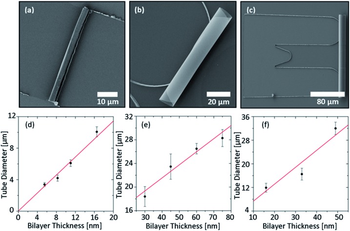
Tubular microstructures obtained by rolling up titania nanomembranes deposited via e-beam evaporation at room temperature on a photoresist sacrificial layer are reported in Fig. 2 and ESI Video S1†. Titania microtubes can be successfully rolled up starting from different shapes and sizes of the pattern, for example square, circular and U-shape masks (Fig. 2a–c). The square and circular patterns usually result in a higher yield (close to 100%) as previously reported for SiO2 (ref. 25) (see Fig. S1 in the ESI†). On the other hand, the U-shape offers interesting opportunities in the design of optical resonators, since it avoids light leakage where the center of the tube is lifted from the substrate and facilitates axial confinement of light.26,27 Each shape and size of the pattern requires an optimization process of the parameters (deposition rate, maximum thickness, and etching time) in order to achieve a good yield. Once an appropriate range of values for these parameters is identified, a good control of the tube diameter is possible by tuning the overall thickness of the titania bilayer. Fig. 2d–f shows the dependence of the tube diameter on the titania membrane thickness for the different patterns reported in Fig. 2a–c. For the square patterns, two titania layers were deposited at rates of 0.3 and 1.7 Å s–1, respectively. The thickness of the first layer was kept constant at 3 nm, while the thickness of the second layer was varied. With the circular pattern, a good rolling yield was instead achieved by depositing a 15 nm thick layer with a rate of 0.4 Å s–1 followed by a layer of various thicknesses at 3.8 Å s–1. Concerning the U-shape pattern, an 8 nm thick first layer was deposited with a rate of 0.2 Å s–1, while the second layer (with variable thickness) was grown with a rate of 2.1 Å s–1. In all three cases, an almost linear trend can be observed in the experimental data. The observed behavior allows a good prediction of the tube diameter based on the thickness of the titania membrane.
Fig. 2. (a–c) SEM images showing rolled-up TiO2 tubes using square, circular and U-shape patterns. In all the cases, titania membranes deposited at room temperature were rolled using a photoresist sacrificial layer. (d–f) Dependence of the tubes diameter on the titania membrane thickness for the different patterns presented in panels (a–c).
Dependence of the titania phase and refractive index on the deposition temperature
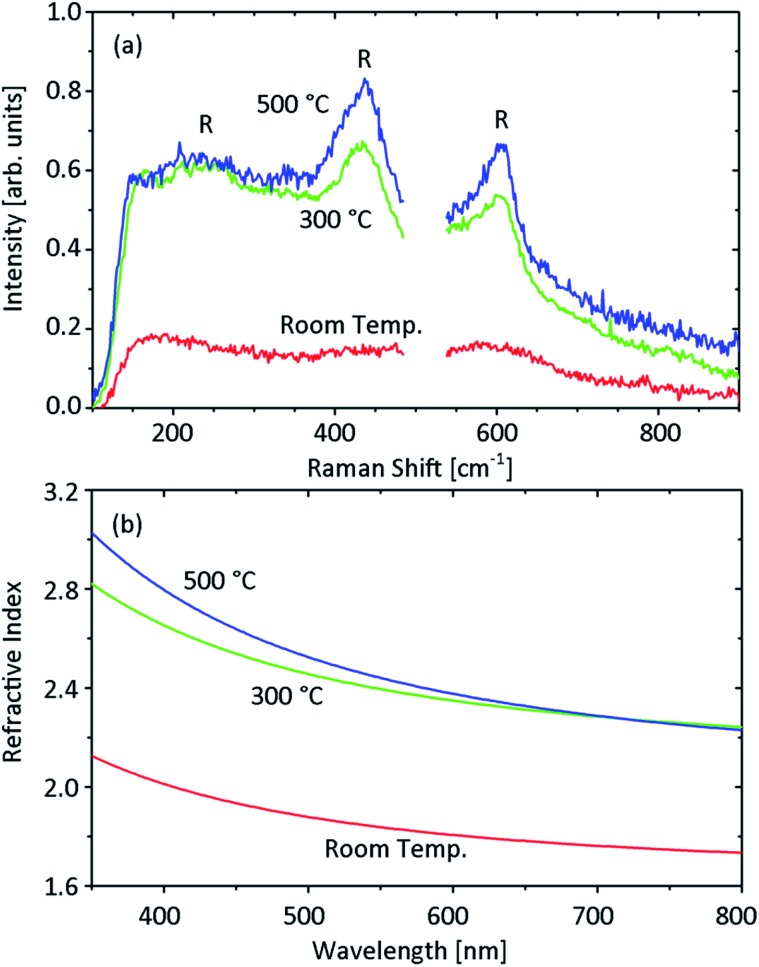
As previously mentioned, the silica sacrificial layer requires deposition of titania at high temperature. In order to understand the behavior of titania thin films deposited via e-beam evaporation on substrates heated to different temperatures, the structural and optical properties of single titania membranes grown on silicon substrates under different deposition conditions were investigated. It was observed that titania films grown at high temperature have grains visible by SEM, in contrast to the room temperature films in which no grains are visible, consistent with an amorphous phase. This behavior suggests a change from amorphous to polycrystalline in the grown TiO2 when the deposition temperature increases. This conclusion was confirmed by the Raman spectra of the investigated samples, reported in Fig. 3a. The film deposited at room temperature contains no detectable crystallinity, since no clear peaks were observed. At high deposition temperatures (both 300 °C and 500 °C), the main spectral features representing the signature of the rutile phase can be observed at 440 and 610 cm–1.28 The broader peak at about 220 cm–1 is also visible. While the Raman spectra do not allow quantification of the proportion between crystalline and amorphous titania present in the deposited film, a predominance of the crystalline phase in titania deposited at high temperature is consistent with its resistance to HF, which can instead easily damage the amorphous TiO2 films. The nature of the titania deposited at high temperatures is also indicated by the values of the films' refractive index. Fig. 3b reports the refractive index of the TiO2 layers obtained by ellipsometric measurements. The increase in the deposition temperature causes a significant shift to higher refractive indexes. The refractive index measured for titania films deposited at 300 °C and 500 °C is consistent with the results reported in literature for rutile.29 This makes titania deposited at high temperature extremely interesting for photonics applications, where success or failure relies heavily on the value of the refractive index. For example, this represents a crucial requirement for the development of 3D rolled photonic crystals operating at visible frequencies, which in one conceptualization require a refractive index of at least 2.3 to obtain a full photonic band gap.24 The possibility of increasing the titania refractive index via the deposition temperature should also improve the quality factor of rolled titania resonators due to a better confinement of the light. Since the refractive index does not strongly decrease when the deposition temperature is reduced from 500 °C to 300 °C, titania deposited at 300 °C was preferred, since it was proven to be easier to roll.
Fig. 3. Optical characterization of titania layers deposited at different temperatures (room temperature, 300 °C and 500 °C) on silicon substrates. The titania films were grown with angled deposition (glancing angle 15°), with a deposition rate of about 2 Å s–1 and pressure inside the chamber equal to 1.0 × 10⁻⁴ mbar. The film thickness is equal to 100 nm in the sample deposited at room temperature and about 200 nm for the samples deposited at high temperatures. (a) Raman spectra of the investigated titania samples. The spectrum measured for the bare silicon substrate has been subtracted from the spectra of the TiO2 samples. The main spectral features of rutile titania are indicated by a letter “R”. (b) Refractive index of the analysed titania films estimated by ellipsometric measurements.
Dependence of the tube tightness on the etching time
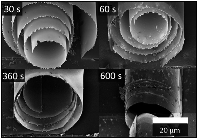
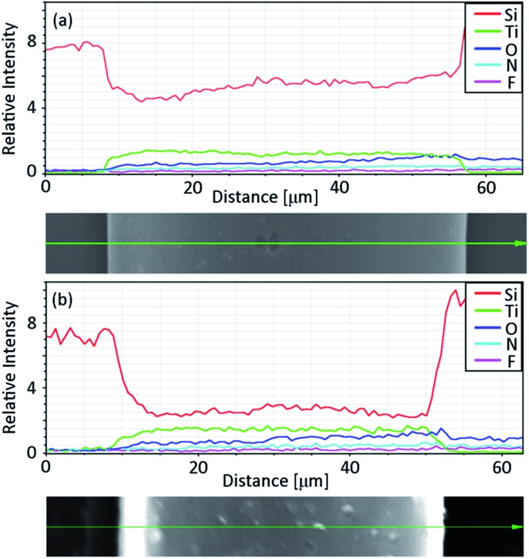
Together with the increase in the TiO2 refractive index due to the high temperature deposition, the silica sacrificial layer offers another interesting advantage of the possibility of controlling the tightness of the tubular microstructures. In some applications, this property might not be important or even desired: this can be the case for light harvesting or photocatalysis, where a larger surface to volume ratio represents an advantage. On the other hand, a good tube tightness is essential in photonic devices. For example, the presence of voids among the windings of the tube has been demonstrated to significantly decrease the quality of rolled resonators.27 Fig. 4 shows how the tightness of the microtube windings depends on the etching time of the SiO2 sacrificial layer in HF. For all the reported samples, a buffered HF solution with 0.4% concentration was used. In all the cases, the rolling up occurred after 20–25 s, but the samples were left in the etching solution for different times before rinsing them with DI water and drying them with a critical point dryer. Increasing the etching time, the rolled-up structure was observed to change from a spiral shape to a tubular one. A possible explanation for this behavior is the presence of residual SiO2 from the sacrificial layer attached to the underside of the TiO2, which in the case of shorter etching times would prevent a tight rolling. When the samples are immersed in the etchant solution for a longer time, the residual SiO2 is instead slowly removed from the TiO2 membrane, allowing a tighter rolling. EDX measurements performed on the tubes left in HF for 30 s and 10 minutes (see Fig. 5) support this explanation: while the titanium signal remains constant when the etching time increases, the signal related to the presence of silicon atoms is reduced to about one half.
Fig. 4. SEM images of TiO2 microtubes obtained with different etching times in HF (30–600 s). The TiO2 membranes were deposited at 300 °C.
Fig. 5. EDX line scans and SEM images of the samples with (a) the shortest (30 s) and (b) the longest (600 s) immersion times in buffered HF solution.
An unexpected effect of the longer immersion times in the HF solution is the increasing formation of small particles on the surface of the samples. The nature of the precipitate has not been studied further, but it is assumed that it is a by-product of the etching reaction. If the deposited thin films contain small amounts of amorphous titania, this would be dissolved in the buffered HF solution, forming ammonium hexafluoride (NH4)2TiF6. It was observed30 that this salt can be hydrolysed in an aqueous solutions of (NH4)2SiF6, HF and NH4, all of which are present in our system.
Control of the titania phase via post-rolling annealing
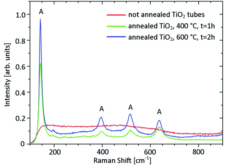
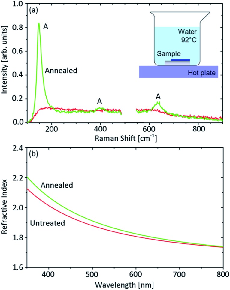
Another interesting opportunity offered by the TiO2 is the possibility of tuning its properties post-deposition. A first attempt for changing the titania phase from amorphous to crystalline consisted in a post-rolling dry annealing process. Annealing the tubes in an oven at temperatures up to 600 °C resulted in a change from amorphous to anatase of the rolled titania membrane, as measured by Raman spectroscopy (Fig. 6). The anatase phase of titania is of particular interest because of its photocatalytic activity. The possibility of exploiting dry-annealed tubes as micromotors is discussed in the following section. Unfortunately, this approach caused most of the TiO2 microtubes to distort or collapse. If highly symmetric tubes are needed, an alternative annealing process is required. In 2002, titanium sheets were oxidized and subsequently crystallized to anatase by soaking in hydrogen peroxide solution and hot water.31 An analogous approach to change the TiO2 phase post-deposition was reported by Y. Liao and coworkers:32 this consists of annealing amorphous titania samples grown at room temperature by immersion in hot water (92 °C) for about 20 hours. A schematic of the procedure is shown in the inset of Fig. 7a. Tubes annealed this way retained their tubular structure. In order to facilitate the optical characterization of the titania before and after the annealing process, the same test was performed on a titania membrane deposited on a silicon substrate. Fig. 7a shows the Raman spectra acquired before and after the hot water treatment. The water annealing increased the crystallinity of titania as evidenced by the anatase peak at about 150 cm–1 and the two weaker anatase features at about 400 and 650 cm–1. In Fig. 7b the TiO2 refractive index measured before and after the hot water procedure is also reported. The refractive index only slightly increases after the water treatment, and remains below the values expected for anatase (see for example ref. 33). This suggests the coexistence within the membrane of both amorphous and anatase titania. A low percentage of anatase titania present in the sample after the water annealing could explain why microtubes annealed using this procedure could not be successfully exploited as micromotors.
Fig. 6. Raman spectra measured on titania tubes annealed for 1 h at 400 °C (green line) and for 2 h at 600 °C (blue line). The Raman spectrum of a not annealed titania tube is also reported (red line). The tubes were obtained by rolling titania films deposited at room temperature with angled deposition (glancing angle 15°) on square (50 × 50 μm) photoresist patterns on a glass substrate. The main spectral features of anatase titania are indicated by a letter “A”.
Fig. 7. Optical characterization of a titania layer before and after the water annealing procedure, shown schematically in panel (a). The 100 nm thick titania film was grown at room temperature with angled deposition (glancing angle 15°), deposition rate of about 2 Å s–1 and pressure inside the chamber of 1.0 × 10⁻⁴ mbar. (a) Raman spectra of the investigated titania samples. The spectrum measured for the bare silicon substrate has been subtracted from the spectra of the TiO2 samples. The main spectral features of anatase titania are indicated by a letter “A”. (b) Refractive index of the analysed titania films estimated by ellipsometric measurements.
Potential application of photoactive TiO2 based microtubes: micromotors
Man-made micromotors are an exciting topic in the current multidisciplinary fields of material science. The challenge of producing functional materials that can convert chemical energy into translational motion is one of the current topics in nanotechnology.34–38 Most of the catalytically self-propelled micromotors reported to date use chemical fuels such as H2O2 or hydrazine.39–42 Here we aim to use other alternatives to the standard fuels employed so far. One way of achieving motion at the microscale is by using light as an external energy source, which will initiate chemical reactions in and around the micromotors. Alternatively, a couple of examples of recent photocatalytic motors can be found in the literature.43 This approach has been used by Sen and co-workers to power the motion of spherical particles.44
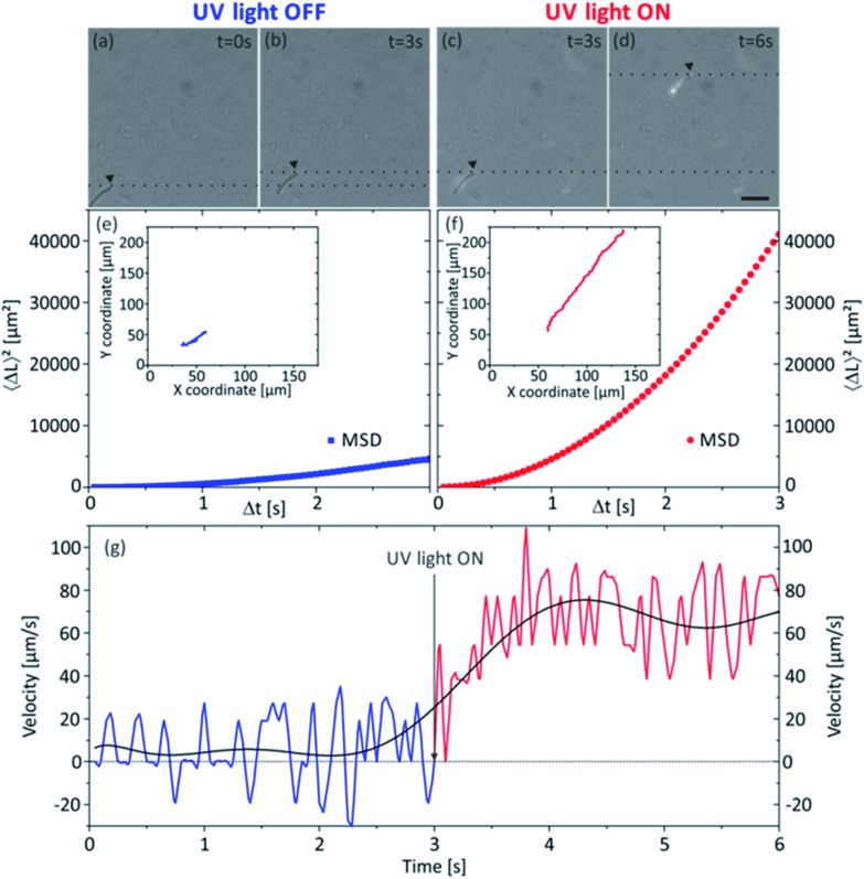
Here we present a photocatalytic TiO2 tubular micromotor (see Fig. 8 and ESI Video S2†), which was able to self-propel in buffered acetic acid–acetate aqueous solutions when the solution was irradiated with UV light (wavelengths 300–400 nm). The titania tube was annealed in air at 400 °C for 1 hour. While this procedure only resulted in a slight distortion of the tubular geometry, higher annealing temperatures were observed to strongly damage the morphology of the rolled-up structure. When the sample is not exposed to UV light, the annealed TiO2 microtube showed a slow motion (Fig. 8a, b and e) subjected to a combination of Brownian motion and convection currents in the buffer solution. Its instantaneous velocity oscillated from values around zero with positive and negative components with an average value of 15 μm s–1 (Fig. 8g), which is an evidence of the combination of these two factors mentioned above and highlighted by Howse et al. 45 As soon as we illuminated the aqueous medium with UV light, the photoactive microtube accelerated and started to navigate along its longitudinal axis in a straight trajectory (Fig. 8c, d and f) with velocities of about 60 μm s–1 (Fig. 8g) corresponding to 1.2 bdl s–1 (body lengths per second). It is important to note that we did not observe release of bubbles from the photoactive micromotor. The speed value is rather small compared with previous reports on bubble-propelled microjet engines.46,47 Additionally, not annealed titania microtubes were utilized to compare the photocatalytic motion of amorphous phase with anatase TiO2, but self-propulsion was not observed when amorphous titania microtubes were exposed to UV light, under the same experimental conditions. Hence, it is noteworthy that the post-rolling dry annealing process is necessary to achieve photocatalytic self-propulsion under these conditions.
Fig. 8. Analysis of the motion of a tubular TiO2 micromotor in sodium acetate–acetic acid buffer under UV light irradiation. (a)–(d) are sequential micrographs of a TiO2 tubular micromotor and its displacement in a time interval of 3 s when it is not irradiated with UV light and under UV light exposure. Scale bar 50 μm. Panels (e) and (f) show the computed mean-squared-displacement of a TiO2 tubular micromotor when it is not irradiated with UV light and under UV light exposure, respectively. Insets of (e) and (f) illustrate their tracked trajectories. Plot (g) illustrates the velocity of a tubular TiO2 micromotor over the course of a 6 s movie, calculated for Δt = 1/20 s. The curve is a polynomial fit used to guide the eye. The rapid fluctuations in velocity are expected, due to the small physical scale of the experiment and short measurement time intervals.
Even though the photocatalytic titania micromotors have the same tubular structure as catalytic microjets, the mechanism of motion might be completely different, and to elucidate the proper mechanism of motion one should refer to the discussion of diffusiophoretic motion as addressed earlier by Sen and co-workers.44 When titania tubes are illuminated with UV light, electron–hole pairs are photogenerated, which can react with oxygen and water in the medium generating highly oxidative species able to decompose organic molecules. The diffusiophoretic mechanism of motion is based on the diffusion of ions generated around the irradiated titania tube. In addition, ions will be asymmetrically generated inside and outside the tube, which will produce a fluid flow through the interior of the tube which pushes the tube forward. The ionic species generated outside the microtube will diffuse faster than those accumulated in the interior of the tubes. In this work, we used acetic acid as a sacrificial electron donor, as fuel for self-propulsion. The potential reactions that could be involved in the mechanism of the observed photoinduced motility are related to the so-called photo-Kolbe reactions48,49 for the photocatalytic decarboxylation of acetic acid (CH3COOH) in the presence of anatase under UV light. The main products of these reactions are methane (CH4) and carbon dioxide (CO2); however, ethane (C2H6), propane (C3H8) and hydrogen (H2) can also be produced in minor proportion.49 In addition, the photoreduction of dissolved oxygen50 in the buffer solution could also play a role in the generation of ions and radicals, which might be the driving force for the observed diffusiophoretic motion. Further understanding on the mechanism of motion needs to be addressed in a separate work.
This new type of tubular micromotor propels slower than the bubble-propelled catalytic microjets reported up to now.39,47,51 However, in this work, we use UV light and carboxylic acids as alternative fuel to H2O2 and we do not rely on expensive catalytic materials such as platinum nanomembranes. The use of light and organic compounds as fuel holds considerable promise for the design of new sources of motion at the microscale. This new example of a photoactive tubular micromotor could open the possibility to avoid the use of fuels like H2O2 or hydrazine without using the body of the motor as a fuel itself,52–54 in order to self-propel micro- and nanomotors and for micropumping systems.
Potential application of rutile TiO2 microtubes: microresonators
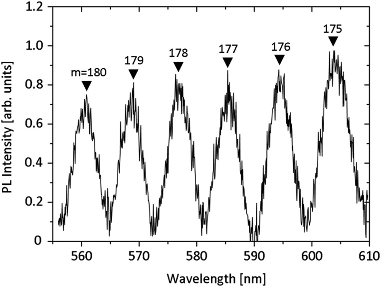
Optical microresonators have wide-ranging applications in myriad technologies including optical circuitry, quantum information and computing, lasing, solar technology, and sensing. Of the resonator geometries explored, rolled-up microtubes have the benefits of being fabricated on-chip, being thin-walled, and hollow. Having light confined by a thin walled hollow resonator is advantageous because it increases the interaction volume between the extending evanescent wave and the environment for sensing applications. It has recently been shown that rolled-up TiO2 microtubes deposited at room temperature act as optical resonators and support optical resonance modes from the visible to the infrared range.19,20 The performance of the resonators can potentially be enhanced when the refractive index of the tube wall material is increased, since this improves the light confinement and thus the achievable Q-factor. Fig. 9 shows how tightly rolled titania microtubes with a high refractive index can work as optical microresonators in the visible range. The samples were prepared as described above. Initially the photoluminescence (PL) from the as-prepared titania was too low to clearly observe optical modes, likely due to very low oxygen vacancies and defects. However, it has been observed that TiO2 deposited via atomic layer deposition (ALD) results in slightly more intense PL. Therefore, after the critical point drying, the tubes were additionally coated with a 30 nm thick layer of TiO2 via ALD. The PL is still weak, however, further improvements should be made in the future through the inclusion of other light emitters such as quantum dots or ALD of TiO2 under different conditions, for example at low temperatures. QDs can be embedded in the windings of the tube during the roll-up process, or drop-cast onto the surface of the resonator after rolling. The precise source of PL in ALD TiO2 is a topic of future study.
Fig. 9. Photoluminescence spectrum of a TiO2 microtube deposited at high temperatures and rolled from a circular pattern. The resonator was coated via ALD after drying. “m” indicates the mode number.
Conclusions
Titania is an interesting material due to its high refractive index while remaining transparent in the visible, its versatility, and its photocatalytic activity. The combination of this material with rolled-up nanotechnology presents many interesting opportunities for novel applications. Control over the structural and optical properties of rolled-up titania microtubes has been achieved by means of a proper tuning of the fabrication parameters. We have demonstrated rolled-up titania as a functional material for applications such as self-propelled micromotors which can pave the way for motion of rolled-up micromotors in alternative fuels controlled by light. Furthermore, applications are suggested in the field of photonics. The quality of confinement of light in microresonators depends strongly on the refractive index of the material. The introduction of high refractive index titania to rolled-up microresonators could improve their performance. Moreover, some proposed photonic applications, such as rolled-up 3D photonic crystals, have a critical refractive index threshold which titania can achieve.
Acknowledgments
The research leading to these results has received funding from the European Research Council under the European Union's Seventh Framework Programme (FP7/2007-2013)/ERC grant agreement no. [311529]. M. R. Jorgensen gratefully acknowledges support from the Alexander von Humboldt foundation. The authors thank R. Engelhard for technical support and S. M. Harazim, S. Nestler, S. Seifert and M. Bauer for clean room support. The authors also acknowledge H. Shakur Shahabi (Institute for Complex Materials, IFW Dresden) for EDX measurements.
Footnotes
References
- Kamat P. V. J. Phys. Chem. C. 2012;116:11849. [Google Scholar]
- Hanaor D. A. H., Sorrell C. C. J. Mater. Sci. 2011;46:855. [Google Scholar]
- Chen D. H., Caruso R. A. Adv. Funct. Mater. 2013;23:1356. [Google Scholar]
- Yu A., Lu G. Q. M., Drennan J., Gentle I. R. Adv. Funct. Mater. 2007;17:2600. [Google Scholar]
- Chen X., Mao S. S. Chem. Rev. 2007;107:2891. doi: 10.1021/cr0500535. [DOI] [PubMed] [Google Scholar]
- Vivero-Escoto J. L., Chiang Y. D., Wu K. C.-W., Yamauchi Y. Sci. Technol. Adv. Mater. 2012;13:013003. doi: 10.1088/1468-6996/13/1/013003. [DOI] [PMC free article] [PubMed] [Google Scholar]
- Yan J. F., Zhou F. J. Mater. Chem. 2011;21:9406. [Google Scholar]
- Pelaez M., Nolan N. T., Pillai S. C., Seery M. K., Falaras P., Kontos A. G., Dunlop P. S. M., Hamilton J. W. J., Byrne J. A., O'Shea K., Entezari M. H., Dionysiou D. D. Appl. Catal., B. 2012;125:331. [Google Scholar]
- Oveisi H., Rahighi S., Jiang X., Nemoto Y., Beitollahi A., Wakatsuki S., Yamauchi Y. Chem.–Asian J. 2010;5:1978. doi: 10.1002/asia.201000351. [DOI] [PubMed] [Google Scholar]
- Qiu J. X., Zhang S. Q., Zhao H. J. Sens. Actuators, B. 2011;160:875. [Google Scholar]
- Khan S. U. M., Al-Shahry M., Ingler W. B. Science. 2002;297:2243. doi: 10.1126/science.1075035. [DOI] [PubMed] [Google Scholar]
- Murdoch M., Waterhouse G. I. N., Nadeem M. A., Metson J. B., Keane M. A., Howe R. F., Llorca J., Idriss H. Nat. Chem. 2011;3:489. doi: 10.1038/nchem.1048. [DOI] [PubMed] [Google Scholar]
- Froschl T., Hormann U., Kubiak P., Kucerova G., Pfanzelt M., Weiss C. K., Behm R. J., Husing N., Kaiser U., Landfester K., Wohlfahrt-Mehrens M. Chem. Soc. Rev. 2012;41:5313. doi: 10.1039/c2cs35013k. [DOI] [PubMed] [Google Scholar]
- Liu R., Sen A. J. Am. Chem. Soc. 2012;134:17505. doi: 10.1021/ja211932b. [DOI] [PubMed] [Google Scholar]
- Popat K. C., Eltgroth M., La Tempa T. J., Grimes C. A., Desai T. A. Small. 2007;3:1878. doi: 10.1002/smll.200700412. [DOI] [PubMed] [Google Scholar]
- Bradley J. D. B., Evans C. C., Choy J. T., Reshef O., Deotare P. B., Parsy F., Phillips K. C., Loncar M., Mazur E. Opt. Express. 2012;20:23821. doi: 10.1364/OE.20.023821. [DOI] [PubMed] [Google Scholar]
- Jorgensen M. R., Galusha J. W., Bartl M. H. Phys. Rev. Lett. 2011;107:143902. doi: 10.1103/PhysRevLett.107.143902. [DOI] [PubMed] [Google Scholar]
- Mei Y. F., Huang G. S., Solovev A. A., Urena E. B., Moench I., Ding F., Reindl T., Fu R. K. Y., Chu P. K., Schmidt O. G. Adv. Mater. 2008;20:4085. [Google Scholar]
- Wang J., Zhan T., Huang G., Cui X., Hu X., Mei Y. F. Opt. Express. 2012;20:18555. doi: 10.1364/OE.20.018555. [DOI] [PubMed] [Google Scholar]
- Madani A., Böttner S., Jorgensen M. R., Schmidt O. G. Opt. Lett. 2014;39:189. doi: 10.1364/OL.39.000189. [DOI] [PubMed] [Google Scholar]
- Prinz V. Y., Seleznev V. A., Gutakovsky A. K., Chehovskiy A. V., Preobrazhenskii V. V., Putyato M. A., Gavrilova T. A. Physica E. 2000;6:828. [Google Scholar]
- Schmidt O. G., Eberl K. Nature. 2001;410:168. doi: 10.1038/35065525. [DOI] [PubMed] [Google Scholar]
- Smith E. J., Xi W., Makarov D., Mönch I., Harazim S., Bolaños Quiñones V. A., Schmidt C. K., Mei Y., Sanchez S., Schmidt O. G. Lab Chip. 2012;12:1917. doi: 10.1039/c2lc21175k. [DOI] [PubMed] [Google Scholar]
- Jorgensen M. R., Giudicatti S., Schmidt O. G. Phys. Rev. A: At., Mol., Opt. Phys. 2013;87:041803. [Google Scholar]
- Harazim S. M., Xi W., Schmidt C. K., Sanchez S., Schmidt O. G. J. Mater. Chem. 2012;22:2878. [Google Scholar]
- Strelow C., Schultz C. M., Rehberg H., Sauer M., Welsch H., Stemmann A., Heyn C., Heitmann D., Kipp T. Phys. Rev. B: Condens. Matter Mater. Phys. 2012;85:155329. [Google Scholar]
- Böttner S., Li S. L., Trommer J., Kiravittaya S., Schmidt O. G. Opt. Lett. 2012;37:5136. doi: 10.1364/OL.37.005136. [DOI] [PubMed] [Google Scholar]
- Mazza T., Barborini E., Piseri P., Milani P., Cattaneo D., Bassi A. L., Bottani C. E., Ducati C. Phys. Rev. B: Condens. Matter Mater. Phys. 2007;75:045416. [Google Scholar]
- Devore J. R. J. Opt. Soc. Am. 1951;41:416. [Google Scholar]
- Bakeeva N. G., Gordienko P. S., Parshina E. V. Russ. J. Gen. Chem. 2010;80:223. [Google Scholar]
- Wu J. M., Hayakawa S., Tsuru K., Osaka A. J. Ceram. Soc. Jpn. 2002;110:78. [Google Scholar]
- Liao Y. L., Que W. X., Zhong P., Zhang J., He Y. C. ACS Appl. Mater. Interfaces. 2011;3:2800. doi: 10.1021/am200685s. [DOI] [PubMed] [Google Scholar]
- Vishwas M., Rao K. N., Chakradhar R. P. S. Spectrochim. Acta, Part A. 2012;99:33. doi: 10.1016/j.saa.2012.09.009. [DOI] [PubMed] [Google Scholar]
- Mallouk T. E., Sen A. Sci. Am. 2009;300:72. doi: 10.1038/scientificamerican0509-72. [DOI] [PubMed] [Google Scholar]
- Sanchez S., Pumera M. Chem.–Asian J. 2009;4:1402. doi: 10.1002/asia.200900143. [DOI] [PubMed] [Google Scholar]
- Wang J. ACS Nano. 2009;3:4. doi: 10.1021/nn900113x. [DOI] [PMC free article] [PubMed] [Google Scholar]
- Fournier-Bidoz S., Arsenault A. C., Manners I., Ozin G. A. Chem. Commun. 2005:441. doi: 10.1039/b414896g. [DOI] [PubMed] [Google Scholar]
- Mei Y. F., Solovev A. A., Sanchez S., Schmidt O. G. Chem. Soc. Rev. 2011;40:2109. doi: 10.1039/c0cs00078g. [DOI] [PubMed] [Google Scholar]
- Sanchez S., Ananth A. N., Fomin V. M., Viehrig M., Schmidt O. G. J. Am. Chem. Soc. 2011;133:14860. doi: 10.1021/ja205012j. [DOI] [PubMed] [Google Scholar]
- Wang J., Gao W. ACS Nano. 2012;6:5745. doi: 10.1021/nn3028997. [DOI] [PubMed] [Google Scholar]
- Solovev A. A., Xi W., Gracias D. H., Harazim S. M., Deneke C., Sanchez S., Schmidt O. G. ACS Nano. 2012;6:1751. doi: 10.1021/nn204762w. [DOI] [PubMed] [Google Scholar]
- Wilson D. A., Nolte R. J. M., van Hest J. C. M. Nat. Chem. 2012;4:268. doi: 10.1038/nchem.1281. [DOI] [PubMed] [Google Scholar]
- Sen A., Ibele M., Hong Y., Velegol D. Faraday Discuss. 2009;143:15. doi: 10.1039/b900971j. [DOI] [PubMed] [Google Scholar]
- Hong Y. Y., Diaz M., Cordova-Figueroa U. M., Sen A. Adv. Funct. Mater. 2010;20:1568. [Google Scholar]
- Dunderdale G., Ebbens S., Fairclough P., Howse J. Langmuir. 2012;28:10997. doi: 10.1021/la301370y. [DOI] [PubMed] [Google Scholar]
- Solovev A. A., Sanchez S., Pumera M., Mei Y. F., Schmidt O. G. Adv. Funct. Mater. 2010;20:2430. [Google Scholar]
- Solovev A. A., Mei Y., Bermúdez Ureña E., Huang G., Schmidt O. G. Small. 2009;5:1688. doi: 10.1002/smll.200900021. [DOI] [PubMed] [Google Scholar]
- Kraeutler B., Bard A. J. J. Am. Chem. Soc. 1978;100:2239. [Google Scholar]
- Mozia S., Heciak A., Morawski A. W. Catal. Today. 2011;161:189. [Google Scholar]
- Kumar S. G., Devi L. G. J. Phys. Chem. A. 2011;115:13211. doi: 10.1021/jp204364a. [DOI] [PubMed] [Google Scholar]
- Gao W., Sattayasamitsathit S., Wang J. Chem, Rec. 2012;12:224. doi: 10.1002/tcr.201100031. [DOI] [PubMed] [Google Scholar]
- Gao W., Pei A., Wang J. ACS Nano. 2012;6:8432. doi: 10.1021/nn303309z. [DOI] [PubMed] [Google Scholar]
- Mou F., Chen C., Ma H., Yin Y., Wu Q., Guan J. Angew. Chem., Int. Ed. 2013;52:7208. doi: 10.1002/anie.201300913. [DOI] [PubMed] [Google Scholar]
- Gao W., Feng X., Pei A., Gu Y., Li J., Wang J. Nanoscale. 2013;5:4696. doi: 10.1039/c3nr01458d. [DOI] [PubMed] [Google Scholar]
Associated Data
This section collects any data citations, data availability statements, or supplementary materials included in this article.


