Abstract
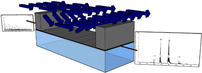
Salt removal is a prerequisite for electrospray ionization mass spectrometry (ESI-MS) analysis of biological samples. Rapid desalting and a low volume connection to an electrospray tip are required for time-resolved measurements. We have developed a microfabricated desalting device that meets both requirements, thus providing the foundational technology piece for transient ESI-MS measurements of complex biological liquid specimens. In the microfabricated device, the sample flows in a channel separated from a higher flow rate, salt-free counter solution by a monolithically integrated nanoporous alumina membrane, which can support pressure differences between the flow channels of over 600 kPa. Salt is removed by exploiting the large difference in diffusivities between salts and the typical ESI-MS target bioanalytes, e.g., peptides and proteins. We demonstrate the capability to remove 95% of salt from a sample solution in ∼1 s while retaining sufficiently high concentration of a relatively low molecular weight protein, cytochrome-c, for ESI-MS detection.
Electrospray ionization mass spectrometry (ESI-MS) has become a powerful and widely used tool for biological research and, as a result, was recognized with the Nobel Prize for Chemistry in 2002.1 In ESI, electrohydrodynamic forces produce a highly charged aerosol from a liquid sample.2 The resulting soft ionization of dissolved molecules within the droplets preserves many important biochemical details, and multiple charging of analytes allows detection of large molecules that could otherwise be outside of the range of the mass spectrometer.3 A difficulty in application of ESI-MS to biological samples is the negative impact of salts on the method,4 and salt removal is therefore an important part of ESI-MS workflows.5 Off-line desalting is predominantly via solid phase extraction (SPE).6 In online salt removal, which brings advantages such as increased analysis speed, repeatability, and decreased minimum sample size, a desalting device is integrated into the flowpath leading to the ESI capillary.7,8 Online salt removal can be via differential diffusion (dialysis), size exclusion (ultrafiltration), and differential surface chemical affinities (SPE). The most straightforward online desalting method is simply an online approach to SPE using switching valves to transition from sample concentration/desalting to elution. The disadvantages of online SPE for some applications include increased process time and change from water to an organic solvent. Thus, there has been interest in developing non-SPE online desalting approaches.
Most non-SPE online salt removal approaches have been modifications of the approach pioneered by the Smith group using a cellulose dialysis tube.9,10 In these approaches, the sample flows through the porous walled tube while a dialysis buffer solution flows outside of the tube, and salt diffuses from the inner to outer flowstream while higher molecular weight analytes are retained in the inner stream, both due to the filtering property of the membrane and the lesser mobility of larger molecules as compared to the salt ions. These devices are hand assembled, with the inlet and outlet sample tubing glued into the dialysis tube. Improvements of online dialysis devices have included (i) reduction in dead volume and therefore expansion to lower flow rate, (ii) size reduction, i.e., reduction in sample channel transverse dimension, and (iii) efforts toward microfabrication of dialysis devices. Dead volume reduction enables reduced flow rates and sample sizes, which allows online connection to nano-ESI-MS and thus improved sensitivity.11,12 Size minimization reduces transport time scales and therefore reduces the required sample transit time: such mass transport length scale reductions for tube-in-tube devices have improved performance by changing online desalting times from ∼20 min to ∼1 min.10,13
Microfabrication is a clear route to size reduction, but the geometry of the tube-in-tube dialysis approach is not easily incorporated into the planar layout of microfabricated devices. Therefore, the tube-in-tube approach was abstracted to a sandwich approach,14,15 with a flat cellulose membrane placed between microchannels on opposing chips. This approach, which can be seen as the first step toward a fully microfabricated lab-on-a-chip device, reduced desalting times to as low as 12 s. Microfabrication of the separation membrane as an integral part of the chip-scale device is seen as an important step toward incorporation of online membrane based desalting for ESI-MS in batch fabricated devices, and Song et al. reported the first planar, microfabricated dialysis devices with integral membranes, using nanoporous polymer membranes fabricated on the device.16 The demonstrated performance was not better than that of the best cellulose membrane based devices, with desalting times of ∼1 min. The most likely reason for the failure of their microfabricated device to realize a performance improvement is that the limiting mass transfer resistance is in the membrane, not the flow streams, and so size reduction of the sample channel does not reduce required residence time. This is highlighted by the approach that has the best demonstrated performance, with less than 1 s required for desalting demonstrated in a laminar coflow microfluidic device.17 This device eliminates the use of a membrane completely and carefully brings the sample and buffer streams together without mixing, having them coflow in the same direction, and then separates the two streams. The main limitation to this membraneless laminar coflow approach is that the buffer and sample stream must be in mechanical equilibrium, i.e., at the same pressure at each streamwise position, which is a difficult-to-meet constraint. In this letter, we report the demonstration of a microfabricated, monolithic device, which not only achieves the time response and separation effectiveness matching those of the membraneless approach but importantly also enables desalting without limitation on the sample pressure. This flexibility in the choice of sample pressure provides a route for downstream integration with a large set of classical and emerging ionization methods operating over a broad range of pressures, including ambient and subambient, coupled to active and passive sampling methods.18−23
We have developed a planar microfabricated device that meets the requirements for online chip based dialytic salt removal for ambient ESI-MS with ∼1 s transit time, through monolithic incorporation of an ultrathin integral membrane made of porous alumina (Figure 1). Approaches to integration of porous alumina membranes into MEMS devices have been developed over the past decade,24 and microfabrication of a freestanding nanoporous membrane of less than 10 μm thickness as one wall of microfabricated sample channel was accomplished by Narayanan et al.25 Porous alumina membranes have remarkably well ordered, straight, uniform, high density pores, and thus, provide for a given thickness, a minimal resistance to mass transfer. The membranes in the device described in this work restrict transmembrane flow sufficiently such that mass transport across the membrane is dominated by diffusion. This conclusion is based both upon an experimentally validated model for salt removal in the device that includes transmembrane flow (Supporting Information) and successful application of the device to desalting for ESI-MS analysis. The membranes, despite being ultrathin, are mechanically robust enough to support pressure differences in excess of 600 kPa. Because the sample channel is patterned in SU-8, addition of the SU-8 based nib-type nanoelectrospray tip as developed by Le Gac et al.26 for monolithically batch microfabricated online dialysis ESI devices is straightforward. The microfabricated device consists of a sample channel that has a rectangular cross section with a height of 6 μm and a width of 100 μm (Figure 1). The channel is defined on the lateral walls by SU-8 photoresist. The dimensions of the channel were chosen as a compromise between minimizing mass transfer resistance within the sample channel, which is proportional to channel height, and minimizing clogs. An ∼5 μm thick porous anodic alumina membrane that provides transport access to a buffer fluid outside of the channel constitutes the top wall. The thickness of the membrane is based on ensuring sufficient mechanical strength while also minimizing mass transport resistance, which is proportional to membrane thickness. The bottom wall is a borosilicate glass substrate that allows visibility into the channel to monitor flow and to detect bubbles and clogging during device operation. The high aspect ratio etched orifices in the silicon substrate provide an inlet and an outlet from the sample channel into fluidic interfaces, which are suitable for integration with the sampling probe tip (at the inlet) and the ion source (at the outlet). Details of microfabrication and packaging are provided in the Supporting Information.
Figure 1.
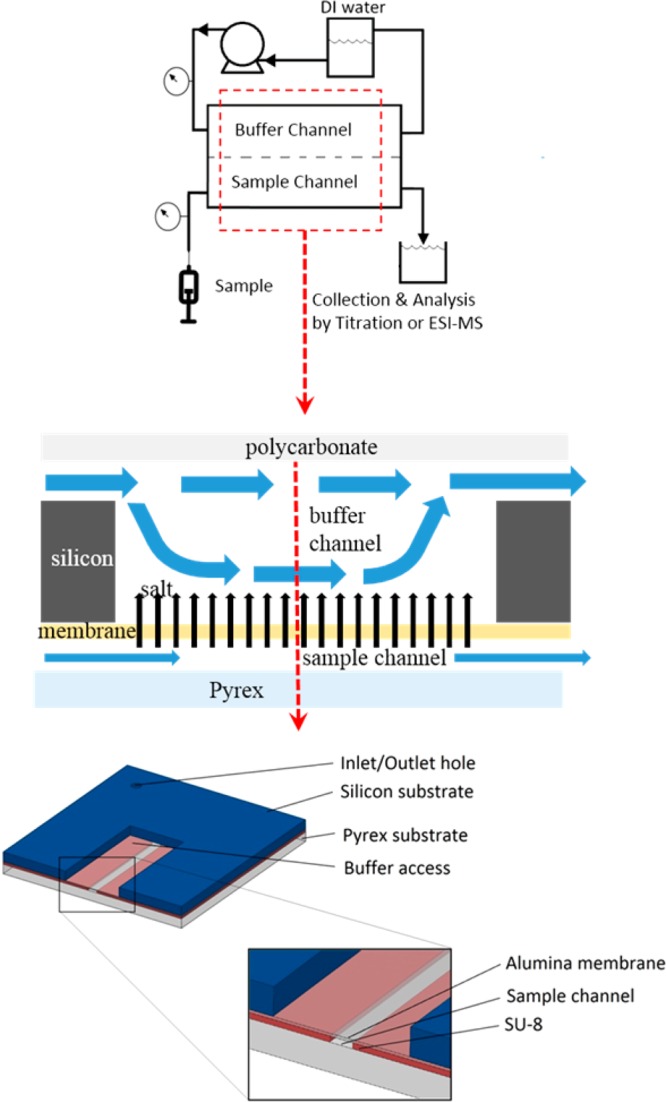
Experimental setup (top) and device schematic (middle) with the microfabricated device sectioned view (bottom).
Experimental characterization of the microfabricated salt removal devices includes two assessments: (1) the amount of salt removed is determined and (2) resulting improvement in the mass spectrum. The effectiveness of the microfabricated device at removing salt was tested by forcing a salt solution (300 mM KCl in DI water, where the concentration is chosen to ensure detection of salt after dialysis) through the sample channel at flow rates ranging from 30 to 150 μL/h and DI water through the buffer channel at a flow rate of 50 mL/h. The salt solution was collected at the sample outlet, and chloride concentration of the collected sample is measured using argentometric titration (Mohr method).27 The change in chloride ion concentration in the solution due to treatment with the device is an indication of the effectiveness of the device at removing salt. Experimental results are plotted in Figure 2 as removal percent effectiveness, 100% (1 – Cout/Cin) where Cout and Cin are average molar concentrations at the sample channel outlet and inlet, respectively. Also plotted in Figure 2 is the curve of predicted effectiveness from a mass transfer model of the device (Supporting Information), which is found to accurately predict device performance.
Figure 2.
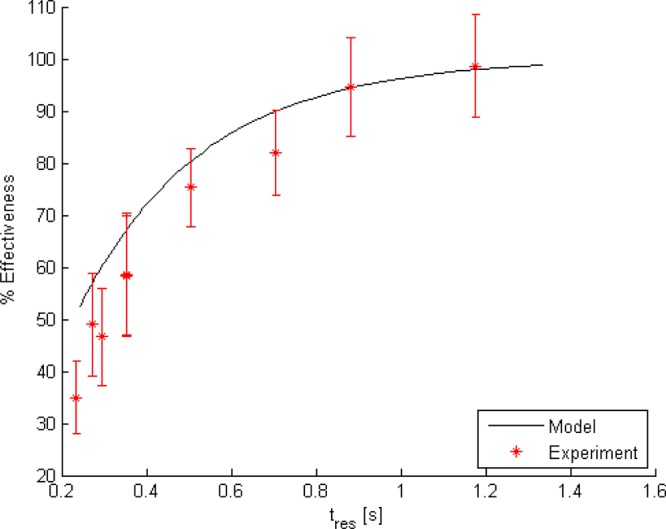
Plot of experimentally determined salt removal effectiveness vs sample residence time (red). Error bars are based on the titration method error determined via blinded experiments with known concentration samples. The black curve depicts the prediction obtained from solving the model equations numerically in MATLAB.
To facilitate analysis and understanding of the desalting quantification experimental results, and to serve as a tool for future device design and operational guidance, we have developed a simple model that captures all relevant dominant physics of the microfabricated desalting device (see the Supporting Information). The two-dimensional steady state model is based on the following assumptions and simplifications: (1) pressure drop in the sample channel can be well approximated using a unidirectional (parallel) laminar fully developed flow model; (2) salt concentration in the buffer solution far from the membrane is approximately zero; (3) mass transfer of the salt can be well described using a Fickian diffusion model with an effective binary diffusion coefficient; (4) properties (e.g., density, viscosity) of the sample liquid are uniform; and (5) transmembrane flow rates are low enough that the Peclet number for mass transfer remains small in the membrane and mass transfer across the membrane is dominated by diffusion while (6) sample channel flow rates remain sufficiently large that the mass transport in the sample flow direction is dominated by advection.
The highest residence time in Figure 2, 1.2 s, which occurs at the lowest flow rate, 30 μL/h (8.33 nL/s), corresponds to flow rates approaching, but greater than, those that produce the benefits of nano-ESI-MS.28 Lower residence times (higher flow rates) are included primarily for the purpose of model validation. Inspection of Figure 2 indicates that the model is impressively accurate considering that it is based strictly on first-principles without using any “fitting” parameters. The only experimentally derived input is the membrane hydraulic permeability, which is an intrinsic property of the membrane itself and was determined from independent characterization experiments. Importantly, in determining the membrane hydraulic permeability (see the Supporting Information) the membranes were subjected to differential pressures exceeding 600 kPa without experiencing failure, indicating their mechanical robustness. Having demonstrated the predictive capability of the model one can use it to obtain insight into device behavior. A critical observation is that the mass transfer resistance in the buffer is larger than both the mass transfer resistance in the membrane and the mass transfer resistance in the sample channel. Thus, the membrane does not significantly reduce mass transfer performance below that achievable in a device without a membrane, and performance improvements should focus on reduction of buffer mass transfer resistance. Furthermore, the transmembrane velocity never becomes large enough to significantly alter the mass transfer resistance through the membrane, as can be seen by estimating the relative importance of advection to diffusion given by the mass transfer Peclet number, which remains below 10–2 for the range of pressures and flow rates for which we tested the device.
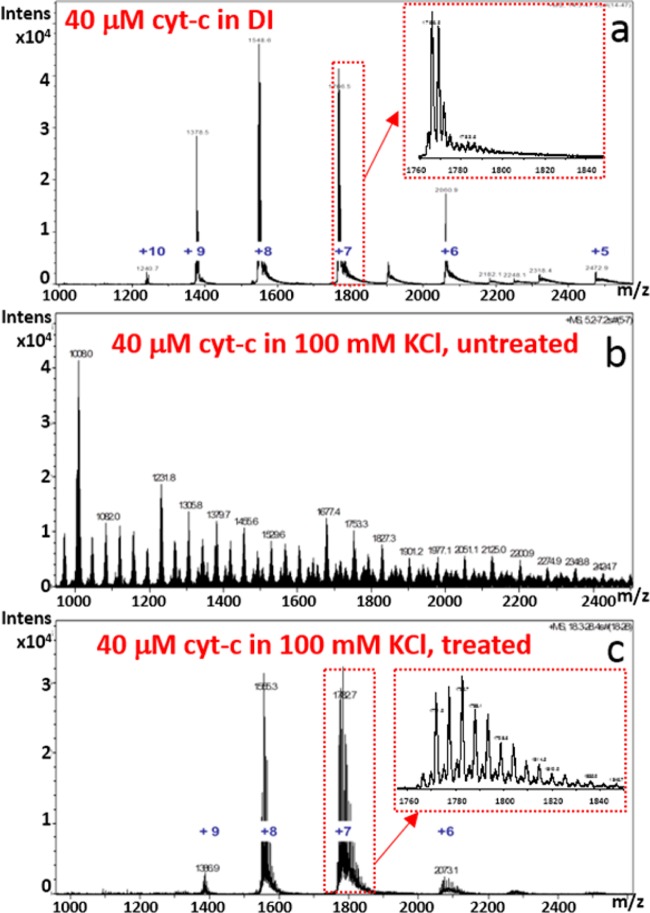
The device’s ability to enable the identification of an analyte in a solution with high salt content by nano-ESI-MS was also demonstrated. Solutions used for this assessment were (1) 40 μM cytochrome-c in DI water, (2) 40 μM cytochrome-c in 100 mM KCl, untreated, and (3) 40 μM cytochrome-c in 100 mM KCl, treated by flowing it through the sample channel of a microfabricated desalting device at 30 μL/h. Each sample was subjected to nano-ESI-MS analysis on a Bruker MicroTOF mass spectrometer under identical spray conditions, and the resulting mass spectra (1 s average) are displayed in Figure 3.
Figure 3.
Mass spectra from experiments to demonstrate utility of salt removal device for positive mode nano-ESI MS: (a) control sample with 40 μM cytochrome-c in DI water; (b) untreated sample, 40 μM cytochrome-c in 100 mM KCl; and, (c) treated sample, 40 μM cytochrome-c in 100 mM KCl under conditions corresponding to 1.3 s residence time in Figure 2. The charge states of cytochrome-c are labeled in blue in parts a and c. The source of the unlabeled peaks evident between the 5+ and 6+ charge states, and between the 6+ and 7+ charge states has not been identified.
The sample whose spectrum is displaced in Figure 3a serves as a control, as this is the spectrum that is obtained when no KCl is added and no cytochrome-c is lost. Figure 3b, which is also a control, demonstrates quite well the problem with salt. With 100 mM KCl present, all evidence of cytochrome-c is lost from the spectrum. This is in spite of the fact that nano-ESI-MS is much more salt tolerant than conventional ESI-MS.4 After passage of the salty sample through the salt removal device at 30 μL/h, which the model and experiment show will lower the salt concentration to ∼5 mM, most, but not all, of the peaks associated with cytochrome-c are visible again in Figure 3c. There are several possible explanations for the differences between the spectra in parts a and c of Figure 3. First, and perhaps most likely, 5 mM is still a relatively high salt concentration for nano-ESI-MS, so salt removal may not have been sufficient. That salt is still impacting the spectral quality as evident by comparing the narrow m/z range insets in the spectra. Second, salt removal efficiency was quantified and model accuracy was verified measuring the anion (Cl–) concentration, but the cation (K+) is most responsible for degrading the spectrum in the positive mode nano-ESI used here. Therefore, if the device behaves differently for cation removal then it may not be as effective as predicted for positive mode nano-ESI-MS experiments. This possibility seems unlikely for several reasons. When KCl is the only salt and there are no other sources of charge, then potassium cation and chloride anion concentrations will be equal everywhere that electroneutrality holds outside of any Debye layer at the solid/liquid interfaces. Because of the large disparity between the Debye length, ∼1 nm29 for 300 mM KCl in water and the pore diameter, ∼50 nm, and because both ions have nearly identical diffusion coefficients in water, the use of chloride ion concentration as a proxy for potassium ion concentration is justified, especially in light of the robust and accurate titration method available for chloride determination. Finally, it is important to consider the possibility that a significant quantity of analyte was lost during the dialysis. This possibility can be evaluated using the model by replacing the diffusion coefficient for the salt (2 × 10⁻⁹ m2/s) with that for the analyte (1.0 × 10⁻¹⁰ m2/s for cytochrome-c30). Indeed, use of the model indicates that ∼50% of the analyte is expected to have been removed at the lowest flow rate (Figure 4), and thus the sample that produced the spectrum in Figure 3c would, according to the model, have a salt concentration of 5 mM and analyte concentration of 19 μM. The higher salt and lower analyte concentration between that samples used to produce the spectra in parts a and c of Figure 3 are consistent with the observed relative spectral intensities.
Figure 4.
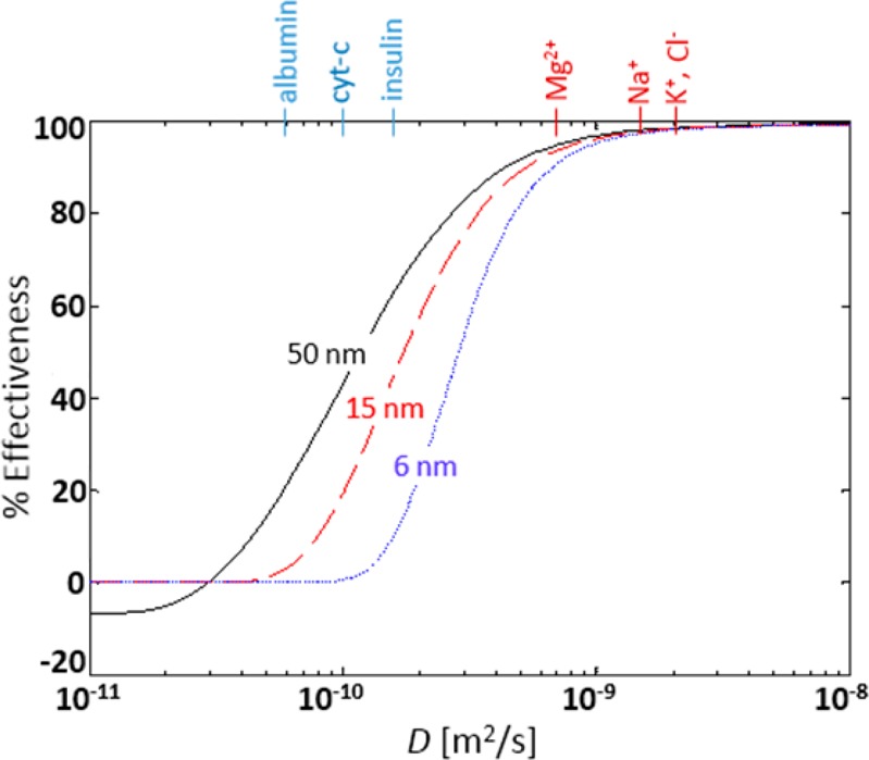
Simulation results depicting the impact of diffusion coefficient and pore size on removal effectiveness under conditions corresponding to 1.3 s residence time in Figure 2. Chemical species listed on the top axis are positioned according to their diffusion coefficients in water. Red species are interfering salt ions, while blue species are representative analytes. The negative effectiveness for very low diffusion coefficient and the largest pore size indicates an interesting effect of “analyte enrichment” by the device under these conditions. Curves are for pore diameters of 50 nm (black/solid), 15 nm (red/dashed), and 6 nm (blue/dots).
The purpose of this work is to develop, demonstrate, and make available an approach for microfabrication, with a monolithically integrated membrane, of a microfluidic device for desalting which is compatible with ambient and subambient pressure ESI-MS. The experimental results demonstrate that the device can reduce chloride ion concentration in a high concentration solution of KCl in water from 300 mM to less than 15 mM in just over a second at micro-ESI flow rates (8.3 nL/s). Furthermore, at that flow rate, we demonstrate that salt concentration reduction has the desired effect on a sample in which salt prevents analyte detection by nano-ESI-MS. It enables successful MS analysis, in spite of significant reduction in analyte concentration when the analyte diffusion coefficient differs by just over 1 order of magnitude from that of the salt. The device performance suffers currently from a “parasitic” diffusional loss of analyte; however, the experimentally validated model enables in silico investigation of the performance for different membrane pore sizes, which hinder diffusion of larger molecules in a predictable manner.31 As depicted in Figure 4, for pore sizes of 6 nm, achievable using low voltage anodization in sulfuric acid,32 analyte loss is reduced to nearly 0% while interfering salt ion removal effectiveness is retained. Further improvement would be expected through (1) reduction of buffer mass transfer resistance, (2) reduction in sample channel length for adaptation to lower nano-ESI flow rates, and (3) incorporation of a monolithically integrated nano-ESI tip.
Acknowledgments
The work described was supported by Grant Number R21GM103539 from the National Institute of General Medical Science (NIGMS), a component of the National Institutes of Health (NIH). Its contents are solely the responsibility of the authors and do not necessarily represent the official views of NIGMS or NIH. Device microfabrication and ESI-MS experiments were performed using NSF supported NNIN facilities at Georgia Tech’s Institute for Electronics and Nanotechnology (IEN).
Supporting Information Available
Additional information regarding microfabrication, experimental procedures, and model details provided as noted in text This material is available free of charge via the Internet at http://pubs.acs.org.
The authors declare no competing financial interest.
Funding Statement
National Institutes of Health, United States
Supplementary Material
References
- Fenn J. B. Angew. Chem., Int. Ed. 2003, 42, 3871–3894. [DOI] [PubMed] [Google Scholar]
- Cech N. B.; Enke C. G. Mass Spectrom. Rev. 2001, 20, 362–387. [DOI] [PubMed] [Google Scholar]
- Fenn J. B.; Mann M.; Meng C. K.; Wong S. F.; Whitehouse C. M. Science 1989, 246, 64–71. [DOI] [PubMed] [Google Scholar]
- Wilm M.; Mann M. Anal. Chem. 1996, 68, 1–8. [DOI] [PubMed] [Google Scholar]
- Bodzon-Kulakowska A.; Bierczynska-Krzysik A.; Dylag T.; Drabik A.; Suder P.; Noga M.; Jarzebinska J.; Silberring J. J. Chromatogr., B 2007, 849, 1–31. [DOI] [PubMed] [Google Scholar]
- Visser N. F.; Lingeman H.; Irth H. Anal. Bioanal. Chem. 2005, 382, 535–558. [DOI] [PubMed] [Google Scholar]
- Cavanagh J.; Benson L. M.; Thompson R.; Naylor S. Anal. Chem. 2003, 75, 3281–3286. [DOI] [PubMed] [Google Scholar]
- Sainiemi L.; Nissilä T.; Kostiainen R.; Franssila S.; Ketola R. A. Lab Chip 2012, 12, 325–332. [DOI] [PubMed] [Google Scholar]
- Liu C.; Wu Q.; Harms A. C.; Smith R. D. Anal. Chem. 1996, 68, 3295–3299. [DOI] [PubMed] [Google Scholar]
- Wu Q.; Liu C.; Smith R. D. Rapid Commun. Mass Spectrom. 1996, 10, 835–838. [Google Scholar]
- Jakubowski J. A.; Hatcher N. G.; Sweedler J. V. J. Mass Spectrom. 2005, 40, 924–931. [DOI] [PubMed] [Google Scholar]
- Sun L. L.; Duan J. C.; Tao D. Y.; Liang Z.; Zhang W. B.; Zhang L. H.; Zhang Y. K. Rapid Commun. Mass Spectrom. 2008, 22, 2391–2397. [DOI] [PubMed] [Google Scholar]
- Olivero D.; LaPlaca M.; Kottke P. A. Anal. Chem. 2012, 84, 2072–2075. [DOI] [PubMed] [Google Scholar]
- Xiang F.; Lin Y.; Wen J.; Matson D. W.; Smith R. D. Anal. Chem. 1999, 71, 1485–1490. [DOI] [PubMed] [Google Scholar]
- Xu N.; Lin Y.; Hofstadler S. A.; Matson D.; Call C. J.; Smith R. D. Anal. Chem. 1998, 70, 3553–3556. [DOI] [PubMed] [Google Scholar]
- Song S.; Singh A. K.; Shepodd T. J.; Kirby B. J. Anal. Chem. 2004, 76, 2367–2373. [DOI] [PubMed] [Google Scholar]
- Wilson D. J.; Konermann L. Anal. Chem. 2005, 77, 6887–6894. [DOI] [PubMed] [Google Scholar]
- Van Berkel G. J.; Kertesz V.; Koeplinger K. A.; Vavrek M.; Kong A.-N. T. J. Mass Spectrom. 2008, 43, 500–508. [DOI] [PubMed] [Google Scholar]
- Kottke P. A.; Degertekin F. L.; Fedorov A. G. Anal. Chem. 2010, 82, 19–22. [DOI] [PMC free article] [PubMed] [Google Scholar]
- Ramsey R. S.; Ramsey J. M. Anal. Chem. 1997, 69, 1174–1178. [DOI] [PubMed] [Google Scholar]
- Roach P. J.; Laskin J.; Laskin A. Analyst 2010, 135, 2233–2236. [DOI] [PubMed] [Google Scholar]
- Page J. S.; Tang K.; Kelly R. T.; Smith R. D. Anal. Chem. 2008, 80, 1800–1805. [DOI] [PMC free article] [PubMed] [Google Scholar]
- Jin D.-Q.; Zhu Y.; Fang Q. Anal. Chem. 2014, 86, 10796–10803. [DOI] [PubMed] [Google Scholar]
- Delendik K. I.; Voitik O. L. Proc.-SPIE Int. Soc. Opt. Eng. 2001, 4592, 355–361. [Google Scholar]
- Narayanan S.; Fedorov A.; Joshi Y. J. Micromech. Microeng. 2010, 20, 075010–075020. [Google Scholar]
- Le Gac S.; Arscott S.; Cren-Olive C.; Rolando C. J. Mass Spectrom. 2003, 38, 1259–1264. [DOI] [PubMed] [Google Scholar]
- Yoder L. J. Ind. Eng. Chem. 1919, 11, 755–755. [Google Scholar]
- Marginean I.; Kelly R. T.; Prior D. C.; LaMarche B. L.; Tang K.; Smith R. D. Anal. Chem. 2008, 80, 6573–6579. [DOI] [PMC free article] [PubMed] [Google Scholar]
- Bard A. J.; Faulkner L. R.. Electrochemical Methods: Fundamentals and Applications, 2nd ed.; Wiley: New York, 2001. [Google Scholar]
- Young M. E.; Carroad P. A.; Bell R. L. Biotechnol. Bioeng. 1980, 22, 947–955. [Google Scholar]
- Adiga S.; Curtiss L.; Elam J.; Pellin M.; Shih C.-C.; Shih C.-M.; Lin S.-J.; Su Y.-Y.; Gittard S.; Zhang J.; Narayan R. JOM 2008, 60, 26–32. [Google Scholar]
- Ono S.; Masuko N. Surf. Coat. Technol. 2003, 169–170, 139–142. [Google Scholar]
Associated Data
This section collects any data citations, data availability statements, or supplementary materials included in this article.


