Abstract
Electrophoretic mobilities and particle sizes of individual Hepatitis B Virus (HBV) capsids were measured in nanofluidic channels with two nanopores in series. The channels and pores had three-dimensional topography and were milled directly in glass substrates with a focused ion beam instrument assisted by an electron flood gun. The nanochannel between the two pores was 300 nm wide, 100 nm deep, and 2.5 μm long, and the nanopores at each end had dimensions 45 nm wide, 45 nm deep, and 400 nm long. With resistive-pulse sensing, the nanopores fully resolved pulse amplitude distributions of T = 3 HBV capsids (32 nm outer diameter) and T = 4 HBV capsids (35 nm outer diameter) and had sufficient peak capacity to discriminate intermediate species from the T = 3 and T = 4 capsid distributions in an assembly reaction. Because the T = 3 and T = 4 capsids have a wiffle-ball geometry with a hollow core, the observed change in current due to the capsid transiting the nanopore is proportional to the volume of electrolyte displaced by the volume of capsid protein, not the volume of the entire capsid. Both the signal-to-noise ratio of the pulse amplitude and resolution between the T = 3 and T = 4 distributions of the pulse amplitudes increase as the electric field strength is increased. At low field strengths, transport of the larger T = 4 capsid through the nanopores is hindered relative to the smaller T = 3 capsid due to interaction with the pores, but at sufficiently high field strengths, the T = 3 and T = 4 capsids had the same electrophoretic mobilities (7.4 × 10⁻⁵ cm2 V–1 s–1) in the nanopores and in the nanochannel with the larger cross-sectional area.
A virus capsid, the protein shell that protects the virus genome, is typically constructed of tens to hundreds of subunits, usually arranged with icosahedral or helical symmetry. Their structure and assembly are of broad interest. Capsids are used in biotechnology as containers, as platforms for vaccines, and as vehicles for novel complexes.1−3 Capsid self-assembly has been intensively studied for its value in basic science and nanotechnology.4,5 For example, Hepatitis B Virus (HBV) core (capsid) protein homodimers spontaneously assemble into two roughly spherical forms with T = 3 (90 dimers, 3 MDa, 32 nm diameter) and T = 4 (120 dimers, 4 MDa, 35 nm diameter) symmetry.6 The structure of the HBV capsid is known, its in vitro assembly is well characterized, and its in vivo assembly has been identified as an antiviral target.7−11 A means of examining and identifying individual complete and defective capsids in solution has many applications.
Resistive-pulse sensing with nanopores detects MDa-sized biomolecules with single-particle resolution12 and can be used to understand population heterogeneity. Moreover, single-particle measurements complement ensemble methods, which often obscure contributions from individual species. We are developing electrophoretic methods that track individual virus particles in solution, in real time, and without the use of fluorescent labels. These methods also return physical parameters, e.g., particle size and electrophoretic mobility. To conduct single-particle electrophoresis13−15 of single virus capsids,16 we have fabricated a nanochannel with two nanopores in series into a microfluidic device that detects individual HBV capsids. Detection at the nanopores is accomplished by resistive-pulse sensing, in which changes in conductivity are detected when particles transit an electrically biased nanopore.17 Each conductivity change (or pulse) has an amplitude and width proportional to size and mobility of the particle, respectively. Resistive-pulse sensing is well suited to study single virus-sized nanoparticles in solution because of its high signal-to-noise ratio.18−20
Conventional resistive-pulse sensing with a single nanopore typically detects each particle a single time. Size discrimination is achieved in both pulse amplitude and width.21−23 The residence time within the nanopore (or pulse width) is used to calculate electrophoretic mobility when particle size < pore length.24,25 However, additional information can be obtained when multiple measurements are made on a single particle. Passing a single particle back and forth through a single pore in a controlled manner provides information on particle dynamics26,27 and diffusion.28,29 Averaging together multiple measurements made on a single particle provides greater precision in particle sizing.30 When multiple pores are connected in series, a single particle is detected multiple times, and the migration time between pores is used to calculate electrophoretic mobility. Two solid-state pores stacked vertically in a device measure the time-of-flight of DNA between the pores.15 With an in-plane approach, however, virtually any two-dimensional architecture can be designed and tested. Two nanopores arranged in plane and in series sense HBV capsids.16 An alternative geometry to sensing particles at channel constrictions is to connect several openings (or nodes) in series, where the node pattern is imprinted on each pulse to extend the dynamic range for the measurement.31
Devices for resistive-pulse sensing can be fabricated by a number of methods. Focused ion beam (FIB) milling permits fabrication of nanopores32 and nanochannels33 whose dimensions can be easily tailored through appropriate control of the ion beam dose. With ion beam milled nanopores, DNA strands are detected, and the levels of current displacement are assigned to various degrees of strand folding.34 FIB-milled nanochannels are used to measure the effect of nanochannel dimensions on DNA mobility by fluorescence microscopy35 and to sense DNA translocation by resistive-pulse sensing.36 Moreover, lateral conductance measurements of DNA molecules transiting through a nanoscale cross intersection offer an alternative method to axial conductance measurements.37 In conventional FIB milling, glass substrates are typically coated with a conductive film, e.g., metal, to effectively compensate for charge buildup of ions on the substrate surface and to minimize beam drift during milling. In this work, we milled nanoscale channels directly into an uncoated glass substrate with an FIB instrument. During fabrication of the nanochannels, we used an electron flood gun to minimize charging on the substrate surface, circumvent the need to incorporate a conductive film, and simplify the fabrication process.
We characterized device performance with fully formed HBV capsids with outer diameters of 32 nm (T = 3) and 35 nm (T = 4). The 3 nm difference in the outer diameters of the T = 3 and T = 4 capsids is easily resolved, and the relative current displacements from the translocation events are proportional to the volume of capsid protein. Also, the relative pulse counts of the T = 4 to T = 3 capsids mirror the expected capsid ratios in solution, which indicates that the transport of the capsids through the nanopores is not biased toward the smaller T = 3 capsids. Both the pulse amplitudes and signal-to-noise ratios for the capsids increase with increasing field strength. The pulse widths are used to calculate the electrophoretic mobilities of the capsids in the nanopores, and the pore-to-pore times are used to calculate the electrophoretic mobilities of the capsids between the two pores. At low field strengths, transport of the larger T = 4 capsids through the nanopores is hindered slightly due to interaction with the nanopores, and consequently, the T = 4 capsids have a lower mobility than the smaller T = 3 capsids. However, at high field strengths, the electrophoretic mobilities estimated from the pulse widths of the capsids in the nanopores match the electrophoretic mobilities measured from the pore-to-pore times. Finally, we demonstrate that the FIB-milled nanopore devices provide sufficient peak capacity to analyze the products from virus assembly reactions and are able to resolve intermediate species from the T = 3 and T = 4 capsid distributions during a 120 min reaction.
Experimental Section
Materials
We purchased sodium chloride from Mallinckrodt, Inc.; 4-(2-hydroxyethyl)-1-piperazineethanesulfonic acid (HEPES) and methanol from Sigma-Aldrich Co.; ammonium hydroxide from J.T. Baker; hydrogen peroxide from Macron Fine Chemicals; sodium hydroxide from Fisher Scientific; Microposit MF-319 developer from Rohm and Haas Electronic Materials; chromium etchants 8002-A and 1020 and buffered oxide etchant from Transene Co., Inc.; D263 mask blanks from Telic Co.; #1.5 coverslip glass from VWR, Inc.; Anotop 10 syringe filters from Whatman GmbH; and 353NDT Epoxy from Epoxy Technology, Inc.
Virus Capsids
HBV capsids were assembled from core protein (Cp149, 17 kDa) dimers expressed in E. coli and purified as described previously.38 After assembly, the T = 3 and T = 4 capsids were separated from free dimer and each other in a 10%–40% (w/v) continuous sucrose gradient in 50 mM HEPES (pH 7.5) with 300 mM NaCl that was centrifuged for 6 h at 150 000g. The upper particle band (T = 3 capsids) and the lower particle band (T = 4 capsids) were extracted, dialyzed into 50 mM HEPES (pH 7.5) with 1 M NaCl, and concentrated to a final concentration of 0.2–0.3 mg/mL. Sample purity and the ratio of T = 4 to T = 3 capsids were verified by transmission electron microscopy (JEM-1010, JEOL Ltd.); samples were adsorbed to glow-discharged carbon-coated grids (EM Sciences) and stained with 2% uranyl acetate.
Device Fabrication
The microchannels were fabricated by standard UV photolithography and wet chemical etching, as described previously.39 D263 glass substrates coated with 120 nm of Cr and 530 nm of AZ1518 photoresist were exposed to 200 mJ/cm2 UV radiation through a photomask (HTA Photomask). The photoresist was developed for 2 min in the MF-319 developer, and the microchannel pattern was transferred to the chromium layer by etching for 8 min in chromium etchant 8002-A. Finally, microchannels were etched in buffered oxide etchant to a depth of 9.33 ± 0.03 μm and width of 40 μm. Dimensions of the microchannels were determined with a stylus-based profiler (Dektak 6M, Veeco Instruments, Inc.). Access holes were sandblasted at the ends of the microchannels (AEC Air Eraser, Paasche Airbrush Co.) before removal of the remaining photoresist with acetone and chromium with chromium etchant 1020. Substrates were cleaned with a solution of NH4OH, H2O2, and H2O (2:1:2) at 70 °C for 20 min, sonicated in water, and dried overnight in a 90 °C furnace.
The nanochannel and nanopores were milled directly into the glass substrates with a focused ion beam (FIB) instrument (Auriga 60, Carl Zeiss, GmbH) controlled by the NanoPatterning and Visualization Engine (NPVE; FIBICS, Inc.). The nanochannel was milled in three steps. The nanochannel sections that connected the pores with the microchannels were milled with a 30 kV beam at 50 pA and a dose of 1 nC/μm2. The pore-to-pore channel was milled with the same accelerating potential and beam current, but with a dose of 0.5 nC/μm2. The two nanopores were milled as a single line pass with a 30 kV beam at 20 pA and a dose of 0.006 μC/μm to connect the three nanochannel sections. During the FIB milling on the glass substrate, an electron flood gun (FG 15/40, SPECS, GmbH) operated at 5 eV and 20 μA compensated for the buildup of positive charge on the substrate surface. Device dimensions were determined with the SEM on the FIB instrument and an AFM (MFP-3D, Asylum Research, Inc.). To bond the devices, the substrates and #1.5 cover glass were hydrolyzed in a solution of 1 M NaOH for 15 min at 70 °C, sonicated in water, brought into contact with each other, dried overnight at 90 °C, and annealed in a furnace at 545 °C for 10 h. Glass reservoirs were epoxied over sandblasted holes.
Resistive-Pulse Measurements
Channels were sequentially filled with methanol, methanol/water (1:1), water, 100 mM NaOH, water, and 50 mM HEPES buffer (pH 7.5) with 1 M NaCl. All solutions were filtered with 20 nm syringe filters. For the sensing and electrophoresis measurements, 1 nM solutions of T = 3 HBV capsids (3.06 MDa, 32 nm outer diameter), T = 4 HBV capsids (4.08 MDa, 35 nm outer diameter), or mixtures of T = 3 and T = 4 capsids in 50 mM HEPES buffer with 1 M NaCl were placed in the capsid reservoir. For the assembly experiment, 8.5 μM Cp149 dimer in 50 mM HEPES buffer (pH 7.5) was mixed with 50 mM HEPES buffer (pH 7.5) and 50 mM HEPES buffer (pH 7.5) with 2 M NaCl to achieve a final concentration of 0.9 μM Cp149 in 50 mM HEPES with 1 M NaCl to initiate assembly. The reaction mixture was loaded into the capsid reservoir, and a vacuum was applied to draw the reaction mixture into the microchannel and adjacent to the nanochannel. The assembly reaction was monitored from 1.5 min after initial mixing up to 120 min.
Electrical measurements were conducted inside a stainless steel Faraday cage (1 ft × 1 ft × 1 ft) covered in 2″ acoustic wedge foam. Ag/AgCl electrodes were placed inside the buffer-filled reservoirs, and an Axopatch 200B current amplifier (Molecular Devices, Inc.) was used to apply the potential between the capsid and waste reservoirs (Figure 1a) and to measure the current. Collection frequencies of 20 and 40 kHz and filter frequencies of 5 and 10 kHz were used for the sensing and assembly experiments, respectively.
Figure 1.
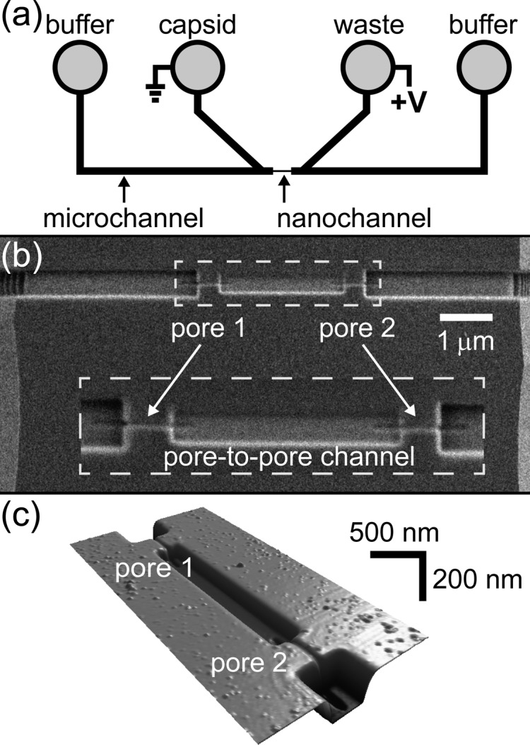
(a) Schematic of the microfluidic device with two V-shaped microchannels separated by a 10-μm gap. The nanochannel with two pores was milled with a focused ion beam instrument to bridge the two microchannels as shown by the scanning electron microscope (SEM) image in panel b and the atomic force microscope (AFM) image in panel c. The pores are 45 nm wide, 45 nm deep, and 430 nm long; the pore-to-pore channel is 300 nm wide, 104 nm deep, and 2.5-μm long; and the channels that connect the pores to the microchannels are 510 nm wide and 210 nm deep. In panel b, the dashed box is an enlarged view of the two pores and pore-to-pore channel, which is the 2.5-μm-long channel between pores 1 and 2.
We used three devices for the sensing and electrophoresis experiments and one device for the assembly experiment. The resistances in the nanochannel and nanopores were calculated by treating the micro- and nanochannels as a series of resistors, for which the resistance in each segment is proportional to the channel length over the cross-sectional area. For the devices in the sensing experiments, 96% of the potential was dropped across the nanochannel with ∼35% of the applied potential dropped across each pore. Nanopores were etched slightly by NaOH during the bonding process, and final pore dimensions were calculated by conductivity measurements. Current data were imported into OriginPro 9.0 (OriginLab Corp.) to subtract the baseline current and to determine the pulse amplitude (Δi), pulse width (w), and pore-to-pore transit time (tpp) for each capsid that transited the two pores in series.
Results and Discussion
Resistive-Pulse Sensing
Resistive-pulse sensing was conducted with the device design shown in Figure 1. Two V-shaped microchannels are bridged by a 10-μm-long nanochannel composed of channel sections with three sets of dimensions (Figure 1b,c). The dimensions of the two nanopores are tailored to sense HBV capsids; the pores are 45 ± 5 nm wide, 45 ± 5 nm deep, and 430 ± 20 nm long. The two nanochannel sections that connect the pores to the microchannels are milled to a width of 510 ± 10 nm and a depth of 210 ± 1 nm. The pore-to-pore channel formed between pores 1 and 2 is 300 ± 4 nm wide, 104 ± 1 nm deep, and 2.5 μm long and has one-third the cross-sectional area of the nanochannel sections that connect the pores to the microchannels.
The nanochannel design has two key improvements over our earlier device design for two-pore sensing.16 First, focused ion beam (FIB) milling enables fabrication of nanochannels in three dimensions where the nanochannel dimensions are tuned by varying the ion beam dose. Consequently, the pores are small enough to sense individual virus capsids, and the nanochannels adjacent to the pores have larger cross sections to reduce overall device resistance. With the design in Figure 1, ∼35% of the applied potential is dropped across each pore, and 70% of the applied potential is dropped across both pores. Having the resistance of each nanopore account for a larger fraction of the total resistance enhances the pulse amplitude relative to the baseline current and improves the signal-to-noise ratio. Second, the pore-to-pore channel with the reduced cross-sectional area has a higher field strength relative to the nanochannels that connect the pores to the microchannels. Due to the higher field strength, a 20% decrease in the relative standard deviation of the pore-to-pore velocity distribution was observed in these devices compared to identical two-pore devices without a reduced cross-sectional area in the pore-to-pore channel (data not shown).
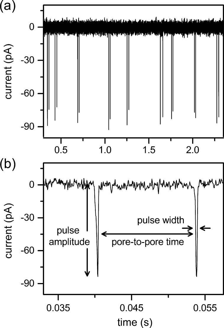
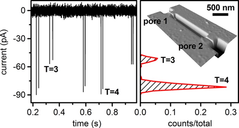
The HBV capsids are electrokinetically driven along the nanochannel and through the two nanopores. The presence of the capsid in the pore increases the resistance in the pore and, consequently, reduces the ion current. The pulse generated in the current trace has a pulse amplitude (Δi) proportional to the volume of the capsid protein and a pulse width (w) proportional to the residence time of the capsid in the pore. A series of nine two-pulse events is shown in Figure 2a, and a single two-pulse event is shown in Figure 2b. The pore-to-pore time (tpp) is the time between pulses from the trailing edge of the first pulse to the leading edge of the next pulse and is used to calculate capsid velocity in the nanochannel and, subsequently, electrophoretic mobility. Due to slight differences in the pore dimensions, the pulse amplitude for each capsid is reported as the average amplitude from pores 1 and 2. Applied potentials up to 600 mV were tested with stable operation at baseline currents up to 18 nA.
Figure 2.
(a) Variation of current with time for nine two-pulse events of Hepatitis B Virus (HBV) capsids passing through a two-pore nanochannel with an applied potential of 600 mV. (b) Two-pulse event for a single T = 4 HBV capsid with pulse amplitude, pulse width, and pore-to-pore time labeled.
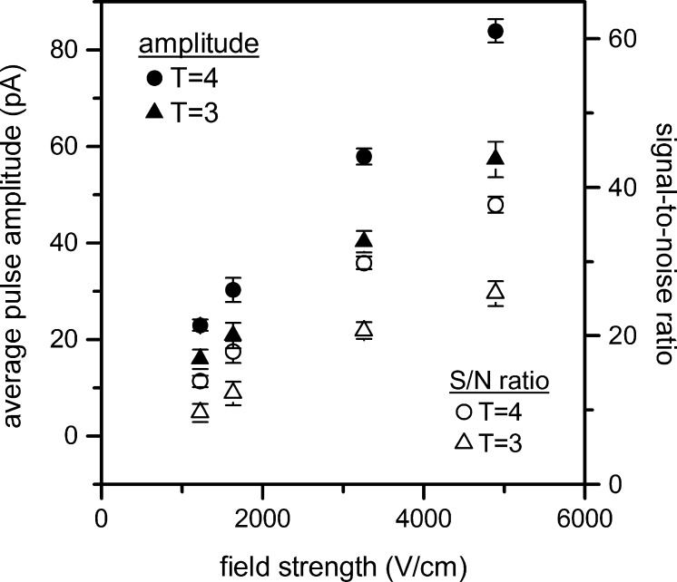
Discrimination between particle sizes is apparent in the differences in their pulse amplitude. Figure 3 shows that the pulse amplitudes for the T = 3 and T = 4 capsids increase as applied potential and electric field strength in the pores increase. Interestingly, the root-mean-square baseline noise increases at a much lower slope than the pulse amplitudes, and consequently, the signal-to-noise ratios (S/N ratio) for the T = 3 and T = 4 capsids increase with the electric field strength in the pore. At all applied potentials, the larger T = 4 capsids (35 nm outer diameter) displace an average of 0.56% of the baseline current, and the smaller T = 3 capsids (32 nm outer diameter) displace an average of 0.39% of the baseline current. Previous reports indicate that the pulse amplitude for a spherical particle passing through a sufficiently long pore (pore length ≫ particle diameter) is proportional to particle volume.18,40,41
Figure 3.
Variation of average pulse amplitude and signal-to-noise ratio (S/N ratio) for T = 3 and T = 4 capsids with electric field strength in the nanopore. Error bars are ±σ for 150 capsids for each measurement.
However, the ratio of the particle volume (assuming a solid sphere) to pore volume for T = 4 capsids is estimated to have a relative current displacement of 2.5%, over 4 times the measured displaced current. The discrepancy between the calculated and measured relative current displacement can be explained by capsid geometry, which is better approximated as a porous spherical shell, or “wiffle ball,” filled with electrolyte. Current displacement by the capsid should be proportional to envelope (or protein) volume, and not solid volume.42 From image reconstructions of cryo-electron microscopy data, the thickness of the capsid shell is estimated to be 2.5 nm, and porosity of the capsid shell is estimated to be 35%.43 Relative current displacement is calculated by dividing the wiffle ball volume by the sensing nanopore volume:
| 1 |
where rout is the outer radius of the capsid (17.5 nm for the T = 4 capsid and 16 nm for the T = 3 capsid), s is the capsid shell thickness (2.5 nm), Φ is capsid porosity (0.35), lp is nanopore length (430 nm), wp is nanopore width (45 nm), and dp is nanopore depth (45 nm). The relative current displacements calculated for the wiffle-ball model are 0.61% for T = 4 capsids and 0.50% for T = 3 capsids, which correspond well to the measured values, 0.56% and 0.39%, respectively. Because the capsid geometry is not uniform as estimated by eq 1, an alternative method to estimate the relative current displacement is to calculate the ratio of protein volume for each capsid to pore volume. With 0.742 cm3/g as the protein density,43 the T = 4 capsid (4.08 MDa) has a protein volume to pore volume ratio of 0.58%, and the T = 3 capsid (3.06 MDa) has a protein volume to pore volume ratio of 0.43%. These values are in excellent agreement with the measured current displacement.
Size Discrimination
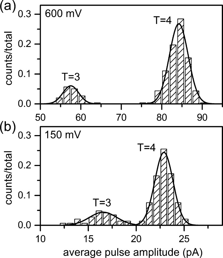
Resistive-pulse measurements are sensitive to small differences in analyte diameter, and the 3 nm difference between the outer diameters of the T = 3 and T = 4 capsids is easily resolved. Figure 4 shows histograms of the pulse amplitudes of the T = 3 and T = 4 capsids at low and high field strength. At low field strength (150 mV applied), the larger T = 4 capsids displaced an average current of 22.9 ± 0.95 pA, whereas the smaller T = 3 capsids displaced an average current of 16.5 ± 1.4 pA. As field strength increases, pulse amplitude and resolution between the pulse amplitude distributions increase. At high field strength (600 mV applied), the T = 4 capsids displaced an average current of 84.2 ± 2.3 pA, and the T = 3 capsids displaced an average current of 57.5 ± 1.9 pA. Resolution between the pulse-amplitude distributions increases from 2.7 at low field strength to 6.2 at high field strength, a factor of 2.3. (Resolution is defined as the difference between the means of the distributions divided by the average width of the distributions (4σ).) Of particular interest is the ability to resolve pulse-amplitude distributions of intermediate capsid sizes that may fall below the T = 3 distribution or between the T = 3 and T = 4 distributions.
Figure 4.
Histograms of average pulse amplitude for T = 3 and T = 4 HBV capsids at (a) high field strength (600 mV applied potential) and (b) low field strength (150 mV applied potential). Lines are Gaussian fits to the pulse amplitude distributions for 150 capsids in panel a and 300 capsids in panel b.
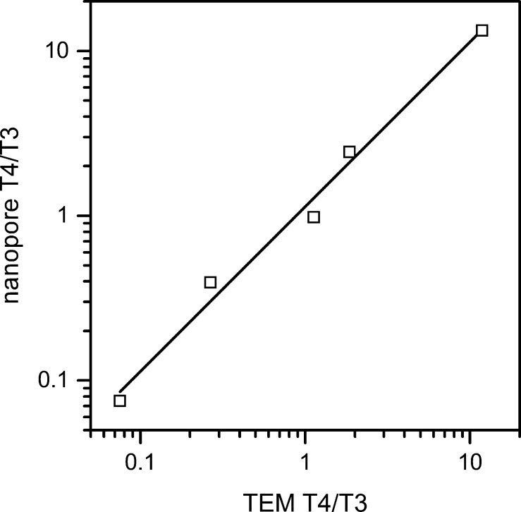
Relative pulse counts from five ratios of T = 4 to T = 3 capsids determined if the measured capsid ratios matched the expected ratios. In Figure 5, the ratios of T = 4 to T = 3 pulse counts from the resistive-pulse measurements are plotted against the ratios of capsid sizes obtained from negative-stained electron micrographs. At an applied potential of 140 mV, pulse amplitudes less than 18.5 pA are counted as T = 3 capsids, and pulse amplitudes greater than 18.5 pA are counted as T = 4 capsids (compare to Figure 4b). The capsid ratios from the resistive-pulse measurements correlate extremely well with the capsid ratios from the TEM images. The linear fit to the data has a slope of 1, which indicates the nanopores do not preferentially sense the smaller T = 3 capsids. In other words, the larger T = 4 capsids do not experience a larger entropic barrier to enter the nanopores than the smaller T = 3 capsids, which can complicate interpretation of data collected with smaller nanopores.20
Figure 5.
Ratios of T = 4 to T = 3 counts from resistive-pulse measurements with the nanopores (nanopore T4/T3) and from negative-stain electron microscopy (TEM T4/T3). The linear fit has a slope of 1, indicating the count ratio is not biased toward the smaller T = 3 capsid. Counts are 484 capsids for the nanopore ratios and 2000 capsids for the TEM ratios.
Electrokinetic Mobilities
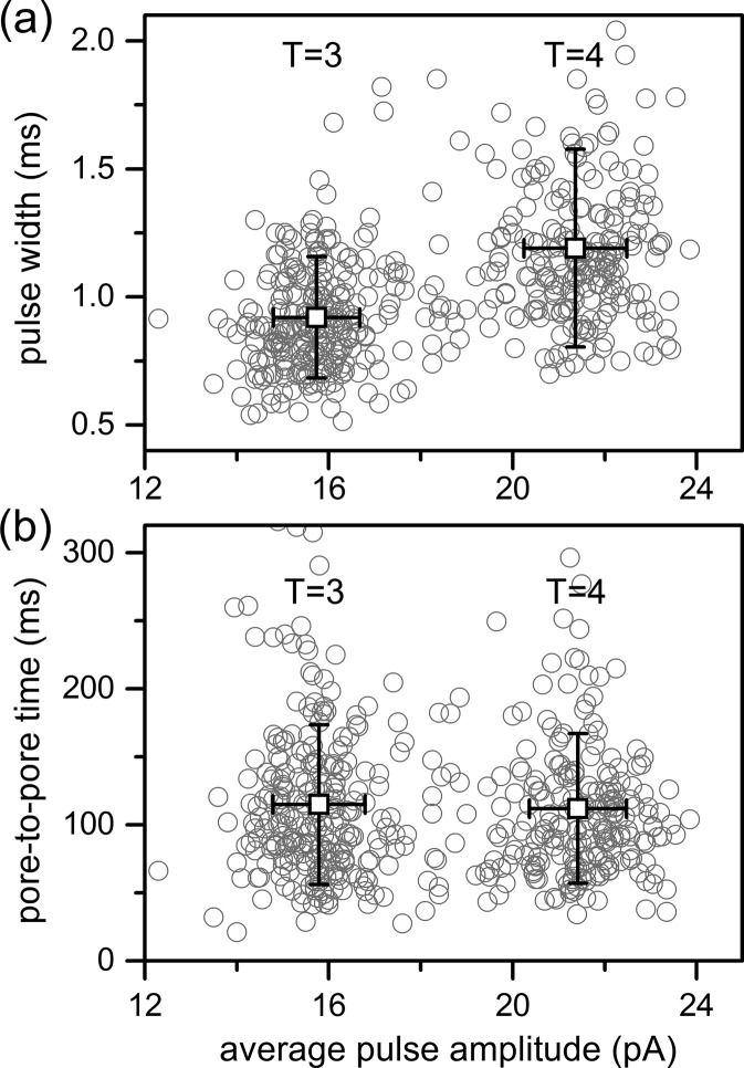
At low field strengths, the larger T = 4 capsids produced pulse widths that were 1.2 ± 0.4 ms, whereas the smaller T = 3 capsids produced pulse widths that were 0.92 ± 0.24 ms (Figure 6a). These pulse widths are statistically different (t(481) = 9.45; p < 0.001). Pulse width is the residence time of the capsid within the pore, and this difference in pulse widths indicates that the larger T = 4 capsids are interacting with (e.g., adsorbing to) the pore wall more frequently than the smaller T = 3 capsids when there is an insufficient force (e.g., applied potential) driving the T = 4 capsids through the pore. The increased diameter and surface area of the T = 4 capsid compared with the T = 3 capsid may be responsible for more frequent adsorption events to the glass surface.44 Although pulse width shows a size dependence, the times between pulses (pore-to-pore times) for T = 3 and T = 4 capsids are essentially identical (Figure 6b). The average pore-to-pore times are 112 ± 55 ms for the T = 4 capsids and 115 ± 57 ms for T = 3 capsids and are statistically indistinguishable (t(481) = 0.59; p = 0.56).
Figure 6.
Variation of pulse width and pore-to-pore time with average pulse amplitude for T = 3 and T = 4 capsids at an applied potential of 140 mV. Pulse widths for the T = 4 capsids (1.2 ± 0.4 ms) are wider than the pulse widths for the T = 3 capsids (0.92 ± 0.24 ms), whereas pore-to-pore times for the T = 4 capsids (112 ± 55 ms) are the same as the pore-to-pore times for the T = 3 capsids (115 ± 57 ms). Open squares are the averages for each distribution, and error bars are ±σ for 484 capsids.
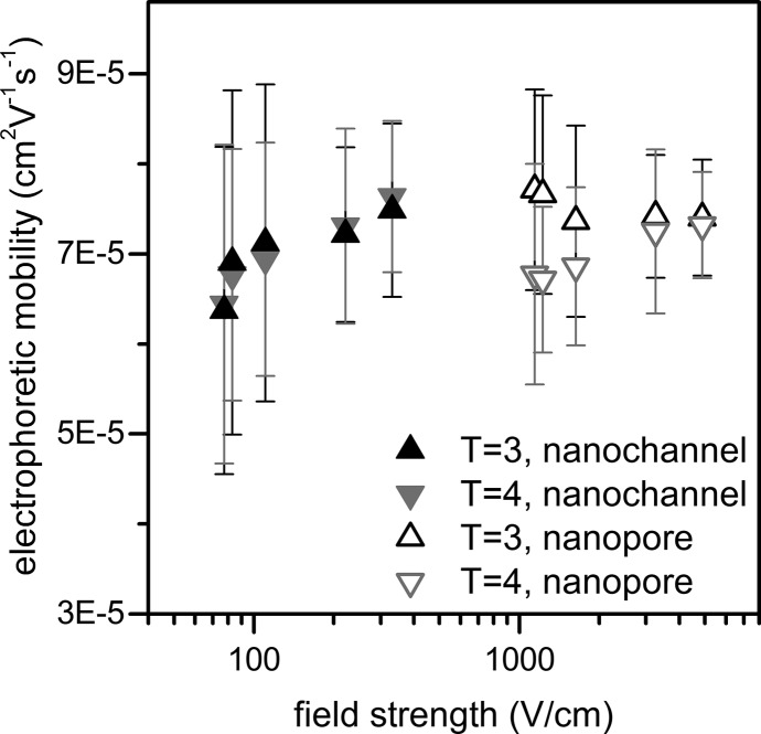
Electrophoretic mobilities in the pores and pore-to-pore channel were calculated from the pulse widths and pore-to-pore times, respectively, and are plotted as a function of field strength (Figure 7). Electrokinetic mobility (μek) is the sum of the electrophoretic (μep) and electroosmotic (μeo) mobilities.
| 2 |
At 1 M NaCl, the electroosmotic mobility is greatly reduced due to the small electrical double layer thickness45 and was experimentally determined to be 3.5 ± 0.1 × 10⁻⁵ cm2 V–1 s–1 in a glass nanochannel that was 54 nm deep, 530 nm wide, and 76 μm long.46 Because electrophoretic transport of the capsids is in the opposite direction of the electroosmotic transport, the electroosmotic mobility is added to the measured electrokinetic mobility to determine the electrophoretic mobilities for the T = 3 and T = 4 capsids plotted in Figure 7.
Figure 7.
Variation of electrophoretic mobility with electric field strength for T = 3 and T = 4 capsids in the nanopores and pore-to-pore nanochannel. At the lower field strengths in the nanopores, the T = 4 capsids have a lower electrophoretic mobility than the T = 3 capsids due to interaction with the pore. At higher field strengths, the nanopore and nanochannel electrophoretic mobilities converge to 7.4 × 10⁻⁵ cm2 V–1 s–1. Error bars are ±σ for 1330 capsids.
Electrophoretic mobility can exhibit a slight field strength dependence47 and is observed to increase in both the pores and pore-to-pore channel with field strength. The electrophoretic mobilities calculated from pore-to-pore times are identical for T = 3 and T = 4 capsids for all fields tested and approach a constant value above 80 V/cm. However, the electrophoretic mobilities calculated from the pulse width depend on capsid size. Smaller T = 3 capsids exhibit a higher electrophoretic mobility in the nanopore than the larger T = 4 capsids at low field strength, but the difference disappears as the field strength increases. The nanopore electrophoretic mobility of individual T = 4 capsids at low field strengths exhibits a log-normal distribution and shifts toward a normal distribution as field strength increases. This trend suggests that some capsids are interacting with the pore, e.g., adsorbing to the pore wall, at low field strengths, and these interactions lower the average electrophoretic mobility of the T = 4 capsids in the pores. This effect is also evident in pulse width (Figure 6a).
Electrophoretic mobilities in the pores and pore-to-pore channel converge to the same value at high field strengths, and the average electrophoretic mobilities are calculated for each capsid at the highest field strengths tested. The electrophoretic mobilities in the pore-to-pore channel are 7.5 ± 0.9 × 10⁻⁵ cm2V–1 s–1 for the T = 4 capsids and 7.4 ± 0.9 × 10⁻⁵ cm2 V–1 s–1 for the T = 3 capsids. The electrophoretic mobilities in the nanopores are 7.3 ± 0.8 × 10⁻⁵ cm2 V–1 s–1 for the T = 4 capsids and 7.4 ± 0.7 × 10⁻⁵ cm2 V–1 s–1 for the T = 3 capsids. These measured electrophoretic mobilities are in agreement with mobilities calculated from similarly sized virus particles.48
Virus Assembly
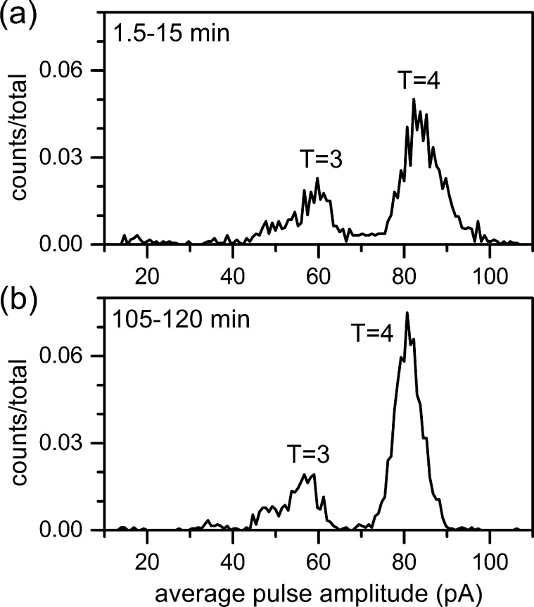
We monitored the assembly of HBV dimer into T = 3 and T = 4 capsids with a nanofluidic device. Dimensions for the device used in the assembly experiment differed slightly from the device used in the sensing and electrophoresis experiments. The nanopores had a larger cross-section (60 ± 5 nm wide and 60 ± 5 nm deep) and shorter lengths (206 ± 6 nm), and the pore-to-pore nanochannel had the same cross-section (300 ± 4 nm wide and 104 ± 1 nm deep) but a shorter length (1.00 ± 0.02 μm). Pores with larger cross-sectional areas passed aggregates formed during the reaction more readily, and the shorter pore-to-pore channel easily resolved the pore-to-pore times between adjacent events at higher dimer concentrations. To initiate assembly, Cp149 dimer was mixed with buffer to a final concentration of 0.9 μM dimer in 50 mM HEPES (pH 7.5) with 1 M NaCl, and the reaction was monitored from 1.5 to 120 min (Figure 8). With an applied potential of 425 mV, the T = 4 distribution is centered at 81 pA, and the smaller T = 3 distribution is centered at 57 pA. In the first 15 min of assembly (Figure 8a), a range of late-stage intermediates are detected adjacent to the T = 3 and T = 4 distributions. For example, a trapped intermediate that displaces an average current of 48 pA and corresponds to a 79-dimer species persists during the assembly reaction. A continuum of intermediates is present between the T = 3 and T = 4 distributions, as observed in experiments with charge detection mass spectrometry.49 As the reaction proceeds, the number of T = 4 capsids increases, the T = 4 distribution narrows, and the intermediate population decreases significantly (Figure 8b). The T = 3 distribution remains constant over the course of the measurement. These nanopore devices generate sufficient peak capacity to capture species as small as 24 dimers yet track a number of intermediate distributions during the assembly reaction.
Figure 8.
Histograms of average pulse amplitude for assembly of 0.9 μM Cp149 dimer for (a) 1.5–15 min of assembly and (b) 105–120 min of assembly. (a) With 425 mV applied potential, T = 3 and T = 4 capsids have distributions centered at 59 pA and 82 pA of current, respectively, and intermediate species are observed adjacent to these distributions. (b) As the assembly experiment proceeds, the number of T = 4 capsids increases, the T = 4 distribution narrows, and the number of intermediate species decreases. Counts are 1926 particles in panel a and 2119 particles in panel b.
Conclusion
We have demonstrated single-particle electrophoresis in a nanochannel with a nanopore at each end. The 3 nm difference in the outer diameters of the T = 3 and T = 4 capsids is easily resolved by their relative current displacement, which is proportional to the volume of capsid protein, not the volume of the whole capsid. Also, the relative pulse counts of the T = 4 to T = 3 capsids mirror the expected capsid ratios, which suggests that the larger T = 4 capsid is not entropically hindered to enter the pore. We will use these devices to further our studies of HBV assembly. To date, the short-lived intermediate structures formed in the assembly reaction have only been studied through mathematical models.4,50 Our single particle measurements in real time will be used to determine what intermediate species exist under different assembly conditions.
Acknowledgments
This work was supported in part by NIH R01 GM100071, NSF CHE-0923064, and NSF CHE-1308484 for Z.D.H, D.G.H., A.R.K., and S.C.J. and by NIH R01 GM100071 for L.S. and A.Z. The authors thank the Indiana University Nanoscale Characterization Facility for use of its instruments.
The authors declare no competing financial interest.
Funding Statement
National Institutes of Health, United States
References
- Douglas T.; Young M. Science 2006, 312, 873–875. [DOI] [PubMed] [Google Scholar]
- Dragnea B. Nat. Mater. 2008, 7, 102–104. [DOI] [PubMed] [Google Scholar]
- Yildiz I.; Shukla S.; Steinmetz N. F. Curr. Opin. Biotechnol. 2011, 22, 901–908. [DOI] [PMC free article] [PubMed] [Google Scholar]
- Zlotnick A.; Mukhopadhyay S. Trends Microbiol. 2011, 19, 14–23. [DOI] [PMC free article] [PubMed] [Google Scholar]
- Hagan M. F. In Adv. Chem. Phys.; John Wiley & Sons, Inc.: New York, 2014; Vol. 155, pp 1–68. [DOI] [PMC free article] [PubMed] [Google Scholar]
- Crowther R. A.; Kiselev N. A.; Bottcher B.; Berriman J. A.; Borisova G. P.; Ose V.; Pumpens P. Cell 1994, 77, 943–950. [DOI] [PubMed] [Google Scholar]
- Wynne S. A.; Crowther R. A.; Leslie A. G. W. Mol. Cell 1999, 3, 771–780. [DOI] [PubMed] [Google Scholar]
- Katen S.; Zlotnick A. Methods Enzymol. 2009, 455, 395–417. [DOI] [PMC free article] [PubMed] [Google Scholar]
- Katen S. P.; Tan Z. N.; Chirapu S. R.; Finn M. G.; Zlotnick A. Structure 2013, 21, 1406–1416. [DOI] [PMC free article] [PubMed] [Google Scholar]
- Li L. C.; Chirapu S. R.; Finn M. G.; Zlotnick A. Antimicrob. Agents Chemother. 2013, 57, 1505–1508. [DOI] [PMC free article] [PubMed] [Google Scholar]
- Wu G. Y.; Liu B.; Zhang Y. J.; Li J.; Arzumanyan A.; Clayton M. M.; Schinazi R. F.; Wang Z. H.; Goldmann S.; Ren Q. Y.; Zhang F. X.; Feitelson M. A. Antimicrob. Agents Chemother. 2013, 57, 5344–5354. [DOI] [PMC free article] [PubMed] [Google Scholar]
- Piruska A.; Gong M.; Sweedler J. V.; Bohn P. W. Chem. Soc. Rev. 2010, 39, 1060–1072. [DOI] [PubMed] [Google Scholar]
- Wang H.; Dunning J. E.; Huang A. P. H.; Nyamwanda J. A.; Branton D. Proc. Natl. Acad. Sci. U. S. A. 2004, 101, 13472–13477. [DOI] [PMC free article] [PubMed] [Google Scholar]
- Castro A.; Shera E. B. Anal. Chem. 1995, 67, 3181–3186. [Google Scholar]
- Langecker M.; Pedone D.; Simmel F. C.; Rant U. Nano Lett. 2011, 11, 5002–5007. [DOI] [PubMed] [Google Scholar]
- Harms Z. D.; Mogensen K. B.; Nunes P. S.; Zhou K.; Hildenbrand B. W.; Mitra I.; Tan Z.; Zlotnick A.; Kutter J. P.; Jacobson S. C. Anal. Chem. 2011, 83, 9573–9578. [DOI] [PMC free article] [PubMed] [Google Scholar]
- Zhou K.; Perry J. M.; Jacobson S. C. In Ann. Rev. Anal. Chem.; Annual Reviews: Palo Alto, CA, 2011; Vol. 4, pp 321–341. [DOI] [PubMed] [Google Scholar]
- DeBlois R. W.; Bean C. P. Rev. Sci. Instrum. 1970, 41, 909–916. [Google Scholar]
- Uram J. D.; Ke K.; Hunt A. J.; Mayer M. Small 2006, 2, 967–972. [DOI] [PubMed] [Google Scholar]
- Zhou K.; Li L.; Tan Z.; Zlotnick A.; Jacobson S. C. J. Am. Chem. Soc. 2011, 133, 1618–1621. [DOI] [PMC free article] [PubMed] [Google Scholar]
- Harrell C. C.; Choi Y.; Horne L. P.; Baker L. A.; Siwy Z. S.; Martin C. R. Langmuir 2006, 22, 10837–10843. [DOI] [PubMed] [Google Scholar]
- Lan W. J.; Holden D. A.; Zhang B.; White H. S. Anal. Chem. 2011, 83, 3840–3847. [DOI] [PubMed] [Google Scholar]
- Li W.; Bell N. A. W.; Hernandez-Ainsa S.; Thacker V. V.; Thackray A. M.; Bujdoso R.; Keyser U. F. ACS Nano 2013, 7, 4129–4134. [DOI] [PubMed] [Google Scholar]
- Ito T.; Sun L.; Bevan M. A.; Crooks R. M. Langmuir 2004, 20, 6940–6945. [DOI] [PubMed] [Google Scholar]
- Kozak D.; Anderson W.; Vogel R.; Chen S.; Antaw F.; Trau M. ACS Nano 2012, 6, 6990–6997. [DOI] [PubMed] [Google Scholar]
- Berge L. I.; Feder J.; Jossang T. Rev. Sci. Instrum. 1989, 60, 2756–2763. [Google Scholar]
- German S. R.; Luo L.; White H. S.; Mega T. L. J. Phys. Chem. C 2013, 117, 703–711. [Google Scholar]
- Gershow M.; Golovchenko J. A. Nat. Nanotechnol. 2007, 2, 775–779. [DOI] [PMC free article] [PubMed] [Google Scholar]
- Schiel M.; Siwy Z. S. J. Phys. Chem. C 2014, 118, 19214–19223. [Google Scholar]
- Sen Y. H.; Jain T.; Aguilar C. A.; Karnik R. Lab Chip 2012, 12, 1094–1101. [DOI] [PMC free article] [PubMed] [Google Scholar]
- Balakrishnan K. R.; Anwar G.; Chapman M. R.; Nguyen T.; Kesavaraju A.; Sohn L. L. Lab Chip 2013, 13, 1302–1307. [DOI] [PubMed] [Google Scholar]
- Li J.; Stein D.; McMullan C.; Branton D.; Aziz M. J.; Golovchenko J. A. Nature 2001, 412, 166–169. [DOI] [PubMed] [Google Scholar]
- Stokes D. J.; Vystavel T.; Morrissey F. J. Phys. D, Appl. Phys. 2007, 40, 874–877. [Google Scholar]
- Li J.; Gershow M.; Stein D.; Brandin E.; Golovchenko J. A. Nat. Mater. 2003, 2, 611–615. [DOI] [PubMed] [Google Scholar]
- Campbell L. C.; Wilkinson M. J.; Manz A.; Camilleri P.; Humphreys C. J. Lab Chip 2004, 4, 225–229. [DOI] [PubMed] [Google Scholar]
- Fanzio P.; Mussi V.; Manneschi C.; Angeli E.; Firpo G.; Repetto L.; Valbusa U. Lab Chip 2011, 11, 2961–2966. [DOI] [PubMed] [Google Scholar]
- Menard L. D.; Mair C. E.; Woodson M. E.; Alarie J. P.; Ramsey J. M. ACS Nano 2012, 6, 9087–9094. [DOI] [PMC free article] [PubMed] [Google Scholar]
- Zlotnick A.; Ceres P.; Singh S.; Johnson J. M. J. Virol. 2002, 76, 4848–4854. [DOI] [PMC free article] [PubMed] [Google Scholar]
- Zhuang Z.; Starkey J. A.; Mechref Y.; Novotny M. V.; Jacobson S. C. Anal. Chem. 2007, 79, 7170–7175. [DOI] [PubMed] [Google Scholar]
- Ito T.; Sun L.; Henriquez R. R.; Crooks R. M. Acc. Chem. Res. 2004, 37, 937–945. [DOI] [PubMed] [Google Scholar]
- Davenport M.; Healy K.; Pevarnik M.; Teslich N.; Cabrini S.; Morrison A. P.; Siwy Z. S.; Létant S. E. ACS Nano 2012, 6, 8366–8380. [DOI] [PubMed] [Google Scholar]
- Horak D.; Peska J.; Svec F.; Stamberg J. Powder Technol. 1982, 31, 263–267. [Google Scholar]
- Zlotnick A.; Cheng N.; Conway J. F.; Booy F. P.; Steven A. C.; Stahl S. J.; Wingfield P. T. Biochemistry 1996, 35, 7412–7421. [DOI] [PubMed] [Google Scholar]
- Sexton L. T.; Mukaibo H.; Katira P.; Hess H.; Sherrill S. A.; Horne L. P.; Martin C. R. J. Am. Chem. Soc. 2010, 132, 6755–6763. [DOI] [PubMed] [Google Scholar]
- Rice C. L.; Whitehead R. J. Phys. Chem. 1965, 69, 417–424.14274328 [Google Scholar]
- Haywood D. G.; Harms Z. D.; Jacobson S. C. Anal. Chem. 2014, 86, 11174–11180. [DOI] [PMC free article] [PubMed] [Google Scholar]
- Salieb-Beugelaar G. B.; Teapal J.; van Nieuwkasteele J.; Wijnperle D.; Tegenfeldt J. O.; Lisdat F.; van den Berg A.; Eijkel J. C. T. Nano Lett. 2008, 8, 1785–1790. [DOI] [PubMed] [Google Scholar]
- Kremser L.; Bilek G.; Blaas D.; Kenndler E. J. Sep. Sci. 2007, 30, 1704–1713. [DOI] [PubMed] [Google Scholar]
- Pierson E. E.; Keifer D. Z.; Selzer L.; Lee L. S.; Contino N. C.; Wang J. C. Y.; Zlotnick A.; Jarrold M. F. J. Am. Chem. Soc. 2014, 136, 3536–3541. [DOI] [PMC free article] [PubMed] [Google Scholar]
- Hagan M. F.; Elrad O. M. Biophys. J. 2010, 98, 1065–1074. [DOI] [PMC free article] [PubMed] [Google Scholar]


