Abstract
Retinal vein cannulation (RVC) is a challenging procedure proposed for drug delivery into the very small retinal veins. The available glass cannulas for this procedure are both hard to visualize and fragile thereby limiting the feasibility of both robot-assisted and manual RVC approaches. In this study, we develop and test a new force-sensing RVC instrument that can be easily integrated with the existing manual and robotic devices. The tool enables (1) the measurement of the forces required for puncturing retinal veins in vivo and (2) an assistive method to inform the operator of the needle piercing the vessel wall. The fiber Bragg grating based sensor can be inserted into the eye through a small (∅ 0.9 mm) opening and provides a quantitative assessment at the tool tip with a resolution smaller than 0.25 mN. Assessment of forces during vessel penetration in the chorioallantoic membranes of chicken embryos have revealed a consistent sharp drop in tool tip force upon vessel puncture that has been used as a signature to provide auditory feedback to the user to stop needle advancement and begin drug delivery.
Keywords: force sensing, fiber Bragg grating, vein cannulation
I. Introduction
Retinal vein cannulation (RVC) proposes to treat retinal vein occlusion by direct therapeutic agent delivery methods. During the procedure, clot-dissolving plasminogen activator (t-PA) is injected into the occluded vein [1]. The fine, sharp tips of drawn glass micropipettes enable injection into very small veins. However, their transparency and fragility result in visibility and safety issues. As a more rigid and visible alternative, stainless steel microneedles were proposed [2]. Tests on porcine eyes showed that microneedles are more feasible instruments for microvascular surgery than the glass micropipettes, which was further supported by successful clinical demonstrations on human retinal veins [3]. Despite these improvements, visualizing the tool tip using the operating biomicroscope is still not trivial, and the operation still requires accurate manipulation of extremely delicate tissues inside of the eye, which puts RVC at the limits of human performance.
There are three main challenges associated with RVC: (1) guiding the tool tip onto the target retinal vein accurately, (2) piercing the vein wall and stopping the cannula insertion at the correct depth, and (3) maintaining the needle tip inside of the vessel during drug injection. Retinal veins are very small structures (∅ 60–100 μm) and injection into these veins requires the use of even smaller microneedles. On the other hand, the physiological hand tremor of vitreoretinal surgeons has been measured at over 100 μm in amplitude [4], which significantly hinders accurate aiming during needle insertion as well as the ability to maintain cannulation during injection. As a remedy, teleoperated [5], cooperatively controlled [6], and handheld [7] robotic devices were proposed for RVC. Although smooth and accurate tool motion is achieved via these robotic systems, challenges to identifying the vessel puncture, establishing cannulation and maintaining it during drug injection persists.
In other applications involving needle insertion into blood vessels, such as sampling blood from the forearm, much larger forces compared to retinal microsurgery are applied, which enables the clinician to sense puncture and identify the moment at which the needle enters the blood vessel [8]. On the other hand, the required forces for cannulating human retinal veins are almost imperceptible. Tests on chorioallantoic membrane (CAM) of chicken embryos, have been reported to be a valid in vivo model for human RVC studies [9], and have confirmed that most RVC forces are below the human perception threshold [10], yet with similar force variation trends observed in forearm blood sampling [11]. Thus, feedback based on the applied forces can potentially indicate the moment of vessel puncture in RVC as well, thereby allowing the operator to appropriately begin drug injection without causing further damage to the vasculature. Utilization of such force signatures though requires the ability to measure micro-forces inside of the eye.
To provide force feedback in retinal microsurgery, a family of force-sensing instruments was developed at JHU using fiber Bragg grating (FBG) strain sensors. These tools were developed in two forms, hook [12,13] or micro-forceps [14–16], to assist specifically membrane peeling in vitreoretinal practice. The force sensing architecture in these designs enables accurate measurement of micro-forces directly at the tool tip with sub-mN resolution. This paper reports a new force-sensing RVC instrument following a similar architecture that can easily be integrated with the existing manual tools, and robotic devices. The tool enables (1) the measurement of the forces required for puncturing retinal veins in vivo and (2) an assistive method to inform the operator of the needle piercing the vessel wall. In the following sections we will first present the design of our tool. This will be followed by cannulation experiments using CAM of fertilized chicken eggs. The paper concludes with a discussion of the results.
II. Force-Sensing Microneedle
A. Mechanical Design
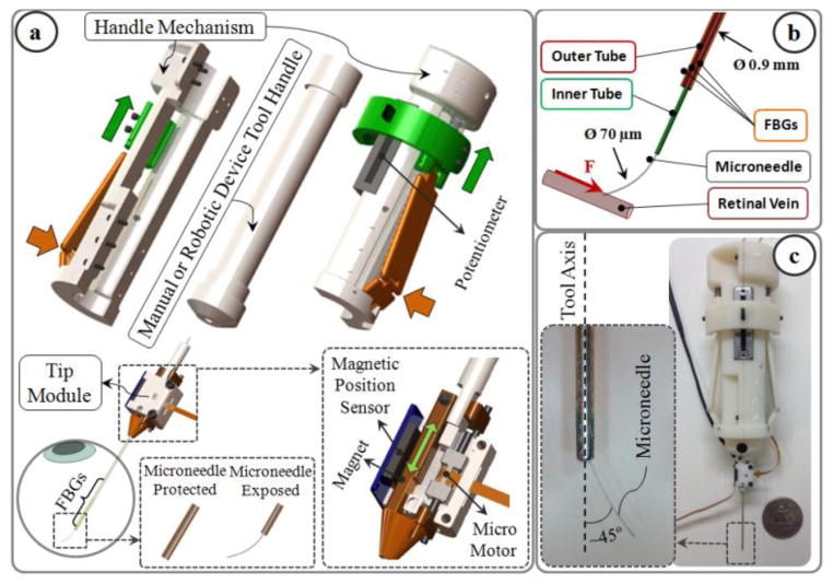
The design consists of two units: tip module, and the handle mechanism (Fig. 1a). The tip module carries a linear micro motor, Squiggle-RV-1.8 by New Scale Technologies Inc., driving a slider back and forth along the pins of the base. The tool shaft is formed by two concentric steel tubes (Fig. 1b). The outer 23 Ga tube is attached to the slider and performs two main functions: (1) it carries the force sensing FBGs which will be detailed in section II.B; (2) it functions as a mobile protective cover for the microneedle. The inner 30 Ga tube is fixed relative to the base, carries the injection fluid, and is connected to the microneedle at the tool apex. The microneedle has a beveled tip and is pre-bent, 45° relative to the tool axis, to enable more gradual and thus safer approach to the retina surface. The needle tip has an outer diameter of 70 μm for injection into very small retinal veins (~∅ 100 μm). It is kept protected and straight inside the outer tube before insertion into the eye. Upon reaching the target vessel site, the outer tube, attached to the slider mechanism, is retracted back via the linear micro motor, and the sharp microneedle tip is exposed for cannulation (Fig. 1a). Fully covering and exposing the microneedle requires a travel of 5 mm. The selected micro motor supplies enough force and travel for this task in a very small (2.8×2.8×6 mm), and light weight (0.16 grams) package. There is a bar magnet located on the side of the slider. The position of the slider, and thus of the micro motor, is tracked via the position sensor fixed on the side of the base to enable closed loop position control of the motor. This ensures accurate motion of the outer tube despite the potentially variable friction at the insertion port through the sclera. The outer diameter of the tip module tool shaft is small enough to fit through a ∅ 0.9 mm incision on the sclera.
Fig. 1.
(a) Force-sensing microneedle tool concept: the tip module and the handle mechanism. (b) The inner tube of the tool shaft delivers the injection fluid, while 3 FBG sensors on the outer tube sense transverse forces on the microneedle tip. (c) Manufactured prototype. Microneedle tip is pre-bent, 45° relative to the tool axis, to enable more gradual approach to the retina surface.
The handle mechanism is a simple interface for controlling the motor actuation. It can clamp around any cylindrical manual or robotic tool handle up to 25 mm in diameter. The spring loaded sides of the mechanism are normally kept propped open. Squeezing the sides pushes the sliders up, and changes the voltage output of the connected potentiometer to drive the micro motor back, thus retracts the outer tube and exposes the microneedle tip (Fig. 1a).
B. Integrated Force Sensing
Detection of vessel puncture while cannulating vessels on CAM, and similarly retinal veins, requires the integration of a very sensitive force sensor with sub-mN resolution on the described tip module. Since the forces at the sclera insertion port can be much larger than the typical cannulation forces at the tool tip, the force sensing elements need to be located close to the tool apex and inside of the eye. FBG strain sensors (Smart Fibers, UK), with their small dimension, high sensitivity, biocompatibility, sterilizability, and immunity from electrostatic and electromagnetic noise satisfy these criteria.
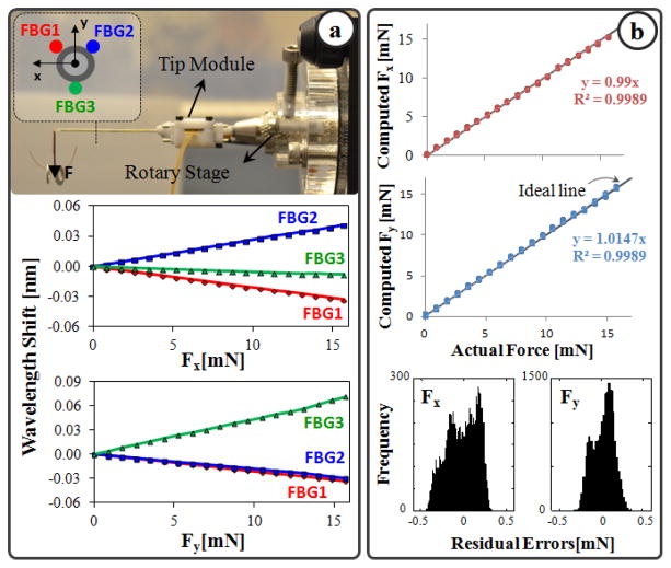
Sensing only the transverse loads on the tool tip is sufficient for RVC since due to design (bent tip), forces induced on the tool tip during insertion will be mostly lateral. To integrate this capability onto the tip module, 3 FBGs were fixed evenly around the 23 Ga outer tube (Fig. 1b) using medical epoxy adhesive following the fabrication method presented in [12]. The calibration setup and protocol of the force sensor also follow [12]. All FBGs exhibit a linear reproducible behavior during both the x- and y-axis calibration procedures, as shown in Fig. 2a. The slopes of the response curves form the calibration matrix (K). The pseudo-inverse of this matrix (K+) is used in the linear relationship (1) to compute the transverse tool tip forces (Fx and Fy) from FBG wavelength shifts (ΔS) during the operation.
Fig. 2.
(a) Calibration results: linear response for all FBGs when the tip is loaded along x and y axes. (b) Computed forces versus the actual forces along x and y axes. (c) The histogram of the residual errors.
| (1) |
In order to monitor the FBGs, an optical sensing interrogator, sm130–700 from Micron Optics Inc. (Atlanta GA), was used. The wavelength resolution of the interrogator is 1 pm. Based upon the obtained calibration matrix, this corresponds to a transverse force resolution of about 0.22 mN, which is sufficient to detect the very fine changes in RVC. For verification, computed forces were compared with actual forces while the tip was loaded and unloaded repeatedly in different angles. Results showed consistency with the actual force values for both Fx and Fy, and a close fit to the ideal straight line (slope=1) through the origin (Fig. 2b). The root mean square (RMS) error is 0.18 mN and 0.21 mN respectively for Fx and Fy. The histogram of the residual errors in Fig. 2b show that the probability of errors beyond 0.5 mN for Fx and Fy is very low.
III. System Integration and Control Scheme
The tip module in this design packs its own actuator and sensors in a single compact independently actuated unit. In addition, the tip module and the handle mechanism are mechanically decoupled from each other. This enables easy integration with the existing manual tools and robotic devices such as in [5–7]. The control scheme of the force-sensing microneedle does not interfere with the operation of the integrated tool, and consists of two independent loops: micro motor control loop, and force feedback loop (Fig. 3).
Fig. 3.
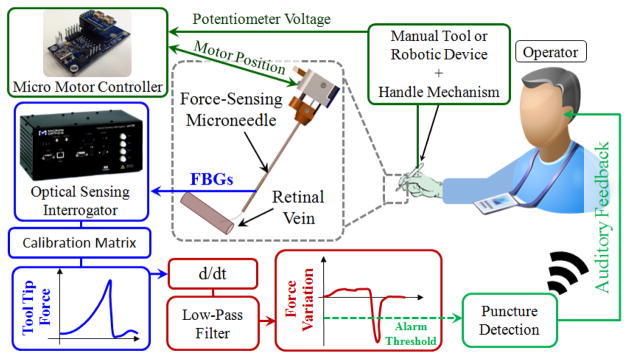
(a) Control scheme. The potentiometer of the handle mechanism drives the motor of the tip module, thus exposes the microneedle tip. The time derivative of sensed forces is low-pass filtered to identify the instant of vessel puncture, and generate an alarm sound to the operator.
Analog position servo input to the motor controller is provided by the sliding potentiometer on the handle mechanism. The magnetic sensor on the tip module feeds the motor position back to the controller to accomplish accurate closed loop control, exposing or protecting the microneedle tip without noticeable delay. In earlier needle puncture studies using rabbit ear veins [8] and CAM of fertilized chicken eggs [10], a characteristic force behavior was reported. After the needle tip touched the tissue surface, the insertion force gradually rose until a sharp drop signaling the entrance of needle tip into the vein. The force feedback control loop in our control scheme aims to identify this instant and alert the operator so that the needle does not overshoot and stays inside of the vessel. For this aim, a custom LabVIEW program was developed. During the operation, first, the wavelength information from each FBG channel is collected and processed at 1 kHz and transmitted over TCP/IP to the LabVIEW environment. Using the calibration matrix, the transverse force at the tool tip is obtained. Then, the time derivative of tip force is computed and passed through a second-order low-pass filter. The optimal filter parameters (cutoff frequency and damping coefficient) were tuned based on measured force profiles in [10] so that the sharp drop, thus the vessel puncture, could be detected with minimal delay. If the filtered derivative of force is less than a certain threshold (0.005 mN/s for CAM), then the operator is warned with an alarm sound so that the needle advancement is stopped.
IV. Experiments
To assess the feasibility of force-sensing microneedle, vein cannulation experiments were performed on the setup shown in Fig. 4 by a non-surgeon subject with no prior cannulation experience. To simulate the retina and its vasculature, CAM of 12-day-old chicken embryos were used due to their similar anatomical features and histological properties [9]. The tip module with the force-sensing microneedle was mounted on the handle of an optically tracked micromanipulator, Micron [7]. The Micron manipulator in the current tests was used as a passive tool handle only for the purpose of accurate tool tip tracking due its embedded infrared light-emitting diodes (LEDs) and the position-sensitive-detector cameras, namely the ASAP tracker. The Micron handle was fixed on a linear stage for driving the needle tip at constant speed along a straight trajectory. The microneedle was kept exposed at all times so that the use of the handle mechanism was not needed.
Fig. 4.
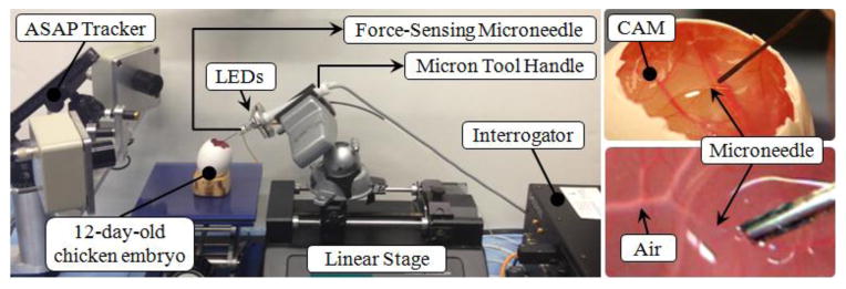
Setup for vein cannulation experiments on CAM of 12-day fertilized chicken eggs. The force-sensing microneedle was driven by a linear stage at constant speed while its position was recorded by the ASAP tracker.
Before starting the experiment, the eggshell was partially removed to access the inner shell membrane (ISM). Then, the ISM was carefully peeled off using fine forceps to remove any variability in tests due to ISM thickness, and directly expose CAM. Tests were done driving the microneedle at two different levels of speed in alternating sequence: 0.3 mm/s and 0.5 mm/s. 8 trials were completed for each speed level. The task in each test was to cannulate a small vessel and inject air into it. The target vessels on CAM were chosen to be within 100–140 μm in diameter using a fine fiber (∅ 125 μm) for reference. After identifying the target, the microneedle was aimed and driven toward the vessel using the linear stage. The tip forces were monitored and an alarm sound was provided by the system upon sensing a puncture event. After hearing the alarm sound, the linear stage was stopped by the operator, and air injection was started. The success of vessel puncture, thus the implemented force feedback mechanism, was assessed based on the observation of air bubbles flowing in the vessel. For statistical analyses t-test assuming unequal variances was used with p<0.05 for statistical significance.
V. Results and Discussion
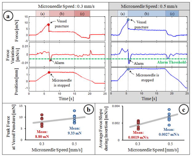
Typical results for each speed level are shown in Fig. 5a. After the microneedle touched the CAM surface, a gradually rising force, thus a positive force gradient was observed. At the end of phase (a), the microneedle pierced the vessel wall, which caused a sharp drop in the force and a sudden negative gradient triggering the auditory feedback mechanism. After the alarm sound, the stage was stopped manually and the needle was held in place during phase (b) while the operator started air injection to verify successful cannulation. During this time, the tool tip force remained the same. Then, the needle was retracted back while smaller forces in the opposite direction were measured at the tool tip.
Fig. 5.
(a) A representative cannulation trial from each speed setting. The sharp drop in force signifies vessel puncture and generates an alarm to warn the operator. (b,c) Force statistics for 8 trials per speed setting.
In all trials, successful cannulation was achieved regardless of the speed setting. Although the overall force trend remained the same, statistical analyses revealed the effect of linear stage speed on the observed force variation and peak force values. As shown in Fig. 5b, the mean rate of change in force during phase (a) was higher in 0.5 mm/s setting (0.0027 mN/s) than the 0.3 mm/s setting (0.0019 mN/s) (p=0.0043). The mean peak force also increased with higher insertion speed (Fig. 5c), yet this was not a statistically significant difference (p=0.588). In both Fig. 5b and 5c, the variation among the tests within each speed setting is mainly due to minor differences between embryos and selected vessel diameters.
VI. Conclusion
In this study, we developed a force-sensing microneedle tool enabling an assistive feedback mechanism for cannulating retinal veins more easily. The designed hardware is presumably compatible and can easily be integrated onto many of the existing assistive robotic devices without interfering with their own control system. The force-sensing tip module is able to detect transverse forces on the tool tip with a resolution below 0.25 mN. The implemented feedback mechanism informs the operator upon vessel puncture and prevents overshoot based on the time derivative of sensed tool tip forces. Experiments on fertilized chicken eggs have shown 100% success in cannulating ∅ 100–140 μm vessels, validating the use of such feedback based on force signatures in cannulation. In these experiments, the microneedle was driven by a linear stage at constant speed providing ease in testing such a time derivative based function. For practical use, similar tool stability and cannulation success with the same feedback mechanism can potentially be achieved by integrating the developed force-sensing microneedle with one of the existing tremor-canceling robotic devices. Our current work focuses on integration and evaluation of this technology.
Acknowledgments
This work was supported in part by the National Institutes of Health under R01 EB007969, and R01 EB000526, and in part by Johns Hopkins University internal funds.
Contributor Information
Berk Gonenc, Email: bgonenc1@jhu.edu, CISST ERC at Johns Hopkins University, Baltimore, MD 21218 USA.
Peter Gehlbach, Email: pgelbach@jhmi.edu, Wilmer Eye Institute at The Johns Hopkins School of Medicine, Baltimore, MD 21287 USA.
James Handa, Email: jthanda@jhmi.edu, Wilmer Eye Institute at The Johns Hopkins School of Medicine, Baltimore, MD 21287 USA.
Russell H. Taylor, Email: rht@jhu.edu, CISST ERC at Johns Hopkins University, Baltimore, MD 21218 USA.
Iulian Iordachita, Email: iordachita@jhu.edu, CISST ERC at Johns Hopkins University, Baltimore, MD 21218 USA.
References
- 1.Weiss JN, Bynoe LA. Injection of tissue plasminogen activator into a branch retinal vein in eyes with central vein occlusion. Ophthalmology. 2001 Jul;108(12):2249–2257. doi: 10.1016/s0161-6420(01)00875-2. [DOI] [PubMed] [Google Scholar]
- 2.Kadonosono K, Arakawa A, Yamane S, Uchio E, Yanagi Y. An experimental study of retinal endovascular surgery with a fabricated needle. Invest Opthalmol Vis Sci. 2011 Jul;52(8):5790–5793. doi: 10.1167/iovs.11-7327. [DOI] [PubMed] [Google Scholar]
- 3.Kadonosono K, Yamane S, Arakawa A, Inoue M, Yamakawa T, Uchio E, Yanagi Y, Amano S. Endovascular cannulation with a microneedle for central retinal vein occlusion. JAMA Ophthalmol. 2013 Jun;131(6):783–786. doi: 10.1001/jamaophthalmol.2013.2585. [DOI] [PubMed] [Google Scholar]
- 4.Singh SPN, Riviere CN. Physiological tremor amplitude during retinal microsurgery. Proc IEEE 28th Annu. Northeast Bioeng. Conf; 2002; pp. 171–172. [Google Scholar]
- 5.Ueta T, Yamaguchi Y, Shirakawa Y, Nakano T, Ideta R, Noda Y, Morita A, Mochizuki R, Sugita N, Mitsuishi M. Robot-assisted vitreoretinal surgery: Development of a prototype and feasibility studies in an animal model. Ophthalmology. 2009 Aug;116(8):1538–1543. doi: 10.1016/j.ophtha.2009.03.001. [DOI] [PubMed] [Google Scholar]
- 6.Fleming I, Balicki M, Koo J, Iordachita I, Mitchell B, Handa J, Hager G, Taylor R. Cooperative robot assistant for retinal microsurgery. Med Image Comput Comput Assist Interv. 2008;5242:543–550. doi: 10.1007/978-3-540-85990-1_65. [DOI] [PubMed] [Google Scholar]
- 7.Becker BC, Yang S, MacLachlan RA, Riviere CN. Towards vision-based control of a handheld micromanipulator for retinal cannulation in an eyeball phantom. Proc. 4th IEEE RAS EMBS Int. Conf. Biomed. Robot. Biomechatron. (BioRob); 2012; pp. 44–49. [DOI] [PMC free article] [PubMed] [Google Scholar]
- 8.Saito H, Togawa T. Detection of needle puncture to blood vessel using puncture force measurement. Med Biol Eng Comput. 2005 Mar;43(2):240–244. doi: 10.1007/BF02345961. [DOI] [PubMed] [Google Scholar]
- 9.Leng T, Miller JM, Bilbao KV, Palanker DV, Huie P, Blumenkranz MS. The chick chorioallantoic membrane as a model tissue for surgical retinal research and simulation. Retina. 2004 Jun;24(3):427–434. doi: 10.1097/00006982-200406000-00014. [DOI] [PubMed] [Google Scholar]
- 10.Ergeneman O, Pokki J, Pocepcova V, Hall H, Abbott JJ, Nelson BJ. Characterization of puncture forces for retinal vein cannulation. J Med Dev. 2011 Dec;5(4):044504. [Google Scholar]
- 11.Zivanovic A, Davies BL. A robotic system for blood sampling. IEEE Trans Inf Technol Biomed. 2000 Mar;4(1):8–14. doi: 10.1109/4233.826854. [DOI] [PubMed] [Google Scholar]
- 12.Iordachita I, Sun Z, Balicki M, Kang J, Phee S, Handa J, Gehlbach P, Taylor R. A sub-millimetric, 0.25 mn resolution fully integrated fiber-optic force-sensing tool for retinal microsurgery. International Journal of Computer Assisted Radiology and Surgery. 2009 Jun;4:383–390. doi: 10.1007/s11548-009-0301-6. [DOI] [PMC free article] [PubMed] [Google Scholar]
- 13.He X, Handa J, Gehlbach P, Taylor R, Iordachita I. A sub-milimetric 3-dof force sensing instrument with integrated fiber Bragg grating for retinal microsurgery. IEEE Trans Biomed Eng. 2014 Feb;61(2):522–534. doi: 10.1109/TBME.2013.2283501. [DOI] [PMC free article] [PubMed] [Google Scholar]
- 14.He X, Balicki MA, Kang JU, Gehlbach PL, Handa JT, Taylor RH, Iordachita II. Force sensing micro-forceps with integrated fiber bragg grating for vitreoretinal surgery. Proc of SPIE. 2012 Feb;8218:82180W 1–7. [Google Scholar]
- 15.Kuru I, Gonenc B, Balicki M, Handa J, Gehlbach P, Taylor RH, Iordachita I. Force Sensing Micro-Forceps for Robot Assisted Retinal Surgery. Proc. International Conference of the IEEE EMBS (EMBC ’12); 2012; pp. 1401–1404. [DOI] [PMC free article] [PubMed] [Google Scholar]
- 16.Gonenc B, Feldman E, Gehlbach P, Handa J, Taylor RH, Iordachita I. Towards Robot-Assisted Vitreoretinal Surgery: Force-Sensing Micro-Forceps Integrated with a Handheld Micromanipulator. Proc. IEEE Int. Conf. on Robotics and Automation (ICRA ’14); 2014; pp. 1399–1404. [DOI] [PMC free article] [PubMed] [Google Scholar]
- 17.Gonenc B, Handa J, Gehlbach P, Taylor RH, Iordachita I. A Comparative Study for Robot Assisted Vitreoretinal Surgery: Micron vs. the Steady-Hand Robot. Proc. IEEE Int. Conf. on Robotics and Automation (ICRA ’13); 2013; pp. 4832–4837. [DOI] [PMC free article] [PubMed] [Google Scholar]


