

Abstract
In this paper we describe an FPGA-based platform for high-performance and low-power simulation of neural microcircuits composed from integrate-and-fire (IAF) neurons. Based on high-level synthesis, our platform uses design templates to map hierarchies of neuron model to logic fabrics. This approach bypasses high design complexity and enables easy optimization and design space exploration. We demonstrate the benefits of our platform by simulating a variety of neural microcircuits that perform oscillatory path integration, which evidence suggests may be a critical building block of the navigation system inside a rodent’s brain. Experiments show that our FPGA simulation engine for oscillatory neural microcircuits can achieve up to 39× speedup compared to software benchmarks on commodity CPU, and 232× energy reduction compared to embedded ARM core.
I. Introduction
Large-scale neural microcircuits are essential for a better understanding of the mystery behind the brain, and are increasingly being used to solve information processing tasks in an expanding range of engineering and robotic applications. Efforts on high performance computer clusters and customized hardware have been undertaken to accelerate such simulations (Section V). However, many applications require a combination of high performance, low power and reconfigurability.
To achieve optimal energy-efficiency, many previous approaches explored the ASIC design for neural microcircuit constructions. However, with the fast advance of neuroscience, neural models are evolving constantly, and the lack of flexibility and high cost impede its popularity in the neuron simulation domain. As a result, FPGA has been favored as hardware accelerator for neuron simulation in recent work [1]–[4], and was demonstrated to achieve better performance and energy-efficiency compared to CPUs and GPUs. However, although impressive optimizations have been presented by prior work, it is uncertain if many of the particular optimizations are adaptable for a wider range of more complex and larger-scale neural microcircuits. Moreover, FPGA design often require complex knowledge of RTL coding and FPGA architecture, which makes it difficult for experts in neuron simulation to produce an efficient design.
With the recent advance of high-level synthesis technologies [5], it is possible to archive significantly better programmability and adaptability, with small trade-offs in performance and resource usage. In this paper, we present a platform-based methodology that uses Xilinx Vivado highlevel synthesis tools [6] for constructing FPGA simulations of neural microcircuits.
In neuron simulations, each neuron cell is modeled as one or more compartments; neuron cells sharing the same properties form a population; and populations of neurons form circuits. Neuron compartments are modeled as electrical circuits that represent membrane voltage, current and conductance. A neural microcircuit is populations of neurons connected together through spiking events that increase or decrease membrane voltage through synaptic conductance. Exploiting such hierarchical structure, our platform defines a neural microcircuit with XML-based descritions, and generates C code for high-level synthesis tools using design templates. In our platform, neuron populations are mapped to computing engines, in which the neuron cells are simulated with integration pipelines.
Therefore, compared to previous FPGA implementations of neuron simulation, our platform-based methodology has the following advantages:
Our approach enables rapid construction of FPGA simulation engines throughout the domain of neuron simulation. Taking advantages of the hierarchical structure shared by most spiking neuron models, our platform can generate efficient hardware implementations with design templates and high-level synthesis tools.
Based on high-level description of neural microcircuits, our platform enables the domain experts in neural modeling to synthesize high-performance and energy-efficient neuron simulation engines without extensive knowledge of the FPGA design details. When creating or modifying a neuron simulation, the model configurations made by domain experts can be automatically mapped to the corresponding FPGA implementation.
With our platform, the task of exploring design tradeoffs and performance optimization is also simplified. Optimizations can be performed at each level of the simulation without violating the semantics of the model.
The simulation methods described in this paper are broadly adaptable for constructing FPGA-based simulations for other IAF model architectures. We demonstrate the benefits of our approach by implementing a selection of neural microcircuits for oscillatory path integration, which is believed to aid a rodents navigation by constructing spatial maps of an environment using a process similar to Fourier synthesis [7]–[10]. Combining our methodology with a high-level description of neural microcircuits, FPGA implementation can offer much better performance and energy-efficiency than software-based implementations, without sacrificing much on flexibility and productivity.
This paper is organized as follows. In Section II we briefly introduce the hierarchies of neural microcircuits using the example of oscillatory neural microcircuit. We then present our platform-based methodology of constructing neural microcircuit simulation engines in Section III. We demonstrate the performance of our platform using a selection of neural microcircuit simulations in Section IV. Finally, we provide discussions of related work in Section V, and we conclude our paper in Section VI.
II. Neural Microcircuit Model
In this section we discuss the general modeling method used in neural microcircuits simulation with the example of circuits that conduct oscillatory path integration. Most animals (including humans) can keep track of their own location as they navigate through a familiar environment, even in darkness or when blindfolded. This ability depends upon path integration, the process of computing position by integrating movement velocity over time [11]–[14]. It has been hypothesized that these neurons derive their spatial tuning properties from neural oscillators with frequencies that are modulated by the speed and direction of an animal’s movements through space [7]–[9], [15].
We introduce the model by breaking the microcircuit into a hierarchical structure: compartments, cells, populations and circuits. The higher-level objects are composed from the lower-level components. An example architecture of the oscillatory microcircuit is illustrated in Fig. 1, which implements a spiking network for path integration by neural oscillators, as proposed by prior theoretical models [7]–[10]. The circuit module is made up of two different circuits called VCO rings and grid sheets. Each circuit is composed from populations of single-compartment IAF neurons. In the remaining part of this section, we discuss each level of the neuron model in details.
Fig. 1.
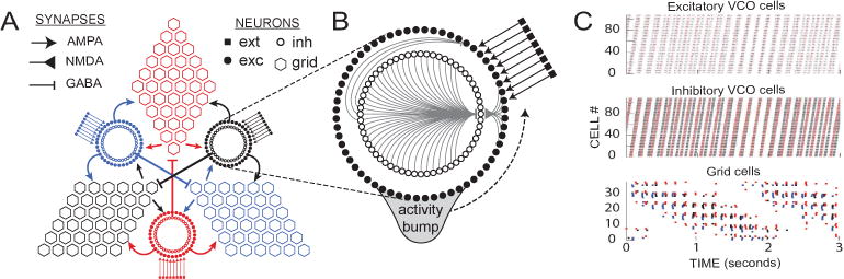
Circuit architecture. A) The model circuit consists of three sheets of grid cells, reciprocally connected with three VCO rings that receive driving inputs that encode movement velocity signals. The terms AMPA, NMDA, GABA indicates the types of synapses through which neurons are connected. B) Each VCO ring is composed of two circular layers of neurons, one excitatory and the other inhibitory, interconnected with one another by rotationally asymmetric weights so that an activity bump circulates around the ring in the counterclockwise direction. C) Spike rasters show propagation of the activity bump through the VCO layers (top two graphs) and the grid cell sheets (bottom graph) during a 3-second simulation of a rat running at constant speed along a linear path.
A. Compartment
A neuron compartment is the basic unit of neuron simulation, which models a section of a neuron cell as an electrical circuit illustrated in Fig. 2. In the circuit, a series of synaptic channels modeled by a reversal potential E and conductances g are connected in parallel with the membrane voltage Vm and the membrane capacitance Cm. The electrical circuit is simulated by numerical integration with the forward Euler method.
Fig. 2.
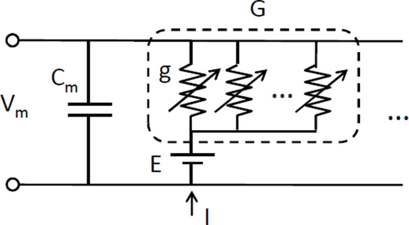
Circuit model of IAF neuron.
The synaptic channels receive the spiking stimulus from pre-synaptic neurons that changes their conductances. As a result, the membrane voltage will increase or decrease based on the activation of synaptic channel and the driving force. If a synapse decreases the membrane voltage, it is called an inhibitory neuron, while if the neuron increases the membrane voltage, it is called an excitatory neuron.
The synaptic conductances obey first-order kinetics, and are updated at each time step by numerical integration as follows:
| (1) |
where g(t) is the channel conductance at time step t, and the decay of conductance is modeled as time constant τα. The strength for each type of synapse is scaled by A, and the spiking event is modeled with a delta function where δ(t) ≠ 0 when a pre-synaptic spike is fired at time step t.
Eq. 1 describes the basic model for AMPA and GABA synapses. The kinetics model for NMDA synapses is slightly different, but it is mapped to our platform in the same way. Therefore, we do not elaborate this level of detail in this paper.
B. Cell
A neuron cell contains one or more compartments. In the case of the oscillatory neural microcircuit, all cells are modeled with single-compartment.
In the IAF neuron model, a neuron spikes when Vm reaches a certain threshold Vthresh; after spiking, Vm is held at a fixed reset potential, Vreset for a certain period, which is called the post-spike refractory period. The refractory period is updated each time step by:
| (2) |
where Vthresh is the spike threshold and Trefract is the number of the time steps in the refractory period.
After the refractory period, Vm is updated by numeric integration using the Forward Euler method:
| (3) |
where t is the simulation time step, Iin and Iout are the total inward (excitatory) and outward (inhibitory) membrane currents. λ here is the constant value that models the membrane capacitance Cm and time step dt.
The membrane current Iin and Iout is the sum of currents i of each channel, which is computed as the product of a channel conductance g, and driving force D.
| (4) |
The driving forces are computed based on the membrane voltages and the reversal potentials of each channel.
C. Population
A neuron population is a group of neurons that share the same cell model and regular structured connections. In neuron simulations, having such an intermediate layer is important for efficiency.
As established in the previous section, for each synapse there will be a corresponding channel in the post-synaptic neuron, with a reversal potential and conductance. It is very costly to keep track of all these state variables, especially when neurons often have a large fan-in. For example, in the oscillatory path integration circuit a grid cell has about 600 synapses. However, when a group of neurons share the same type of synaptic channel, it is possible to combine these separate state variables into one.
When neurons in a population are connected to all neurons in another population, the synaptic channels for those connections in a post-synaptic neuron can be represented as a population conductance G(t), which is the weighted sum over corresponding conductances.
| (5) |
where i indexes the neuron in the post-synaptic population, and j indexes neurons in the pre-synaptic population. ωi,j is the synaptic weight coefficient representing the strength of the connection between neuron i and j.
With the aggregation of synaptic channels, the amount of computation to simulate a population can also be reduced because only spiking neurons will change the activities of connected neurons. This observation can be made from combining Eq. 1 with Eq. 5.
| (6) |
The first two terms of Eq. 6 represent a decay of the conductance, while the third term represents a spiking stimulus, where is the summation over all spiked neurons in the pre-synaptic population at time step t.
The weights (ωi,j) can also be aggregated as weight vectors of predefined values. In the case of the oscillatory neural microcircuits, the weight vector is defined by a Gaussian distribution [16].
| (7) |
where C is a normalizing factor, and θ * (i — j) represents the phase difference between neuron i and j in respect to the VCO ring structure.
As will be shown in Section III, our platform exploits all these properties of neuron populations to generate efficient simulation engines.
D. Circuit
A neural circuit is a collection of one or more neuron populations that can produce particular spiking patterns. Creating neuron populations and connecting them in a certain way to create circuits that generate required spiking patterns is the basic task of neuron modelers. Therefore, for a hardware accelerator platform performing neuron simulation, it is important to provide flexibility to both the neuron diversity and connectivity.
An example model of the oscillatory neural microcircuits is illustrated in Fig. 1. The whole module is connected by two types of circuits: VCO rings and grid sheets. Each VCO ring includes two populations of neurons: inhibitory neurons (inh) and excitatory neurons (exc). These two populations of neurons are interconnected with each other, and the inhibitory layer is reciprocally connected to itself. The excitatory population also receives external excitatory spike input from velocity cells (ext). The connections from inhibitory to excitatory cells are asymmetric, so that the neurons in the VCO ring fire sequentially as a ‘bump’ of spiking activity circulates around the ring at a certain frequency [8], [10], [16]. Each grid sheet includes one population of grid cells (grid) that connects to three VCO rings by receiving excitatory and inhibitory spikes from the neurons at different angular positions in those rings.
III. Platform-Based FPGA Implementation
In this section we present our platform-based FPGA simulation engine design that maps different levels of neuron models to hardware implementations. We first describe the mapping of different levels of neural microcircuits in detail. Then, with the example of oscillatory path integration, we discuss the specific optimizations that are enabled by our platform.
Fig. 3 illustrates the mapping between a neural microcircuit and the FPGA implementation with our platform. The mapping is described in a high-level XML file, in which domain experts specify the types of synaptic channels in each cell, the spiking neuron model, the populations, and the synaptic connections between the populations. Then the XML description is used to generate C code specified to FPGA implementation, and the C code will be synthesized into RTL using high-level synthesis tools. Performance tuning parameters such as loop unrolling factors can be expressed on the high-level XML description. For FPGA design experts, design optimizations can also be explored on the C level.
Fig. 3.
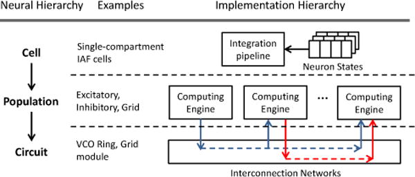
The mapping of the neural microcircuit to our platform. The left side of the figure illustrates the hierarchies of the neural microcircuit and the examples of each level in the oscillatory model. The right side illustrates the corresponding implementation in our platform-based approach.
A. Mapping Neuron Compartments and Cells
In our platform, neuron compartments are modeled with a spiking model and a synapse model. The spiking model describes the integration of membrane voltages (Vm) of each compartment. A spiking mechanism such as the IAF model is also defined in the cell model in our platform. The synapse model describes the integration of synaptic conductances G. Both multiple-compartment cells and single-compartment cells can be modeled using the same electrical circuit model in Fig. 2.
The following XML code is an example of describing a single-compartment neuron cell with the basic spiking model. Based on the definition of the cell type, which in this piece of code is IAF, our platform generates integration operations based on the biological model described by Eq. 2 and Eq. 3 from pre-defined templates. The property tags vreset, vthresh and trefract configure Vreset, Vthresh and Trefract respectively. This description in the example assumes that “iafreset”, “iafthresh” and “rstep_exc” will be defined by the user after the C code for high-level synthesis is generated, which is the same goes for the examples afterwards.
<cell type=‘IAF’>
 <vreset>iafreset</vreset>
 <vthresh>iafthresh</vthresh>
 <trefract>rstep_exc</trefrac>
</cell>
The synaptic channels in each compartment are modeled by describing a syapse on the population level. The code below shows the description of a GABA synapse called inhexc. By defining a synapse, our platform creates a synaptic conductance in the post-synaptic population, and a connection between the pre-synaptic and post-synaptic population. Our platform supports the basic types of synapses (AMPA, NMDA, GABA) by having templates for the specific types of integration operations used to model these synapses.
<synapse name=‘inhexc’>
 <pre>inh</pre>
 <type E=‘egaba’ A=‘4096’ tau=‘tau_gaba’>GABA</type>
 <weights>FUNC</weights>
</synapse>
In our platform, we define the synapses in the post-synaptic population, while the tag <pre> in the synapse description indicates the pre-synaptic population. Tag <type> indicates the specific update routine of this synaptic channel, and <weights> specifies the type of weight models that represent the strength of the synapse. This will be elaborated in the next section.
B. Mapping Neuron Populations
As described in Section II-C, the definition of neuron populations enables a variety of simplifications for simulation. Our platform exploits these simplifications by mapping a neuron population to a computation engine that contains two update pipelines: a conductance update pipeline and a membrane voltage update pipeline. In the pipelines, state variables of each neuron are integrated iteratively. An outline design of the computing engine structure is illustrated in Fig. 4.
Fig. 4.
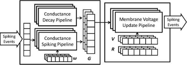
Template for computing engine of a neuron population
The conductance update pipeline integrates synaptic conductances based on the synapse model described in Section III-A. The pipeline can be divided into two stages—a decay stage that is irrelevant to the spiking input, and a spiking stage that is only activated when there is a spike input. Such a division follows the description in Eq. 6, where the spiking stage calculates the weighted sum over stimulus generated from the spiking neurons.
The weights ωi,j in Eq. 6 are modeled as weight vectors between two populations. Our platform supports four kinds of weight vectors:
Constant weights, where all ωi,j are constant for postsynaptic neuron i
- Direct functional weight mapping, where the weight values depend on the simple distance between the the two neurons i and j
(8) - Indirect functional weight mapping, where the weight values depend on the distance of neuron i and j that is defined in a distance vector
(9) Direct mapping, where a separate weight is defined for each pair of neurons.
The following code snippet shows an example of the description of a population that is named as exc and has a size of 120 neurons.
<population name=‘exc’ size=‘120’>
 <cell type=‘IAF’>
  …
 </cell>
 <synapse name=‘inhexc’>
  …
 </synapse>
 <synapse name=‘ext’>
  …
 </synapse>
</population>
In the computing engine, neuron local states are stored in memory blocks (BRAM of FPGA), and by default the two update pipelines integrate each neuron sequentially. For all the update pipelines in the template, the Initiation Interval (II) is optimized to 1, so that optimal throughput is achieved. To further improve performance, our platform also supports unrolling of the pipelines, which means neurons in a population can be updated in parallel by a certain factor. The developer can specify such factor in the <population> tag, and our platform will partition the corresponding memory blocks automatically based on the specification. The loop pipelining and unrolling is implemented by using pragmas in the Xilinx Vivado HLS tool.
C. Mapping Neural Microcircuits
In the previous subsection we introduced the computing engine and its basic structure. Here, we focus on the mapping between system-level composition of neural microcircuits and the interconnection of computing engines in our platform.
<circuit name=‘vcoring’ num_popl=‘2’>
 <population name=‘exc’ size=‘120’>
  …
 </population>
 <population name=‘inh’ size=‘120’>
  …
 </population>
</circuit>
The code snippet above shows an example of the circuit called vcoring, containing two populations: exc and inh. With the circuit structure described in the XML file, our platform generates C code for each computing engine. The connections between pre-synaptic populations and post-synaptic populations are defined by each synapse description, with which our platform generates the system-level interconnections between the computing engines. The platform also generates a top module that includes the necessary interfaces.
On the system level, our platform simulate neuron populations synchronously. That is, all computing engines synchronize at each time step. In each time step, all computing engines perform the conductance update first, and then the voltage update pipeline can integrate the membrane voltages and generate spiking events. After all spiking events of each population have been generated, the simulation proceeds to the next time step so that the spiking events can be used in the conductance update pipelines. This approach is based on the Forward Euler integration algorithm used by our simulation. In this paper, we do not explore other integration methods, since the Forward Euler is one of the simplest and most popular algorithm used by neural modelers.
D. Case Study: Oscillatory Neural Microcircuits
In this section we discuss the implementation of the oscillatory neural microcircuit based on our platform design as case study. We start from the description of a single VCO ring, which is one of the components in the oscillatory neural microcircuit. Following the description in Section II-D, the inh and exc populations are connected by NMDA and GABA synapses, and the weights are modeled as Gaussian distribution in Eq. 7. Therefore, we use the direct functional mapping to describe the weight vectors in our platform. The exc population also receives external excitatory signals as a Poisson spike train through AMPA synapses, which is modeled with a random number generator in the conductance update pipeline, and the weight vector type is constant. The XML description of a VCO ring circuit based on our platform is already introduced as examples previously in this section.
The full grid module of the oscillatory neural microcircuit is composed of two types of circuits: VCO rings and grid sheets. Besides the exc and inh populations that form the VCO ring, there is another type of population called grid that forms the grid sheets. The circuit contains nine populations in total. To describe the circuit in our platform, the user just need to define the nine populations with the basic cell type and the synapses describing the connections. The IAF model used in all populations and the three types of synapses (AMPA, GABA and NMDA) are supported in our platform by templates. We use indirect functional mapping to model the weight vectors for synapses between neurons in the VCO rings and neurons in the grid sheets.
As described in Section III-B, performance of the simulation engine can be improved by defining unrolling factors for each population. For the VCO ring, the choice is straightforward because the two populations have the same size. Therefore, the performance will increase by unrolling the two populations with the same factor. We presents the experimental results for one VCO ring in Section IV-A. For the full grid module, on the other hand, design choices become more complicated. Based on the performance bottleneck of the implementation, decisions of unrolling which population have different impacts on the performance. We show the discussion on the design space exploration and optimization in Section IV-B.
We also briefly discuss the scalability of our platform with the calculation of the bandwidth requirement of the oscillatory neural model in this section. As illustrated in Figure 1, each VCO ring is connected to two adjacent grid sheets with excitatory links, and to the other grid sheet with an inhibitory synaptic link. The oscillatory neural microcircuit is scaled up by adding the VCO ring and grid sheet in pairs. Because the role of the grid sheets is to detect synchrony between two VCO rings, the number of total connections grows linearly to the number of rings and grid sheets. Assuming 32 bits are used to index the location of each fired neuron, which is more than enough for most neural microcircuits, the bandwidth requirement for each link between computing engines is:
| (10) |
where B is the bandwidth in Byte/second, N is the number of neurons mapped to the computing engine, α stands for the firing rate, and ts is the simulation time step. Based on the equation, the roughly estimated bandwidth requirement for a single link is 2MB/s with firing rate of 10%, which is a loose upper bound for most neural circuits. The aggregated bandwidth for the entire microcircuit is around 30MB/s.
In our platform-based approach, the performance of each computing engine depends on the number of neurons in the simulated population and the firing rate of neurons in its connected computing engines. The number of connections between two populations does not grow as the model scales up. So the overall system performance is roughly proportional to the number of neurons in the system. Therefore, the performance is scalable by adding computing engines to the system such that the number of neurons mapped to each computing engine remains the same. Therefore, When the computing engines need to be mapped to multiple chips, the inter-chip connection bandwidth should not be a performance bottleneck.
IV. Experimental Results
In this section we demonstrate the performance of our FPGA simulation engine for neural circuits that perform oscillatory path integration. The results show that our platform-based approach is capable of simulating a range of different neuron models with good performance. The FPGA implementation based on our platform achieves up to 39× and 264× speedup compared to the Intel CPU and embedded ARM A9 processor respectively. We also analyze the energy-efficiency of our platform in comparison with CPU and ARM, as well as a selection of existing implementations. Compared to pure software implementation on an embedded ARM core, our platform achieves 232× energy reduction.
The CPU benchmark is the original sequential code used in oscillatory path integrator simulation, and was measured on an Intel Xeon L5408 CPU. The embedded CPU experiments were used on an ARM A9 core in a Xilinx Zynq-7045 SoC chip. The FPGA platforms for our hardware simulation evaluation is the Zynq-7045 (xc7z045ffg900-2) FPGA running at 100MHz clock.
A. Case Study: One VCO ring
We first present the performance evaluation of our computing engine design with the simulation of a single VCO ring. In the experiments, each of the two neuron populations (inh and exc) consists of 120 IAF neurons. In total, one VCO ring has 240 IAF neurons and 43,200 synapses.
In Table I, the performance of simulation engines generated by our platform with different unrolling factors is presented. The symbol “[i:j]” indicates the unrolling factors for the computing engines for inh and exc respectively. For instance, “FPGA [4:4]” represents the implementation in which the inh and exc computing engines are unrolled for four times. As described in Section III-B, the unrolling factor can be defined in each population. Since the two populations of the VCO ring has the same amount of neurons, we always unroll the two population with the same factor. The CPU and ARM performance is measured as single-thread software implementations.
TABLE I.
Performance of one-second simulation of a single VCO Ring
| Platform | Time | Speedup |
|---|---|---|
| CPU | 0.65s | 1 |
| ARM | 6.65s | 0.1× |
| FPGA [1:1] | 0.137s | 4.7× |
| FPGA [2:2] | 0.084s | 7.7× |
| FPGA [4:4] | 0.057s | 11× |
Table II shows the trade-off between the resource usage and performance for designs with different unrolling factors.
TABLE II.
Resource usage of FPGA Implementations of one VCO Ring
| BRAM | FF | LUT | Speedup | |
|---|---|---|---|---|
| FPGA [1:1] | 18 | 4.9k | 5.3k | 4.7× |
| FPGA [2:2] | 40 | 11.7k | 12.5k | 7.7× |
| FPGA [4:4] | 78 | 16.2k | 18.5k | 11× |
B. Case Study: Oscillatory Grid Module
In this section we discuss the performance of the grid module simulation. The experiments are conducted with the configuration that each population in the VCO ring contains 108 neurons, and each grid sheet contains 16 neurons. In total, the grid module contains 756 neurons interconnected by 174,960 synapses.
Because of the heterogeneity of the three populations, design choices can be made on unrolling different computing engines. Intuitively, computing engines that simulate the grid population is not the performance bottleneck, since it has far less neurons than the populations in the VCO rings. We discuss the decisions on optimizing performance in Table III. The symbol “[i:j:k]” for FPGA implementation indicates the unrolling factors for the computing engines for inh, exc and grid respectively. For instance, “FPGA [4:4:2]” represents the design in which the computing engines for inh and exc are unrolled with a factor of 4, while the computing engines for grid are unrolled with a factor of 2.
TABLE III.
Performance of one-second-simulation of the Grid Module
| Platform | Time | Speedup |
|---|---|---|
| CPU | 3.69s | 1 |
| ARM | 24.83s | 0.15× |
| FPGA [1:1:1] | 0.142s | 26× |
| FPGA [2:2:1] | 0.105s | 35× |
| FPGA [4:4:1] | 0.101s | 36.5× |
| FPGA [4:4:2] | 0.094s | 39× |
The results in Table III shows that the performance increases with larger unrolling factors of the populations in the VCO rings. However, the performance increase becomes small when reaching “FPGA [4:4:1]”. That is because the after the simulation of the VCO rings become faster, the grids becomes the performance bottleneck. Therefore, in “FPGA [4:4:2]” the performace increases when the grid is unrolled for two times.
In Table IV we present the resource usage for different implementations. The resource almost doubles when the VCO rings are being unrolled, since the computing engines for inh and exc are considerably larger than grid. Design choices can be made based on the trade-offs between performance and resource.
TABLE IV.
Resource usage of FPGA Implementations of the Grid Module
| BRAM | FF | LUT | Speedup | |
|---|---|---|---|---|
| FPGA [1:1:1] | 57 | 15.4k | 17.1k | 26× |
| FPGA [2:2:1] | 86 | 37.7k | 35.8k | 35× |
| FPGA [4:4:1] | 145 | 74.9k | 70.2k | 36.5× |
| FPGA [4:4:2] | 148 | 78.0k | 73.0k | 39× |
C. Energy Consumption Estimation
In this section we compare the energy performance of our FPGA simulation engine with other established implementations. First, we define the metric that will be used to evaluate energy consumption. Since the existing work implements different neuron models, it is unfair to compare the overall power of the simulation. One plausible metric can be the unit energy consumption for a single spiking. Such a metric can be found in [17], [18].
We first look at the energy consumption of the highperformance clusters. IBM did not provide the energy statistic for their BlueGene simulator [19]. Nevertheless, [18] provides an estimate that it “consumes 655kW to simulate 1.6 · 109 neurons at the speed of 643 second per Hz.” So the energy per spiking-event is 655 · 103 ∗643/(1.6 · 109) = 263.6mJ/s.e. The SpiNNaker system, which uses a multicore ARM system with customized interconnection, consumes 43nJ/s.e. [18]. On the other end, IBM’s crossbar-based ASIC implementation consumes 45pJ/s.e. [17].
Our energy per spiking-event can be derived using the overall power consumed to simulate one second of neuron behavior and the average spike-rate per second. The implementation we used in this experiment is the grid module design “FPGA [4:4:2]”. The spike-rate is measured from simulation, which is about 120k spikes for the entire grid module in a one-second simulation. The energy consumption of CPU is estimated by operating power (40W for Xeon L5408, 10W for one core) times the simulation time. The power of ARM and FPGA implementation is recorded using the Texas Instrument Fusion Technology, which monitors real-time voltage and current data using the power buses on our Xilinx ZC706 board. Table V shows the energy per spiking-event statistics for the implementation of the Oscillatory Grid Module.
TABLE V.
Energy Estimation of Simulating Grid Module on Different Platforms
| Platform | Total Energy | Energy per Spiking-event |
|---|---|---|
| CPU | 36.9 J | 0.308mJ/s.e. |
| ARM | 8.03 J | 66.9μJ/s.e. |
| FPGA | 34.5mJ | 0.288μJ/s.e. |
Since the ARM core in the Zynq chip does not turn off when idle, the energy measurement for FPGA includes the energy cost of the ARM core as well. However, with the considerable performance improvement of hardware acceleration, our platform-based implementation still achieves 232x less energy than the embedded solution based on ARM.
V. Related Work
Neuron models, such as the integration-and-fire (IAF) model [20] and Izhikevich model [21] have been widely used for neuron simulation. These models often convey more biologically realistic information; thus the computation complexity is considerably large. Consequently, many systems use high-performance computer clusters to cope with this computing demand [22], [23]. One of the largest-scale projects, IBM’s SyNAPSE, can offer the computing power to simulate as many as 109 neurons [19]. Yet its high energy budget and availability is limited for most neuroscience research facilities.
As a result, neuron simulation has emerged as a popular domain for hardware acceleration. GPU acceleration has been explored by many previous work [24]–[26]. Although GPU offers great floating point computing power with massive parallelism, it is not an ideal architecture for neuron simulation. As pointed out in [25], for most spiking neuron models, the ratio between floating-point operation and memory operation is very small. GPU’s advantages become obvious only when using very complex neuron models. Since each neuron connects to many of its neighboring neurons, the dense communication between neurons is the biggest challenge for hardware implementation. Existing general-purposed multicore systems are also not well designed for this domain.
Recognizing this challenge, many researchers began to extract further performance and energy-efficiency improvement through customization. The SpiNNaker project combines a general-purposed multicore ARM system with customized interconnection, and offers great improvement in energy efficiency [27], [28] compared to large-scale HPC implementation. However, using general-purposed cores as computing units for neuron simulation is still not efficient, especially when neuron simulation often consists of very simple operations with limited precision.
Customized hardware can offer even higher energy-efficiency. One approach is to use a fully customized ASIC design [17], [29]. IBM’s TrueNorth architecture [29] proposes a crossbar-based implementation on ASIC and a corresponding scalable simulator. Although they provide some impressive energy results from their ASIC chip and large-scale validation from their simulator, one can argue that the crossbar design is still limited since neurons often have a very large range of fan-in and fan-out numbers.
VI. Conclusion
In this work we propose a platform-based methodology for the domain of neuron simulation. We discuss the hierarchical structure of neural microcircuits and demonstrate the mapping to digital logic using a high-level synthesis approach. Using the neural microcircuits related to oscillatory path integration as a case study, we show that our platform is significantly faster and more energy-efficient than general-purposed processors. Our platform enables domain experts to create efficient and scalable FPGA simulation engines without in-depth knowledge of hardware design. For hardware design experts, our platform also provides opportunities to conduct design space exploration with high-level synthesis tools to further optimize performance.
In the future, we are going to explore a broader design space of FPGA neuron simulation. We are especially going to focus on efficient and scalable customized network architectures, since this is one of the biggest challenges to the design of large-scale hardware simulation engine for neural microcircuits. We will also further demonstrate the benefits of our platform by designing a multi-FPGA oscillatory path integrator for larger-scale simulation, and for navigation in robotic systems. Ultimately, we believe that with our platform, neuroscientists can synthesize efficient simulation engines on FPGA, and FPGA can become one of the most favorable architectures for neuron simulation.
Acknowledgments
This work is supported by the Center for Domain-Specific Computing (CDSC) funded by NSF’s “Expeditions in Computing” award 0926127, and in part by C-FAR, one of the six centers of STARnet, a Semiconductor Research Corporation program sponsored by MARCO and DARPA. It is also supported by R01 grant MH079511.
Contributor Information
Hugh T. Blair, Department of Psychology, University of California, Los Angeles, Los Angeles, California 90095
Jason Cong, Computer Science Department, University of California, Los Angeles, Los Angeles, California 90095.
Di Wu, Email: allwu@cs.ucla.edu, Computer Science Department, University of California, Los Angeles, Los Angeles, California 90095.
References
- 1.Rice KL, Bhuiyan MA, Taha TM, Vutsinas CN, Smith MC. 2009 International Conference on Reconfigurable Computing and FPGAs (ReConFig) IEEE; 2009. FPGA Implementation of Izhikevich Spiking Neural Networks for Character Recognition; pp. 451–456. [Google Scholar]
- 2.Thomas D, Luk W. Field Programmable Custom Computing Machines, 2009. FCCM’09. 17th IEEE Symposium on. IEEE; 2009. Fpga accelerated simulation of biologically plausible spiking neural networks; pp. 45–52. [Google Scholar]
- 3.Caron L, Mailhot F. FPGA implementation of a spiking neural network for pattern matching. Circuits and Systems (ISCAS) 2011 [Google Scholar]
- 4.Cassidy A, Andreou A, Georgiou J. Design of a one million neuron single fpga neuromorphic system for real-time multimodal scene analysis. 2011:1–6. [Google Scholar]
- 5.Cong J, Liu B, Neuendorffer S, Noguera J, Vissers K, Zhang Z. High-level synthesis for fpgas: From prototyping to deployment. Computer-Aided Design of Integrated Circuits and Systems, IEEE Transactions on. 2011;30(4):473–491. [Google Scholar]
- 6.“Xilinx vivado hls.” [Online] Available: http://www.xilinx.com/products/design-tools/ise-design-suite/index.htm.
- 7.Burgess N, Barry C, O’Keefe J. An oscillatory interference model of grid cell firing. Hippocampus. 2007;17(9):801–812. doi: 10.1002/hipo.20327. [DOI] [PMC free article] [PubMed] [Google Scholar]
- 8.Blair H, Welday A, Zhang K. Scale-invariant memory representations emerge from moire interference between grid fields that produce theta oscillations: a computational model. The Journal of neuroscience. 2007;27(12):3211–3229. doi: 10.1523/JNEUROSCI.4724-06.2007. [DOI] [PMC free article] [PubMed] [Google Scholar]
- 9.Giocomo L, Zilli E, Fransén E, Hasselmo M. Temporal frequency of subthreshold oscillations scales with entorhinal grid cell field spacing. Science. 2007;315(5819):1719–1722. doi: 10.1126/science.1139207. [DOI] [PMC free article] [PubMed] [Google Scholar]
- 10.Welday A, Shlifer I, Bloom M, Zhang K, Blair H. Cosine directional tuning of theta cell burst frequencies: evidence for spatial coding by oscillatory interference. The Journal of Neuroscience. 2011;31(45):16 157–16 176. doi: 10.1523/JNEUROSCI.0712-11.2011. [DOI] [PMC free article] [PubMed] [Google Scholar]
- 11.O’Keefe J, Dostrovsky J. The hippocampus as a spatial map: Preliminary evidence from unit activity in the freely-moving rat. Brain research. 1971 doi: 10.1016/0006-8993(71)90358-1. [DOI] [PubMed] [Google Scholar]
- 12.O’keefe J, Nadel L. The hippocampus as a cognitive map. Vol. 3 Clarendon Press Oxford; 1978. [Google Scholar]
- 13.Hafting T, Fyhn M, Molden S, Moser M, Moser E. Microstructure of a spatial map in the entorhinal cortex. Nature. 2005;436(7052):801–806. doi: 10.1038/nature03721. [DOI] [PubMed] [Google Scholar]
- 14.Solstad T, Boccara C, Kropff E, Moser M, Moser E. Representation of geometric borders in the entorhinal cortex. Science. 2008;322(5909):1865–1868. doi: 10.1126/science.1166466. [DOI] [PubMed] [Google Scholar]
- 15.Geisler C, Robbe D, Zugaro M, Sirota A, Buzsáki G. Hippocampal place cell assemblies are speed-controlled oscillators. Proceedings of the National Academy of Sciences. 2007;104(19):8149–8154. doi: 10.1073/pnas.0610121104. [DOI] [PMC free article] [PubMed] [Google Scholar]
- 16.Song P, Wang X. Angular path integration by moving hill of activity: a spiking neuron model without recurrent excitation of the head-direction system. The Journal of neuroscience. 2005;25(4):1002–1014. doi: 10.1523/JNEUROSCI.4172-04.2005. [DOI] [PMC free article] [PubMed] [Google Scholar]
- 17.Merolla P, Arthur J, Akopyan F, Imam N, Manohar R, Modha DS. 2011 IEEE Custom Integrated Circuits Conference – CICC 2011. IEEE; 2011. A Digital Neurosynaptic Core Using Embedded Crossbar Memory with 45pJ per Spike in 45nm; pp. 1–4. [Google Scholar]
- 18.Sharp T, Galluppi F, Rast A, Furber S. Power-efficient simulation of detailed cortical microcircuits on spinnaker. Journal of Neuroscience Methods. 2012 doi: 10.1016/j.jneumeth.2012.03.001. [DOI] [PubMed] [Google Scholar]
- 19.Ananthanarayanan R, Esser S, Simon H, Modha D. Proceedings of the Conference on High Performance Computing Networking, Storage and Analysis. ACM; 2009. The cat is out of the bag: cortical simulations with 10 9 neurons, 10 13 synapses; p. 63. [Google Scholar]
- 20.Gerstner W, Kistler W. Spiking neuron models: Single neurons, populations, plasticity. Cambridge university press; 2002. [Google Scholar]
- 21.Izhikevich E. Which model to use for cortical spiking neurons? Neural Networks, IEEE Transactions on. 2004;15(5):1063–1070. doi: 10.1109/TNN.2004.832719. [DOI] [PubMed] [Google Scholar]
- 22.Markram H. The blue brain project. Nature Reviews Neuroscience. 2006;7(2):153–160. doi: 10.1038/nrn1848. [DOI] [PubMed] [Google Scholar]
- 23.Izhikevich E. Simulation of large-scale brain models. 2005 [Online]. Available: http://www.izhikevich.org/human_brain_simulation/Blue_Brain.htm;
- 24.Han B, Taha TM. 2010 International Joint Conference on Neural Networks (IJCNN) IEEE; 2010. Neuromorphic Models on a GPGPU Cluster; pp. 1–8. [Google Scholar]
- 25.Pallipuram VK, Bhuiyan MA, Smith MC. 2011 Symposium on Application Accelerators in High-Performance Computing (SAAHPC) IEEE; 2011. Evaluation of GPU Architectures using Spiking Neural Networks; pp. 93–102. [Google Scholar]
- 26.Hellmich HH, Geike M, Griep P, Mahr P, Rafanelli M, Klar H. 2005 IEEE International Joint Conference on Neural Networks, 2005. IEEE; 2005. Emulation Engine for Spiking Neurons and Adaptive Synaptic Weights; pp. 3261–3266. [Google Scholar]
- 27.Sharp T, Galluppi F, Rast A, Furber S. Power-efficient simulation of detailed cortical microcircuits on SpiNNaker. Journal of Neuroscience Methods. 2012 doi: 10.1016/j.jneumeth.2012.03.001. [DOI] [PubMed] [Google Scholar]
- 28.Furber S, Lester D, Plana L, Garside J, Painkras E. Overview of the SpiNNaker System Architecture. 2012 [Google Scholar]
- 29.Preissl R, Wong T, Appuswamy R, Datta P, Flickner M, Singh R, Esser S, McQuinn E, Risk W, Simon H, et al. Compass: A scalable simulator for an architecture for cognitive computing. Proceedings of the International Conference for High Performance Computing, Networking, Storage, and Analysis (SC 2012) 2012 [Google Scholar]