

Abstract
The lack of proprioceptive feedback is a serious deficiency of current prosthetic control systems. The Osseo-Magnetic Link (OML) is a novel humeral or wrist rotation control system that could preserve proprioception. It utilizes a magnet implanted within the residual bone and sensors mounted in the prosthetic socket to detect magnetic field vectors and determine the bone's orientation. This allows the use of volitional bone rotation to control a prosthetic rotator. We evaluated the performance of the OML using a physical model of a transhumeral residual limb. A small Neodymium-Iron-Boron magnet was placed in a model humerus, inside a model upper arm. Four 3-axis Hall-effect sensors were mounted on a ring 3 cm distal to the magnet. An optimization algorithm based on Newton's method determined the position and orientation of the magnet within the model humerus under various conditions, including bone translations, interference, and magnet misalignment. The orientation of the model humerus was determined within 3° for rotations centered in the arm; an additional 6° error was found for translations 20 mm from center. Adjustments in sensor placement may reduce these errors. The results demonstrate that the OML is a feasible solution for providing prosthesis rotation control while preserving rotational proprioception.
I. Introduction
A goal in prosthetics today is to develop novel, intuitive control sources for artificial limbs. Although technological advances have provided for more sophisticated, multifunctional prostheses, the current modes of control (passive, body-powered, and myoelectric) limit their functionality. Prosthetic control has improved with the advent of microprocessor-based systems [1], sophisticated pattern recognition algorithms [2], and targeted muscle reinnervation surgery [3]. However, no current prosthesis provides proprioception—the perception of the position and orientation of one's limbs in space unaided by the visual system. The lack of proprioceptive feedback forces amputees to rely on visual input, placing a significant cognitive burden on the user and resulting in mental fatigue and operational errors [4-6]. Thus, the development of controllers that provide proprioception is imperative to enable good control of complex multifunction prostheses.
Rotation is one class of physiological motion that is well suited as an intuitive control source, due to the residual limb's anatomy and physiology. Forearm and humeral rotations are essential motions for performing functional daily tasks [7-9]. Currently, rotation of upper-limb prostheses is achieved through passive, body-powered, or myoelectric control. Passive control involves prepositioning the device with one's uninvolved hand. Body-powered control employs biscapular abduction to tension a cable attached to the prosthesis and produce a force at the rotator. Myoelectric control is based on the measurement of electromyogram (EMG) signals of agonist-antagonist muscle pairs, which are processed and used to control the velocity of the rotator. Both body-powered and myoelectric control schemes utilize muscles typically unassociated with arm rotation. Additionally, the lack of sufficient control sites requires sequential control of each degree of freedom. As a result, current rotational control is slow, unnatural, and inadequate.
The musculoskeletal system of the forearm or upper arm often remains largely intact following transradial or transhumeral amputations, thereby allowing for normal, physiological rotation of the residual bone [10]. Unfortunately, this rotation can only rarely be captured mechanically by the prosthetic socket and transferred to the prosthesis. However, a new approach, called an Osseo-Magnetic Link (OML), is proposed here to interface between the human body and a prosthesis through the implantation of a small permanent magnet into the distal residual bone of an upper-limb amputee [9]. The magnet produces a constant and predictable magnetic field, such that as the residual bone rotates within the residual limb, the distribution of the magnetic field changes at the surface of the residual limb. The magnetic field distribution also changes as the residual bone translates within the residual limb. Hall-effect sensors placed in the prosthetic socket measure the magnetic field distribution due to four degrees of freedom (one rotational and three translational) and send that information to a microprocessor to determine the residual bone orientation independently of all translations. By commanding a powered wrist or elbow rotator to match the residual bone orientation, the user's volitional rotation of the residual bone can be used as the physiologically appropriate control source for the prosthetic rotator.
A major aspect of the OML is its potential to preserve elements of proprioception—a key feature in the design of an intuitive prosthetic controller. Proprioception is a complex mechanism of the somatic sensory system, in which mechanoreceptors (e.g. muscle spindles, Golgi tendon organs, and joint receptors) sense the internal mechanical forces acting on the body, such as muscle strain and tendon tension [11]. This sensory information is relayed to the brain through afferent neural pathways, where it is used to decode limb position and orientation without visual feedback [11]. In this application, proprioception of the residual limb is retained through the mechanoreceptors and neural pathways of the most distal remaining joint (i.e. the elbow in transradial amputees or the shoulder in transhumeral amputees) and is transitively projected to the prosthesis. Because the prosthetic rotator is commanded to match the residual bone orientation, the amputee retains an awareness of the location and orientation of the prosthetic joint based on the inherent proprioception of the residual bone.
Prior investigators have proposed alternative ways of interfacing between the residual bone and the prosthesis in order to achieve intuitive rotational control, including percutaneous skeletal attachment [12], angulation osteotomies [13, 14], and artificial condyles [15]. Despite their potential, these methods have major drawbacks in transferring residual bone rotation to the prosthesis, including the necessity of major surgery, infection of percutaneous rods, loosening of implants, and skin pressure sores in high-load regions [15-17]. Additionally, medical applications of magnets and magnetic field sensing devices have been studied extensively. In 1986, Troyk et al. developed a joint-angle transducer to measure knee flexion using two implanted magnets and a Hall-effect sensor [18]. Johnson et al. expanded upon the previous work by devising a two–degree of freedom joint-angle transducer comprised of a single magnet and three sensors [19]. Although relevant to the development of the proposed system, these magnetic sensing devices cannot be implemented as rotational controllers because they are unable to detect complex motions in many degrees of freedom.
The feasibility of implanting a magnet for wrist or humeral rotation control was first investigated by Li et al. [9], who used a finite element model to examine the magnetic field vectors at 36 equally spaced nodes around the circumference of a model male upper-arm. Most importantly, they showed that the magnet orientation must be determined independent of its spatial position, due to the interdependence of the position and orientation on the magnetic fields.
In this study, we developed a proof-of-concept OML system that included an algorithm capable of determining four degrees of freedom of a permanent magnet based solely on measurements of the magnetic field. Although the proposed system can be used to control prosthetic rotators for both transhumeral and transradial amputees, we investigated a transhumeral model due to the increased challenge posed by the greater mobility of the residual bone and larger size of the residual limb. We developed an algorithm to determine the position and orientation of the implanted magnet, and tested the feasibility and performance of the OML system using a physical model. We investigated the accuracy of the estimated magnet position and orientation as well as the effects of possible disturbances such as magnetic field interference and magnet misalignment.
II. Methods
A. Algorithm Development in Simulation
An algorithm was developed to determine the position and orientation of the magnet by solving the inverse problem governed by the magnetic field dipole approximation. An error space was developed and used as the objective function searched by an optimization method.
Idealized magnetic field vectors were determined using the dipole equations. The vector valued function, D(x, y, z, β), is the resultant mapping of the four-dimensional position and orientation of a dipole magnet to the three-dimensional Cartesian magnetic field vector, from a dipole magnet at a location of x, y, z and β; denoting the Cartesian position and orientation of the dipole magnet, respectively. The error space was defined as
| (1) |
where the error space, S, is the sum-squared difference between the dipole magnetic field vector at an arbitrary position and orientation, D, and the acquired magnetic field vector, B, from the ith sensor, summed over m sensors, (i.e. four magnetic field vector sensors). This established a non-convex space with a global minimum where x, y, z and β approach the actual position and orientation of the magnet. An optimization method was used to solve the solution space iteratively, converging on the determined magnet position and orientation. In order to mitigate the effects of non-convexity and local minima, the minimization of a preliminary grid search led to the determination of an initial estimate at start-up. This initial estimate is effective because thorough modeling work showed convexity in the neighborhood of the solution, thereby permitting the optimization method to converge on the global minimum. Following start-up, the previously determined solution was used as the initial estimate in the following solution determination. If the algorithm failed to converge, the start-up grid search was repeated.
We tested the ability of two classical optimization methods—gradient descent and the Newton method [20]—to converge on a simulated magnet position and orientation. We also tested their ability to track a simulated time-space magnet trajectory. In these tests, the magnetic field was simulated using the idealized dipole equations. The methods were evaluated based on their average rotational error and their computational efficiency, measured in mega-floating point operations (MFLOPs).
B. Physical Model Design
A Cartesian coordinate system was used to describe the motion of the residual bone and implanted magnet with respect to the residual limb. The x-axis was aligned with the long axis of the upper arm, the y-axis corresponded to the medial-lateral direction, and the z-axis corresponded to the anterior-posterior direction. The coordinate system was fixed to the residual limb such that only relative motions of the residual bone were taken into account.
The physical model incorporated four degrees of freedom—three translations (x-, y-, and z-axis) and one rotation (x-axis)—neglecting the effects of the two remaining rotations. The y- and z-axis translations modeled the motion of the humerus within the soft tissue of the upper arm, while the x-axis translations represented any socket slippage or skin elasticity relative to the humerus. Rotation about the x-axis, corresponding to internal-external humeral rotation at the glenohumeral joint, was also modeled. Rotations about the y- and z-axes would be the result of small-angle deflections due to the loading of the bone rather than to joint motion. Because these deflections are generally small and can be approximated by translations, the rotations were neglected.
The transhumeral model was comprised of four components: a modeled residual upper arm, an implanted permanent magnet, a sensor array, and a prosthetic rotator (Figure 1). The residual upper arm was modeled by an acrylic cylinder with an outer diameter of 10 cm, and the residual humerus was modeled by a nylon rod with a diameter of 23 mm. These dimensions were based on an average adult male mid-upper-arm circumference of 300 mm [21] and an average adult male mid-arm bone cross-sectional area of 4.2 cm2 [22]. The residual upper-arm soft tissue was modeled as air, corresponding to the approximated magnetic permeability of biological tissue [9, 23]. The length of the residual upper arm was 200 mm—two-thirds of the average intact humeral length [9] and typical of a mid-length above-elbow amputation [24]. The residual arm model was constructed to allow independent deviations in each of the four relevant degrees of freedom. Translational measurements taken with digital calipers had a resolution of 0.01 mm and rotations measured with a rotational potentiometer were accurate to 0.05°. A Neodymium-Iron-Boron (NdFeB) cylindrical rare earth magnet with a length of 19.1 mm and a diameter of 6.35 mm was implanted 1 cm from the distal end of the model residual humerus. The magnet had a magnetic flux density of 13.2 kG (Grade N40), axial magnetization, and a titanium encasement chosen for its combination of biocompatibility and low relative permeability (μr=1.00005). Twelve single-axis linear Hall-effect sensors (A3515, Allegro Microsystems, Inc., Worcester, MA) with sensitivities of 5 mV/G and field ranges of ±500 G were custom mounted as four 3-axis sensors, equally spaced around a 40 mm diameter nylon ring. The sensor ring was positioned concentric to the modeled residual humerus 3 cm distal to its end, as would be typical of installation at the apex of a prosthetic socket (known as an “axial” sensor placement). A DC brushed motor (GM8224, Pittman, Harleysville, PA) with optical encoder was used in place of a prosthetic rotator. All data acquisition and processing were done in MATLAB (Mathworks, Natick, MA) using a 16-bit data acquisition card (USB-6218, National Instruments, Austin, TX) to interface between the system and the laptop PC.
Figure 1.
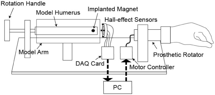
Diagram of the experimental model of a transhumeral Osseo-Magnetic Link.
C. Testing
1) Accuracy of Algorithmically Determined Magnet Position and Orientation
In order to test the system accuracy, independent error plots were generated for residual bone movements in each of the four degrees of freedom. Error was defined as the difference between the actual and algorithmically determined values. During each of the tests, a single degree of freedom was investigated while the others were held constant in a “baseline configuration.” The baseline configuration was taken to be located at (-30 mm, 0 mm, 0 mm) with 0° of rotation (note that the x-axis origin was taken in the plane of the sensors).
For pure rotation of the residual bone, position and orientation data were collected at approximately 15° intervals. For each of the three translational degrees of freedom, position and orientation data were collected every 2 mm for up to 30 mm in each direction.
The errors associated with translations along the y-axis were determined for residual bone orientations of 0° and 90°. Translations in these two orientations were chosen because they are linearly independent—one being along the axis of magnetization and the other being orthogonal to the axis of magnetization. This is the equivalent to translating the bone along the y- and z-axes while maintaining the same residual bone orientation; therefore, z-axis translations are not discussed.
For each of the four cases considered (rotation, x-axis translation, y-axis translation along axis of magnetization, y-axis translation orthogonal to axis of magnetization), the error in the calculated position is reported as the Euclidian norm of the Cartesian vector of position errors:
| (2) |
where Ex is the x-axis position error, Ey is the y-axis position error, and Ez is the z-axis position error.
2) Sensitivity to Magnetic Field Interference
The effect of magnetic field interference is a concern for any system using magnetic field sensing. To address this concern, we studied the interference effect of a DC electric motor representing a prosthetic rotator. The motor was mounted 10 mm distal to the sensor array—the closest possible mounting position—and was moved in 10 mm intervals along the positive x-axis to a maximum distance of 80 mm. The motor was powered with 9 V to mimic full-speed performance. The residual bone was set in the baseline configuration and rotated at a constant angular velocity. Data were sampled at a rate of 1 kHz. The maximum orientation error was calculated at each distance by subtracting the rotational potentiometer readings from the corresponding algorithmically determined orientation values.
Additionally, we measured interference due to external sources representative of those encountered in daily life: a bar of ferromagnetic material (steel), a power tool (120 V, 60Hz, 2A AC Dremel drill), and a permanent magnet (identical to the implanted magnet). The residual bone was set in the baseline configuration, and error in the algorithmically determined orientation was measured as a function of the distance of the object from the surface of the arm in the plane of the sensor array. Measurements were taken at 5 mm increments. The orientation of the external object played a role in the error induced in the system; therefore, the orientation causing the greatest error was used to quantify the effect of the object on the system.
3) Sensitivity to Magnet Misalignment
Unless the magnet was perfectly centered in the residual bone, any rotations would take place about an offset axis (i.e. rotation combined with translation). Therefore, we tested the system for the effects of magnet misalignment. The magnet was encased in a threaded titanium bone screw with 16 threads per inch; thus, turning the screw one revolution corresponded to a linear travel of 1.59 mm. Starting with the magnet centered in the residual bone and the bone in its baseline configuration, the screw was turned at intervals of 1/2 rotation (resulting in 0.80 mm translations). The residual bone was rotated at a constant angular velocity and the system data was sampled at a rate of 1 kHz. The maximum orientation error was calculated at each magnet-misalignment distance by subtracting the sampled rotational potentiometer readings from the corresponding algorithmically determined orientation values.
4) Sensitivity to the Earth's magnetic field
In order investigate the effect of the Earth's magnetic field, known to vary in strength between 0.3 to 0.6 G based on geographical location and sensor orientation, we determined the average magnetic sensitivity of the system using measurements of the typical field magnitudes over a rotational range of 90°. We then multiplied the average sensitivity by the maximum magnetic field experienced on the Earth's surface.
III. Results
A. Simulation Results
The optimization methods were tested with respect to the mean orientation error over the simulated trajectory, mean iterations required to converge, and the mean computational burden. As seen in Table 1, the Newton method had 5% of the error, required approximately 10% as many iterations, and the computation burden was approximately 25% of that required by gradient descent.
Table 1. Results of Optimization Methods.
| Optimization Method | Mean |Error| (SD) | Mean Iterations (SD) | Mean MFLOPs |
|---|---|---|---|
| gradient descent | 6.2° (9.0°) | 75.8 (30.3) | 75.8 |
| Newton method | 0.3° (0.3°) | 6.9 (0.9) | 18.0 |
B. Accuracy of Physical Model Magnet Position and Orientation
As the residual bone was rotated at the origin, the mean absolute value of error in the algorithmically determined orientation was approximately 1.1°, with a maximum of 3.0° and a peak-to-peak value of 5.8° (Fig. 2a). The position error was 180°-periodic, with a maximum of 2.0 mm and a minimum of 1.2 mm.
Figure 2.
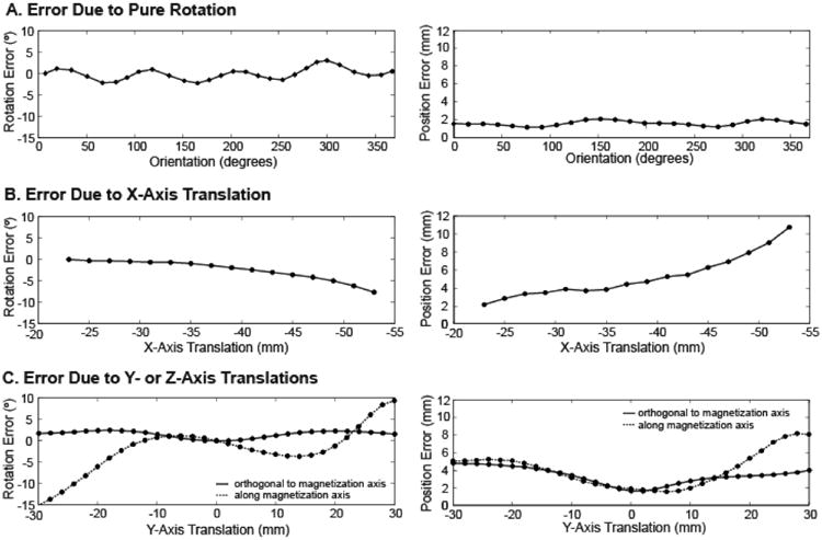
(a) Rotation error and position error as the magnet was rotated in the baseline configuration. (b) Rotation error and position error as the magnet was translated in the x-direction. (c) Rotation error and position error as the magnet was translated in the y-direction along and orthogonal to the axis of magnetization.
The accuracy of the system's determined position and orientation decreased as the magnet was translated away from the sensors along the axis of the arm (x-axis) (Fig. 2b). The maximum absolute orientation error (7.65°) and position error (10.74 mm) were measured at the maximum distance from the sensors (53 mm).
As the residual bone was translated along the y-axis orthogonal to the axis of magnetization, the algorithmically determined orientation remained within 2.5° of the actual orientation, while the magnitude of the determined position remained within 5 mm of the actual position (Fig. 2c). At 20 mm from center (the point at which the magnet passes the sensor ring), the error in determined orientation was 2.30° for positive translations and 2.40° for negative translations. Beyond 20 mm in either direction, the error in determined orientation remained stable.
For y-axis translation along the axis of magnetization, the largest errors in algorithmically determined orientation occurred at the maximum distance from the origin in either direction (9.35° at +30 mm and -15.05° at -30 mm). The error in determined orientation was 1.25° at +20 mm and 6.05° at -20 mm. However, the error in determined orientation diverged sharply beyond 20 mm from center.
C. Sensitivity to Magnetic Field Interference and Magnet Misalignment
As the distance from the DC motor to the sensor array was increased, the maximum absolute error in the rotation calculation fluctuated between 2.53° and 2.99° (Fig. 3a). This range in error is consistent with the maximum error in rotation when no motor was present (Fig. 2a). When a linear regression was performed on the data, the slope of the resulting fit line (-6.8·10-4 °/mm, R2 = 0.012) was not significantly different than zero (student t-test, p = 0.79), revealing no significant effect of the DC motor's electromagnetic interference on the rotation angle calculation.
Figure 3.
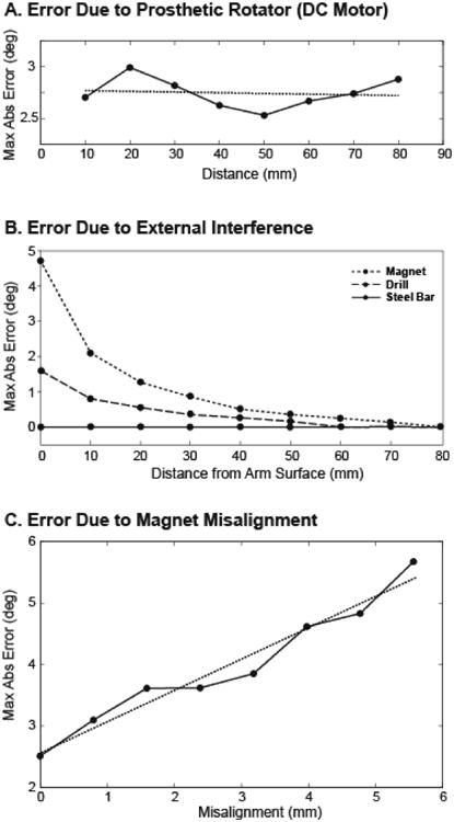
(a) Maximum absolute value of rotation error as a dc motor was translated away from the sensors. (b) Maximum absolute value of rotation error as external objects were translated away from the surface of the transhumeral model in the plane of the sensor array. (c) Maximum absolute value of rotation error as the magnet was misaligned from the bone axis, causing rotation and translation.
Of the three additional objects tested for external field interference, the permanent magnet had the largest effect on the rotation error (maximum error of 4.73° at the surface of the arm), the power drill had a smaller effect (maximum error of 1.6° at the surface of the arm), and the steel bar had no effect (Fig. 3b). At distances greater than 30 mm from the surface of the arm, no external object induced more than 1° error in the algorithmically determined orientation values, and at 80 mm from the surface of the arm, no magnetic field interference was measured due to any of the objects.
The maximum absolute rotation error measured for increasing magnet misalignment varied from 2.51° when the magnet was perfectly aligned within the residual bone to 5.67° for a 5.56 mm radial misalignment in the y-z plane (Fig. 3c). Through a regression analysis, a line was fit with a slope of 0.51 °/mm and an R2 value of 0.96. Misalignment was determined to have a significant effect on the maximum absolute error (t-test, p < 0.0001).
D. Sensitivity to the Earth's Magnetic Field
Typical field magnitudes in our model increased from 0 to 33 G over a range of 90° of bone rotation, corresponding to a system sensitivity of 0.37 G/°. Given the magnitude of the Earth's magnetic field, we calculated that it could affect the algorithmic determination by as much as 1.62°.
IV. Discussion
The aim of this study was to test the performance of an intuitive rotational controller for upper-limb prostheses. By surgically implanting a permanent magnet into the distal residual bone and measuring the magnetic field with sensors mounted in the prosthetic socket, the orientation of the residual bone could be determined and used to control a prosthetic rotator. Thus, the controller would indirectly couple the voluntary rotation of the residual bone with its physiological function of wrist or elbow rotation such that elements of proprioception remained intact. Matters of system performance, interference, and clinical implementation were considered in the assessment of the proposed system.
A. Performance
The accuracy with which the residual bone orientation can be measured determines the success of this system. While the algorithmically determined position of the bone does not have an immediate application for control, an accurate determination of all four degrees of freedom is critical to the performance of the system due to the interdependence of the position and orientation on the magnetic fields. When working under perfect conditions—a centered magnet with no external interference—the maximum system error (3° and 2 mm) was well within acceptable limits. In the worst case scenario—30 mm of y-axis translation along the axis of magnetization—the maximum system error was unacceptably high (18°). However, if the discrepancy in system accuracy between y-axis translations along the axis of magnetization and orthogonal to the axis of magnetization could be eliminated, the maximum system error without external interference would be an acceptable 5.5°.
The rotational accuracy of the proposed system was comparable to other methods for prosthesis rotation. The accuracy achieved was comparable to the performance of current body-powered rotators, which have a rotational resolution of 2° due to current locking mechanisms [9]. The resolution of externally powered rotators is not governed by the mechanical components but by the accuracy of the user's control input. The static joint angle resolution of intact humeral rotation has been reported to be 3.3°, with a dynamic resolution of 8.1° [25]. Thus, when considering the accuracy of the proposed controller in contrast to physiological resolution, we expect that the patient will perceive little difference between their voluntarily selected bone angle and the output angle of the prosthetic rotator. This continuity between the control and output angles is essential in maintaining proprioceptive awareness of the limb's orientation.
In the physiological system, the residual bone is not fixed at the center of the arm, but is able to translate within the soft tissue in what is considered the system's “workspace”—all possible bone locations as measured from the center of the bone. By subtracting the diameter of the humerus (23 mm) from that of the modeled upper arm (100 mm), the workspace for the transhumeral model was comprised of a circular area with a diameter of 77 mm. Ideally, the determination of the orientation would be independent of the position of the bone within the workspace; however, there was some observed dependence, especially beyond 20 mm translation, where the magnet passed outside the sensor ring (Fig. 2c). An investigation into the high errors generated beyond 20 mm y-axis translation revealed that the errors were caused by the break-down of the dipole approximation as the magnet approached and passed outside of the circumference of the sensor ring.
Our results indicated that by restricting the bone to a 20 mm radius workspace, the rotation error caused by bone translation could be limited to 6° (Fig. 2c). However, this area covers only 27% of the modeled workspace, and therefore does not include all of the possible magnet position and orientation combinations likely to exist. Due to the shown dependency of the error on translation outside the boundary of the sensor ring, a similar sensor configuration in the transradial case is likely to cause less error. This is primarily due to the reduction in the diameter of the residual limb, allowing the sensor ring to encompass more of the workspace. Additionally, the residual bones are less mobile in the transradial case, limiting their ability to translate outside the sensor ring. Nevertheless, we suggest the development of a new sensor configuration that prohibits the magnet from translating outside of the sensor ring. Increasing the diameter of the sensor ring would prevent this occurrence, thereby maintaining the validity of the dipole approximation and decreasing the rotation error. However, increasing the diameter of the sensor array would result in the need for a larger implanted magnet in order to maintain sufficient field strength at the sensors. For this transhumeral model, the smallest array that would contain the entire workspace would have a diameter of 77 mm. Through a computational analysis, we determined that the volume of the implanted magnet would need to be increased by 250% in order to maintain the field strength recorded by the sensors. This could be achieved by increasing the diameter of the current cylindrical magnet from 6.35 mm to 10 mm while maintaining the current length of 19.05 mm, and the magnet would still fit within the residual humerus and remain recessed within the bone. This new sensor geometry is projected to capture 100% of the workspace and eliminate the error caused by the breakdown of the dipole approximation. It is likely to have maximum errors similar to those seen at ±20 mm translation in the y-axis. Alternatively, the sensor ring could be placed circumferentially around the residual limb. This would alleviate the need to implant the magnet near the distal end of the residual bone; however, a larger magnet would be required to ensure appropriate signal strengths. A 10.6 mm diameter by 19.05 mm long cylindrical magnet would be required in this configuration and is validated by the analysis of Li, et al [26]. A more in-depth study of the applied magnetic field may lead to an optimal sensor configuration and placement.
A major clinical obstacle to our system is pistoning—relative motion between the socket and the residual arm in the axial direction, often caused by socket slippage and skin elasticity. Because the system relies on sensing the position and orientation of the magnet with respect to the socket, any pistoning would be erroneously considered residual bone motion. However, based on our results, translating the bone away from the apex of the socket would have very little effect on determining the orientation of the residual bone. Translations up to 35 mm from the sensors caused less than 1° error in the algorithmically determined orientation (Fig. 2b). Thus, a secure socket fit should ensure that pistoning does not diminish the performance of the system.
B. Interference
External magnetic fields could pose a significant risk to the viability of any electromagnetic controller. In our application, a powered prosthetic rotator would be in close proximity to the magnetic field sensors at all times. However, when testing the interference caused by a running motor, neither the motor nor its placement were found to have a significant effect on the maximum absolute error (Fig. 3a). Furthermore, external interference caused by objects likely to be encountered in daily life (ferromagnetic objects, power tools, magnets) did not appear significant enough to result in the malfunction of the OML (Fig. 3b).
It is necessary to consider the effects of the Earth's magnetic field on any system relying on magnetic field measurement. At the measured sensitivity of this system, the Earth's magnetic field can affect the rotational angle determination by as much as 1.62°, thereby causing a large portion of the system's error. This sensitivity is consistent with the 0.39 G/° sensitivity found by Li et al. [26].
C. Clinical Implementation
Several issues must be considered when analyzing the feasibility of this system as a clinical device. A major advantage is that the implantation of the orthopedic screw into the distal residual bone is a low-risk outpatient procedure. This is in contrast to the major surgical procedures required for artificial condyles, percutaneous skeletal attachment, or angulation osteotomies.
The results of this study imply that by determining both orientation and three-dimensional translation of the magnet, the effects of off-center rotations can be largely neglected. Therefore, a surgeon's ability to embed the encapsulated magnet at the center of the residual bone would only slightly affect the rotational accuracy of the system (Fig. 3c). This also means that the combined rotations and translations of the radius bone during forearm rotation would not preclude the application of this system to the transradial case.
The Osseo-Magnetic Link is intended to produce a tight coupling between rotation of the residual bone and rotation of the prosthetic device. However, the soft tissue of the arm between the bone and the prosthetic socket adds series compliance to the overall system, complicating the interaction of these rotations. This compliance has the potential to produce a mismatch between rotational values when the prosthesis interacts with an external load, creating an unstable system and affecting the patient's ability to use bone rotation as an intuitive estimate of prosthesis rotation. Because of this, care must be taken to select controller parameters that do not result in an unstable system under these circumstances. In addition, patients should be given sufficient practice in order to understand the behavior and limitations of the system. Controller tuning and patient training can occur during fitting and occupational therapy sessions with trained clinicians. In addition, adapting the system to allow nominal rotational errors would simplify the tuning procedure while still allowing improved proprioception (provided the error is less than that of the human proprioceptive threshold).
D. Future Research
The implementation of this system requires that a number of remaining issues be addressed. One important issue is the optimization of sensor placement. This study highlights some of the challenges of different sensor placement paradigms and further study is needed to identify an optimal arrangement, which may be different for different levels of amputation. Additionally, a study investigating the effects of soft tissue elasticity on system stability would provide insight and aid in clinician tuning of controller parameters. Another step towards a fully implementable system is to reduce the scale of the components so that the system can be embedded in a prosthetic device. Custom mounted sensors will also be necessary in the future system.
Acknowledgments
We would like to thank T. Walley Williams for his ideas and input to this project and Aimee Schultz and Dr. Jon Sensinger for their assistance in the preparation of this paper. This work was supported by the McCormick Foundation.
References
- 1.Lake C, Miguelez JM. Evolution of microprocessor based control systems in upper extremity prosthetics. Technology and Disability. 2003;15:63–71. [Google Scholar]
- 2.Oskoei MA, Hu H. Myoelectric control systems - a survey. Biomedical Signal Processing and Control. 2009 Feb 11;2:619–628. 2007. [Google Scholar]
- 3.Kuiken TA, Li G, Lock BA, Lipschutz RD, Miller LA, Stubblefield KA, Englehart KB. Targeted muscle reinnervation for real-time myoelectric control of multifunction artificial arms. JAMA. 2009 Feb 11;301:619–28. doi: 10.1001/jama.2009.116. [DOI] [PMC free article] [PubMed] [Google Scholar]
- 4.Simpson DC. The choice of control system for the multimovement prosthesis: Extended physiological proprioception (e. P. P) The control of upper-extremity prostheses and orthoses, P Herberts, Ed Springfield, IL: Charles Thomas. 1974:146–150. [Google Scholar]
- 5.W RF, Al-Angari HM, Heckathorne CW, Childress DS. A two degree-of-freedom microprocessor based extended physiological proprioception (E. P. P.) controller for upper limb prostheses. Technology and Disability. 2003;15:113–127. [Google Scholar]
- 6.Light CM, Chappell H, Hudgins B. Intelligent multifunction myoelectric control of hand prostheses. J Med Eng Technol. 2002;26:139–146. doi: 10.1080/03091900210142459. [DOI] [PubMed] [Google Scholar]
- 7.Atkins DJ, Heard DCY, Donovan WH. Epidemiologic overview of individuals with upper-limb los and their reported research priorities. J Prosthet Orthotics. 1996;8:2–11. 1996. [Google Scholar]
- 8.Atlas of amputations and limb deficiencies. 3rd. Rosemont: American Academy of Orthopaedic Surgeons; 2004. [Google Scholar]
- 9.Li G, Kuiken TA. Modeling of prosthetic limb rotation control by sensing rotation of residual arm bone. IEEE Trans Biomed Eng. 2008 Sep;55:2134–42. doi: 10.1109/TBME.2008.923914. [DOI] [PMC free article] [PubMed] [Google Scholar]
- 10.Neuroscience. 4th. Sunderland, MA: Sinauer Associates, Inc; 2008. [Google Scholar]
- 11.Branemark R, Branemark PI, Rydevik B, Myers RR. Osseointegration in skeletal reconstruction and rehabilitation: A review. J Rehabil Res Dev. 2001;38:175–81. 2001. [PubMed] [Google Scholar]
- 12.Branemark R, Branemark PI, Rydevik B, Myers RR. Osseointegration in skeletal reconstruction and rehabilitation: A review. Journal of Rehabilitation Research and Development. 2001;38:175–81. [PubMed] [Google Scholar]
- 13.Marquardt E, Neff G. The angulation osteotomy of above-elbow stumps. Clin Orthop Relat Res. 1974:232–238. doi: 10.1097/00003086-197410000-00027. [DOI] [PubMed] [Google Scholar]
- 14.Neusel E, Traub M, Blasius K, Marquardt E. Results of humeral stump angulation osteotomy. Arch Orthop Trauma Surg. 1997;116:263–265. doi: 10.1007/BF00390049. [DOI] [PubMed] [Google Scholar]
- 15.Witso E, Kristensen T, Benum P, Sivertsen S, Persen L, Funderud A, Magne T, Aursand HP, Aamodt A. Improved comfort and function of arm prosthesis after implantation of a humerus-t-prosthesis in trans-humeral amputees. Prosthet Orthot Int. 2006 Dec;30:270–8. doi: 10.1080/03093640600605013. [DOI] [PubMed] [Google Scholar]
- 16.von Recum AF. Applications and failure modes of percutaneous devices: A review. J Biomed Mater Res. 1984;18:323–336. doi: 10.1002/jbm.820180403. [DOI] [PubMed] [Google Scholar]
- 17.Fairley M. Osseointegration: In the wave of the future? The O&P Edge. 2006 [Google Scholar]
- 18.Troyk P, Jaeger R, Halkin M, Poyezdala J, Bajzek T. Design and implementation of an implantable goniometer. IEEE Trans Biomed Eng. 1986;33:215–222. doi: 10.1109/tbme.1986.325893. [DOI] [PubMed] [Google Scholar]
- 19.Johnson M, Hunter P, Bahdra N, Kilgore K. Implantable transducer for two-degree of freedom joint angle sensing. IEEE Trans Rehab Eng. 1999;7:349–360. doi: 10.1109/86.788471. [DOI] [PubMed] [Google Scholar]
- 20.Nocedal J, Wright S. Numerical optimization. New York: Springer Science+Business Media; 1999. [Google Scholar]
- 21.Berkow R, Beers M, Fletcher A. The merck manual of medical information. 2nd. Whitehouse Station: Merck Research Laboratories; 1997. [Google Scholar]
- 22.Heymsfield SB, McManus C, Smith J, Stevens V, Nixon DW. Anthropometric measurement of muscle mass: Revised equations for calculating bone-free arm muscle area. Am J Clin Nutr. 1982 Oct;36:680–90. doi: 10.1093/ajcn/36.4.680. [DOI] [PubMed] [Google Scholar]
- 23.Pethig R. Dielectric properties of body tissue. Clin Phys Physiol Meas. 1987;8:5–12. doi: 10.1088/0143-0815/8/4a/002. [DOI] [PubMed] [Google Scholar]
- 24.Cuccurullo SJ. Physical medicine and rehabilitation board review. New York, NY: Demos Medical Publishing, LLC; 2004. [Google Scholar]
- 25.Bevan L, Cordo P, Carlton L, Carlton M. Proprioceptive coordination of movement sequences: Discrimination of joint angle versus angular distance. J Neurophys. 1994;71:1862–1872. doi: 10.1152/jn.1994.71.5.1862. [DOI] [PubMed] [Google Scholar]
- 26.Li G, Kuiken TA. Modeling of prosthetic limb rotation control by sensing rotation of residual arm bone. IEEE Transactions on Biomedical Engineering. 2008 Sep;55:2134–42. doi: 10.1109/TBME.2008.923914. [DOI] [PMC free article] [PubMed] [Google Scholar]