Abstract
In order to probe the structure of reaction intermediates of photochemical reactions a new setup for laser-initiated time-resolved X-ray absorption (XAS) measurements has been developed. With this approach the arrival time of each photon in respect to the laser pulse is measured and therefore full kinetic information is obtained. All X-rays that reach the detector are used to measure this kinetic information and therefore the detection efficiency of this method is high. The newly developed setup is optimized for time-resolved experiments in the microsecond range for samples with relatively low metal concentration (~1mM). This setup has been applied to study a multicomponent photocatalytic system with a Co(dmgBF2)2 catalyst (dmg2− = dimethylglyoximato dianion), [Ru(bpy)3]2+ chromophore (bpy=2,2′-bipyridine) and methyl viologen as the electron relay. On the basis of analysis of hundreds of Co K-edge XAS spectra corresponding to different delay times after the laser excitation of the chromophore, the presence of a Co(I) intermediate is confirmed. The calculated X-ray transient signal for a model of Co(I) state with a 0.14 Å displacement of Co out of the dmg ligand plane and with the closest solvent molecule at a distance of 2.06 Å gives reasonable agreement with the experimental data.
1 Introduction
Development of catalysts for hydrogen evolution from water using sunlight is a challenging task of great practical importance1,2. Molecular catalysts based on coordination complexes of 3d metals3,4 and especially cobalt5 have high potential for large-scale applications, since they are earth-abundant in contrast to more robust platinum-based catalysts, that are more expensive and less abundant. The catalyst under investigation in the current contribution is Co(dmgBF2)2 (dmg2− = dimethylglyoximato dianion)6,7 (Scheme 1). Its hydrogen evolving activity in multicomponent systems in combination with different chromophores8,9,10 and in supramolecular systems8,9,11 has been investigated with several hundreds of turnovers achieved under homogeneous photocatalytic conditions in the presence of sacrificial electron donors. A few attempts have been made to improve the performance and stability by modification of Co ligands7,12,13. To fully exploit this approach and design ligands that stabilize the high energy intermediates along the catalytic pathway, detailed knowledge about the reaction mechanism is essential. Insights in the reaction mechanism can be gained on the basis of electrochemical5 and steady-state physicochemical (i.e. UV-visible or EPR) 12,14,15,16 characterization coupled with quantum chemical calculations17,18,14, but tracking of certain intermediates is possible only using time-resolved spectroscopic techniques.
Scheme 1.
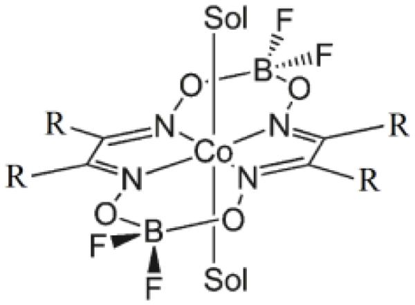
Structure of Co(dmgBF2)2 (R=methyl) and Co(dpgBF2)2 (R=phenyl). Sol is a solvent molecule (CH3CN).
The key requirements to the techniques used to identify the photocatalytic intermediates are sensitivity to the structural and electronic changes of the catalytic center, selectivity that allows to distinguish the contribution of the catalyst from all other possible changes in the complicated chemical system and appropriate time range and resolution. Stopped flow and freeze quench methods are too slow to track the intermediates of H2 evolving catalysts, especially for the most promising systems that produce hydrogen rapidly. Furthermore, since most of the reaction steps are intermolecular, the intermediates have lifetimes in the microsecond time range. Some initial reaction steps, for example, charge transfer from the chromophore to the catalytic center in the supramolecular systems can be intramolecular and occur within picoseconds19, but the charge-separated state has to be long lived to participate in the subsequent intermolecular reactions. Thus measurements in the microsecond range with sub- microsecod resolution are required for such applications.
Among time-resolved spectroscopic methods that are typically applied to study photocatalytic intermediates and reaction mechanism are transient optical absorption spectros20,21 copy and time-resolved IR22. Time-resolved X-ray absorption spectroscopy (XAS) has a few advantages in comparison with optical and IR methods. First of all XAS is element - specific and therefore the contribution from the metal center of the catalyst is separated from all other changes in the system. Second, XAS spectra contain structural information about the local arrangement of the metal (in the fine structure of the near edge X-ray absorption spectrum known as XANES) and information about the oxidation state (mainly in the position of the absorption edge). Setups for time-resolved hard X-ray absorption spectroscopy measurements with ~100 ps resolution have been developed at a few beamlines worldwide23,24,25,26,27,28 Experiments in the microsecond range are quite rare and can be performed using spatially separated laser and X-ray beams (pump-flow-probe mode)29,30 gating of the detector (pump-probe mode)31 or recording the arrival time of all photons (pump-sequential-probes mode)29,32,33,34.
Pump-flow-probe experiments use non-overlapping laser excitation and X-ray probing beams focused on the sample jet. The solution is circulating in the flow system and a cylindrical jet with a liquid speed of a few meters per second is formed. A continuous wave laser focused on the jet initiates the reaction, the distance between laser and X-ray beams and the velocity of the liquid flow determine the time delay, while the focusing of both beams defines the time resolution. The pump-flow-probe method is characterized by a high detection efficiency and the resolution is limited to ~40 μs with easily achievable flow parameters (flow speed ~ 5m/s, jet diameter ~1mm) and moderate X-ray spot size (~100 μm). Pump-probe experiments with microsecond resolution can use the same data acquisition electronics as pump-probe experiments with picosecond resolution by increasing the width of the X-ray detector gate pulse. Since many X-ray bunches delivered by the synchrotron will fall within the time window defined by such a gate pulse, the time resolution is defined by the width of this pulse. The detection efficiency of pump-probe methods also depends on the gate, its shortening corresponds to higher time resolution but lower efficiency. Acquiring kinetic data with this approach requires scanning the delay between laser and gate pulses.
In the present manuscript we report a pump-sequential-probes setup to study photocatalytic intermediates that have lifetimes in the microsecond range. This setup is realized at the SuperXAS beamline of the Swiss Light Source and described in the experimental setup section. With this approach the arrival time of each photon in respect to the laser pulse is measured (method known as time-tagged photon counting) and therefore, in contrast to currently available pump-probe setups, full kinetic information is obtained without any delay scan. In the application section we demonstrate how this method is used to identify the intermediate states of a Co(dmgBF2)2 catalyst in the multicomponent system and to probe the structure of Co(II) and Co(I) states of the catalyst in solution.
Experimental Setup
X-ray source
The pump-sequential-probe setup has been developed and implemented at the SuperXAS beamline of the Swiss Light Source (SLS), Villigen, Switzerland. X-ray beam was delivered by the 2.9T super-bend magnet. The SLS was run in the standard top-up mode with average current of 400 mA. A collimated beam was formed by means of a Si mirror and the energy has been scanned by a channel-cut Si(111) monochromator. A toroidal mirror with Rh coating was employed after the monochromator to focus the incident X-rays with a spot size of 100×100 μm2 on the sample. The photon flux obtained with this configuration at the sample was about 3.2×10¹¹ photons/s.
Laser source
For time-resolved experiments the optimal repetition rate of the laser can be chosen maximizing the efficiency of X-ray flux usage. A useful X-ray signal of the excited state is obtained first of all during the time when intermediate species are formed in the detectable amount. Since the difference between excited and unexcited spectra is measured, the system has to fully return to the initial state between laser pulses. Therefore approximately half of the laser period can be used to measure the ground state contribution. As the result, the optimal repetition rate corresponds to a few lifetimes of the studied intermediate. Nevertheless if such species live too long or if the lifetime is not known a-priori it is necessary to refresh the sample between two subsequent laser pulses. For samples in the liquid phase this can be achieved using a liquid jet flow system which is also beneficial to reduce X-ray and laser induced damage of the sample. In such configuration, the period of the laser should not be much longer than the time required to refresh the sample. The second factor that has to be taken into account is the laser pulse energy that usually decreases with increasing repetition rate and must be sufficient to efficiently excite the sample.
For our source, the maximal focusing of the X-ray beam is ~100*100 μm2. The laser spot with diameter D has to be bigger in order to probe only the volume excited efficiently and taking into account that it is difficult to achieve stable flow of the sample in the liquid jet with speed v higher than ~5m/s the maximal repetition rate f=v/D ~30 kHz is required. In our setup we used a Xiton IDOL laser with repetition rate up to 40kHz and maximal output power ~2W at 15kHz. Available wavelengths for this laser are 447 nm and 671 nm. Maximal pulse energy is 125 μJ which is more than enough to excite samples of reasonable optical density (0.2 or higher) with a metal concentration of ~1mM in an irradiated volume of ~200 μm diameter and ~1mm thickness.
Data acquisition system (DAQ)
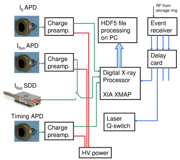
The main advantage of our DAQ is the use of so-called time-tagged single photon counting method to obtain kinetic structural information from XAS in the range between tens of nanoseconds up to hundreds of microseconds. Such an approach allows to use the flux of a bending-magnet beamline efficiently. The setup (see Fig. 1) is based on the multichannel digital X-ray processor XIA XMAP running in the so-called list mapping mode. In this regime information about each registered photon: arrival time (with respect to the trigger with a precision of 20ns) and energy is buffered and then saved to file in HDF5 format. As detectors for incoming and fluorescence radiation we used avalanche photo diodes (APDs) coupled to the charge sensitive preamplifier. An additional APD that is sensitive to the laser light is connected to one of the channels of the digital X-ray processor and provides the reference signal of the timing of the laser pulse.
Fig. 1.
Scheme of data acquisition system for pump-sequential-probe experiments
To achieve synchronization between X-rays, laser and DAQ we used the radio frequency (RF) signal from the storage ring (500 MHz) which is intrinsically synchronized with X-ray pulses. It serves as the input for the event receiver (Micro Research, VME-EVR-230RF) that divides the frequency of the RF signal and generates square pulses corresponding to the required repetition rate of the experiment. These signals are further processed with the delay card (Micro Research, 4CHTIM-200) generating pulses of required duration (2 μs for the laser trigger, 40ns for the digital X-ray processor trigger) and with required relative delay. The signal sent to the laser allows to control its acousto-optic modulator and thus to achieve synchronization between actual laser pulse and DAQ better than 2 ns. HDF5 files generated by XMAP are processed online during the incoming X-ray energy scan with a short delay (time of measurement of 1-2 energy points). Histograms with the number of events as a function of time for selected energies of fluorescent photons are calculated. Further processing such us calculation of transient spectra is performed on the basis of these data.
Synchronization
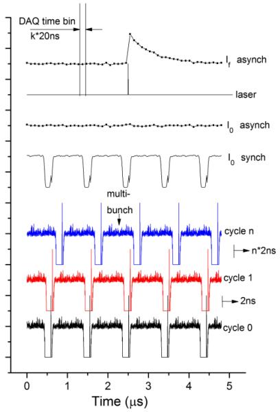
The distribution of the current in synchrotron storage rings is not uniform and at the SLS a hybrid mode is often used. 390 bunches are separated by 2ns from each other and they form the multibunch train while one additional more intense pulse, the so-called camshaft is located in the gap between multibunches (Fig. 2). While such a distribution is useful for experiments that require 100 ps time resolution correlated to the width of the camshaft pulse35, a uniform average incoming intensity distribution is preferable for microsecond and nanosecond experiments. This has been achieved by keeping the synchronization between laser and DAQ and simultaneously shifting these two triggers relatively to the filling pattern of the synchrotron. This mode of our experimental setup we call asynchronous. Schematically it is shown in Fig. 2.
Fig. 2.
Scheme of measurements using synchronous and asynchronous mode of data acquisition system. Distribution of incoming X-ray intensity as a function of time is shown for a few individual cycles and for the averaged intensity in the synchronous and asynchronous mode. Position of the laser pulse and averaged intensity for the fluorescent detector are also shown.
After each laser pulse intensity I0 and If are measured as a function of time. A spectrum with good statistics can be obtained by averaging X-ray data following at least 105 laser pulses. However if the time position of the laser pulse is fixed to the camshaft position, the I0 as a function of time would exhibit dips in intensity as shown in Fig. 2 by I0 synch. Instead, in the asynchronous mode the trigger pulses follow with the frequency so that the filling pattern of the storage ring is shifted relative to the laser pulse by 2ns (1/480 of the storage ring cycle) after each laser period. As a result measuring each point of the spectrum at least for a 10 seconds (corresponding to 104 laser cycles) one observes a uniform intensity distribution for the incoming beam as shown in Fig.2 by I0 asynch. It allows to avoid “bad time points” that correspond to the measurements of the kinetic histogram during the time between multibunches of the storage ring. Additionally, we eliminated the need of incoming intensity measurements for each time point I0(t). Only the average value I0 has to be measured. In the synchronized mode fluorescence intensity has to be normalized to the incoming intensity for each time point since bunches in the storage ring have different current. Simplification of I0 detection in the asynchronous mode has a positive impact on the signal to noise ratio of measured XAS spectra since the contribution of noise from I0 measurements becomes negligible.
Detectors
Large area avalanche photo diodes (Advanced Photonix Inc, model 630-70-72-500) with sensitive surface area 200 mm2 and sensor thickness ~400 μm were used as detectors. Rise time of signal from APD after the charge preamplifier (fastComTec, model CSP10) has been measured and it is 30-40 ns (10-90%), depending on the device. The overall time resolution of the setup (that takes into account the contribution from the finite sampling frequency of the digital X-ray processor, APD and preamplifier contributions and all other synchronization jitters) is 30 ns (FWHM) as measured with only one bunch in the storage ring. The energy resolution of APDs is 700-800 eV at 5.9 keV which is not sufficient to discriminate efficiently the elastic scattering of X-rays and sample fluorescence. Therefore we used the combination of a Z-1 filter to reduce the unwanted background from the elastically scattered photons and Soller slits with conical geometry that partially protect the detector from re-fluorescence from the Z-1 filter. The distance between slit and the sample jet was fixed at 6 mm. The geometrical parameters of the slit were optimized numerically by finding a compromise between efficiency of the slit and minimization of the distance between sample and detector. Longer slits block re-fluorescence more efficiently, but the solid angle for the detector becomes smaller. As a result we have constructed a Soller slit with 5.6 mm thickness that has an efficiency γ=0.962 (only 3.8% of re-emitted photons will find a way to the detector) and with slit transmittance of 78% (22% of useful fluorescence photons will be blocked by the slit). Our DAQ is also compatible with silicon drift detectors that have lower time resolution and area, but at the same time have higher energy resolution and therefore can be used without Z-1 filter and Soller slits.
Samples
[Ru(bpy)3]Cl2, methyl viologen dichloride (MVCl2), NH4PF6, NBu4PF6 and anhydrous acetonitrile were purchased from Sigma-Aldrich and used without further purification. As photo-sensitizer and electron-relay, [Ru(bpy)3](PF6)2 and MV(PF6)2 were prepared from NH4PF6 and [Ru(bpy)3]Cl2 or MVCl2 respectively, following a standard anion-exchange procedure. The catalyst [Co(dmgBF2)2(OH2)2] (dmg2− = dimethylglyoximato dianion) was purchased from Strem Chemicals Inc. The sample consisted of an acetonitrile solution of [Ru(bpy)3](PF6)2 (0.4 mM), MV(PF6)2 (8 mM), tetrabutylammonium hexafluorophosphate NBu4PF6 (0.1M) and [Co(dmgBF2)2(CH3CN)2] (0.8 mM) which forms spontaneously from [Co(dmgBF2)2(OH2)2] in CH3CN solution. The solid-state metal complexes were handled in air. The freshly prepared sample solution was degassed with N2 at least 30 minutes before the experiment and continuously purged and kept under N2 during the experiment.
Theoretical method
Calculations of XANES spectra were performed using the full multiple scattering approach realized in the FEFF8 code36. The self-consistent potential within the muffin-tin approximation has been calculated for the cluster with 4.9 Å radius. The energy-dependent exchange-correlation potential is obtained from the Hedin-Lundqvist approach. Cluster with the radius 4.9 Å has been also used for full multiple scattering calculations of spectra.
Application
The method has been applied for preliminary studies of the charge transfer in the multicomponent photo-catalytic system which consists of Co(dmgBF2)2 catalyst, Ru(bpy)32+ chromophore and methyl viologen (MV2+) that acts as the electron relay. This system was inspired from a similar study by Gray and coworkers using a Co(dpgBF2)2 catalyst (dpg2− = diphenylglyoximato dianion) instead of Co(dmgBF2)221. The initial Co species has a formal oxidation state of 2+. After photo-excitation of the chromophore the following reactions steps are hypothetically possible:
According to the time-resolved optical data reported for Co(dpgBF2)2 21 the catalyst in Co(III) state is formed in parallel with Co reduction at the conditions without any proton source. In most Co-based H2-evolution systems5, Co(I) species play a crucial role in the catalytic mechanism: protonation of Co(I) yields Co-hydride intermediates which are the actual active species involved in H2 evolution, either in the Co(III)-H state or in the Co(II)-H state obtained after a subsequent reducing event.
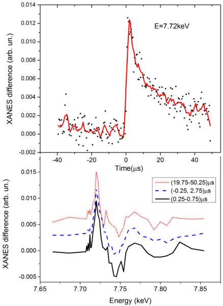
Our first goal has been the determination how many Co intermediates formed in the system. At the bottom panel of Fig. 3 we show the transient signal corresponding to different delay times between laser pump and registered X-ray photons. The width of the time window for the data corresponding to the long delay is significantly larger than for other two spectra to compensate the reduction of statistics due to the signal reduction, one can also notice that the data measured for the delay (0.25-0.75) μs is noisier than the spectrum corresponding to a six times wider (−0.25,2.75) μs time window. The amplitude of the transients has been re-normalized for easier comparison. The time-dependence of the signal monitored at fixed X-ray energy corresponding to the maximum of the transient signal is shown at the top panel of Fig. 3. Since a liquid jet with continuous flow has been used to refresh the sample between two laser pulses the slow component of the decay can be caused by the movement of the excited volume out of the probed area, while quick decay of the signal during the first 20 μs is related to the real kinetics of the system. Kinetic measurements utilizing the flow system are thus not as precise as those that one can imagine in the experiment with full exchange of the sample during the pause before each laser pulse (the repetition rate of such measurements will be extremely low). Nevertheless, the experimental spectra (bottom panel of Figure 3) measured at different time delays have very similar shapes indicating the formation of only one novel species upon irradiation of the photocatalytic system. The same result has been obtained from the analysis of the shape of the transient signals as a function of time over a set of 200 experimental spectra using the method reported in37, that indicated the presence of only 2 independent spectral components in our data corresponding to the initial species together with one intermediate species.
Fig. 3.
Top Panel: Transient XANES signal measured for fixed energy of the incoming X-ray beam (E=7.72keV) as a function of time between laser pump and X-ray probe. Bottom: Transient XANES spectra corresponding to different time windows after the laser pulse: (0.25, 0.75) μs -black line; (−0.25, 2.75) μs –blue line and (19.75, 50.25) μs red line. Amplitudes were re-normalized for better comparison.
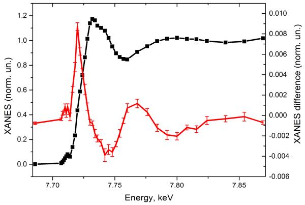
Fig. 4 shows the experimental XANES spectrum of the photocatalytic system measured before the laser pulse together with the transient spectrum that corresponds to the 10 μs time window after the laser pulse. The position of the absorption edge of the intermediate species is shifted towards lower energies with regards to the initial Co(II) (first peak of the transient signal is positive), indicative for the formation of a more reduced species, likely the Co(I) intermediate mentioned above and expected to be the entry point into a catalytic cycle for H2 evolution.
Fig. 4.
Co K-edge XANES of the multicomponent photocatalytic system with Co(dmgBF2)2 catalyst in the ground state (black line, left scale) and transient X-ray absorption spectrum (red line, right scale) that corresponds to 10 μs time window after the laser pulse.
The local structure around the metal center for molecules in solution can differ from that in the crystal phase measured using XRD and from that obtained by DFT optimization in vacuum. This is especially true for metal complexes possessing vacant coordination sites or labile ligands. Co(dmgBF2)2 belongs to this class of metal complexes and therefore we have started the simulations from the refinement of the structure of the initial Co(II) state. Both XRD38 and DFT17 structures of [Co(dmgBF2)2(CH3CN)2] have rather distant solvent molecules with bond lengths of 2.25 Å and 2.33 Å correspondingly, while some other Co(II) complexes with distorted octahedral environment and acetonitrile in the first coordination shell have significantly shorter Co-NSol bonds (2.08-2.09 Å) in the crystallized state39,40.
Therefore in addition to XRD and DFT structures we have constructed models (3) and (4) with short Co-NSol bonds (2.06 Å and 2.0 Å respectively). To take into account the expected disorder of the solvent molecules and avoid biases due to the strong multiple scattering along the Co-N-C path as found in the crystal and DFT-based structures, we have approximated the contribution of solvent to the XANES by taking into account the scattering from the nearest N atoms only.
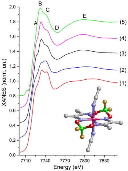
Fig. 5 shows that the agreement between the experimental spectrum and the spectra calculated for XRD (1) and DFT (2) models is not satisfactory. The relative intensity of peaks B and C is wrong. In addition, both calculated spectra display a shoulder between minimum D and maximum E that is not so well pronounced in the experimental data. Both models with short Co-NSol bonds (3 and 4) agree reasonably well with the experiment. Variation of the Co-NSol distance within these limits influences slightly on the intensity of shoulder A which is observable, but rather weak in the experimental spectrum. As additional small adjustment we have reduced the Co-Neq distances for models (3) and (4) by 0.03 Å relative to the XRD model. It has not changed the overall shape of the spectrum but has allowed to achieve better agreement in the position of minimum D.
Fig. 5.
Theoretical Co K-edge XANES spectra of [CoII(dmgBF2)2(CH3CN)2] calculated for a model obtained using either X-ray diffraction38 (red curve (1)), DFT optimization17 (blue curve (2)), a model with disordered solvent molecules with Co-NSol distances of 2.06 Å (black curve (3)) and 2.00 Å (magenta curve (4)). Curve (5) is the experimental spectrum of the multicomponent photocatalytic system with [Co(dmgBF2)2(CH3CN)2] catalyst measured before the laser pulse. The insert shows the structure of [Co(dmgBF2)2(CH3CN)2]. Grey atoms are C, red - O, blue - N, green - B, yellow - F, magenta - Co. H atoms are omitted for simplicity.
Experimentally determined reference structures for Co(I) species with glyoxime ligands are very rare in the literature. The only one available crystal structure of a Co(I) complex with 2 diphenylglyoximato ligands and acetonitrile has been reported12. Since the atomic cluster with the radius 4.9 Å has been used to calculate X-ray absorption spectra, the substitution of methyl by phenyl group does not influence significantly on the shape of XANES. According to this XRD model Co(I) is five- coordinated in a distorted square-pyramidal environment with a short Co-NSol bond 1.97 Å and 0.27 Å displacement of Co out of the plane formed by the equatorial nitrogen atoms. Acetonitrile is oriented almost perpendicular to the equatorial plane with a Co-N-C angle of 1740. Hu et al. note that “solvent molecules were severely disordered and could not be refined accurately”. The DFT optimized structure for Co(I) state reported by Muckerman and Fujita17 has a significantly different orientation of the solvent molecules. Two of them were included in this model and the authors have found that both of them are oriented by the CH3 group towards the Co atom with large Co-C distances of 3.7 Å and 4.8 Å, thus the Co atom is 4-coordinated.
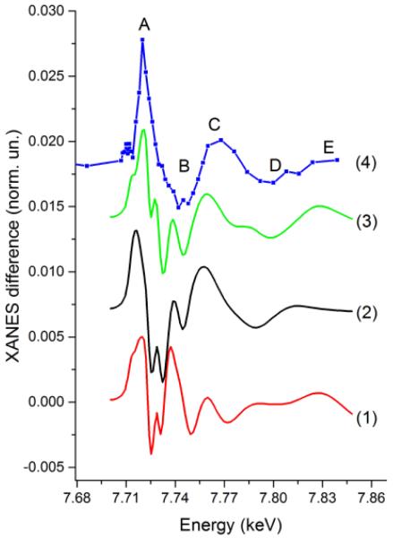
Model (3) of Co(I) intermediate has been constructed starting from the model of Co(II) species with disordered solvents (curve (3) in Fig. 5) that gave good agreement with experiment. One of the solvent molecules has been moved away from the Co center to the distance 2.18 Å, while the second CH3CN has been fixed at 2.06 Å. Additionally we have introduced moderate out of plane displacement of the Co atom (0.14 Å) and a small contraction of Co-Neq (0.02 Å) as it has been suggested in both XRD and DFT models. Fig. 6 compares theoretical transient spectra calculated for these three models with the experimental pump-probe data. In addition to the structural changes we have taken into account 1eV chemical shift of the absorption edge which is due to the movement of the core level as a result of changes of the screening by valence electrons. As one can see the shape of the transient signal is completely wrong for XRD model (1). The reason is similar to those observed also for XRD structure of the ground state Co(II) species. Strong multiple scattering from the collinear Co-N-C chain of the solvent molecule influences the XANES significantly and therefore the model that ignores the disorder of solvent molecule fixing the solvent at idealized orthogonal orientation is not realistic. The DFT model is in better agreement with the experiment. A correct overall trend of the transient spectrum is seen, but all main features are shifted in energy. Please note that even if the absolute scale of the energy calculations is not always correct we have performed already a few eV shift of the ground state spectrum and therefore there is no additional free parameter related with the independent shift of the transient spectrum. Among 3 considered structures the model (3) gives best agreement with the experiment. The theoretical spectrum is more structured between maxima A and B which can be partially due to the fact that for the ground state peak A is more visible in the theory then in the experimental spectrum. Further improvement of the theoretical model can be based on more accurate modeling of disordered solvent around the metal complex by averaging many configurations of solvent molecules, for example using the approach previously proposed41. Nevertheless on the basis of our data we can conclude that the model with disordered solvent molecules with shortest Co-NSol distance ~2.06 Å and moderate displacement of Co out of the plane formed by N atoms of dmg ligands is the most realistic while the formation of a complex with perpendicular orientation of acetonitrile molecules has not been confirmed.
Fig. 6.
Transient X-ray absorption spectrum corresponding to the transition from Co(II) to Co(I) state. Calculations for different models of Co(I) state based on XRD (red curve (1), DFT (black curve (2)) and model with moderate out of plane displacement of Co and disordered solvent molecule (green curve (3)) are compared with the experimental data for the multicomponent photocatalytic system with Co(dmgBF2)2 catalyst (blue curve 4)
Discussing the experimental results shown in Fig. 4 that are plotted with the error bars we would like to mentioned that these measurements were taken during ~11 hours and as one can see we have obtained the transient signal of very high quality. Please note that in the comparison to the supramolecular systems42,43 or simple chromophorores44,45,46 the pump-probe signal for multicomponent systems is ~10 times weaker even if we are not limited by the pulse energy of the initial photoexcitation. Nevertheless, intermediates are relatively long-lived which somehow compensates the decrease of the statistics from the reduction of the signal amplitude. The incoming intensity of X-ray radiation at the bending magnet beamline of SLS is lower than, for example, at the undulator beamlines of the APS synchrotron. Paradoxically it can be seen also as an advantage since lower intensity allows to increase the detection efficiency using the single photon counting approach and at the same time to decrease the X-ray induced damage of the sample. In our previous work on the multicomponent system with similar Co-based catalyst that has been performed at 11ID-D beamline of the APS we observed significant damage of the sample due to X-rays (incident X-ray flux ~6*1012 photons/s) while it is found negligible at the SuperXAS beamline of the SLS (flux 3*1011 photons/s)29. The number of photons registered by the fluorescence detector at the APS is around 3-4 per X-ray bunch for the samples with ~1mM concentration; therefore single photon counting is not possible and the data acquisition system works in the current mode. At SuperXAS of SLS for analogous sample we have a bit less than 1 photon/1μs and therefore single photon counting is efficient. An additional advantage of our approach that has not been used for the present application of the setup is the possibility to use energy-resolving detectors, such as silicon drift detectors, that have a resolution of ~120eV and therefore allow further increase of the signal to noise ratio for diluted samples.
Acknowledgements
L.X Chen, X. Zhang and V. Sundstrom are acknowledged for constructive discussion. This work was supported by the Swiss National Science Foundation (grant nr 200021-135226), European Commission’s Seventh Framework Programme (FP7/2007-2013) under grant agreement n.° 290605 (COFUND: PSI-FELLOW), the French National Research Agency (ANR, Labex program ARCANE, ANR-11-LABX-0003-01) and the European Research Council (ERC grant agreement n. 306398). The COST Action CM1202 PERSPECT-H2O is also acknowledged. AG would like to thank Russian Foundation for Basic Research (project #14-02-31555).
References
- 1.Thapper A, Styring S, Saracco G, Rutherford AW, Robert B, Magnuson A, Lubitz W, Llobet A, Kurz P, Holzwarth A, Fiechter S, de Groot H, Campagna S, Braun A, Bercegol H, Artero V. Green. 2013;3:43–57. [Google Scholar]
- 2.Lewis NS, Nocera DG. Proc. Natl. Acad. Sci. 2006;103:15729–15735. doi: 10.1073/pnas.0603395103. [DOI] [PMC free article] [PubMed] [Google Scholar]
- 3.Eckenhoff WT, Eisenberg R. Dalton Trans. 2012;41:13004–13021. doi: 10.1039/c2dt30823a. [DOI] [PubMed] [Google Scholar]
- 4.Thoi VS, Sun Y, Long JR, Chang CJ. Chem. Soc. Rev. 2013;42:2388–2400. doi: 10.1039/c2cs35272a. [DOI] [PubMed] [Google Scholar]
- 5.Artero V, Chavarot-Kerlidou M, Fontecave M. Angew. Chem.-Int. Ed. 2011;50:7238–7266. doi: 10.1002/anie.201007987. [DOI] [PubMed] [Google Scholar]
- 6.Baffert C, Artero V, Fontecave M. Inorg. Chem. 2007;46:1817–1824. doi: 10.1021/ic061625m. [DOI] [PubMed] [Google Scholar]
- 7.Hu X, Cossairt BM, Brunschwig BS, Lewis NS, Peters JC. Chem. Commun. 2005:4723–4725. doi: 10.1039/b509188h. [DOI] [PubMed] [Google Scholar]
- 8.Fihri A, Artero V, Pereira A, Fontecave M. Dalton Trans. 2008:5567–5569. doi: 10.1039/b812605b. [DOI] [PubMed] [Google Scholar]
- 9.Fihri A, Artero V, Razavet M, Baffert C, Leibl W, Fontecave M. Angew. Chem. Int. Ed. 2008;47:564–567. doi: 10.1002/anie.200702953. [DOI] [PubMed] [Google Scholar]
- 10.Du P, Schneider J, Luo G, Brennessel WW, Eisenberg R. Inorg. Chem. 2009;48:4952–4962. doi: 10.1021/ic900389z. [DOI] [PubMed] [Google Scholar]
- 11.Li C, Wang M, Pan J, Zhang P, Zhang R, Sun L. J. Organomet. Chem. 2009;694:2814–2819. [Google Scholar]
- 12.Hu X, Brunschwig BS, Peters JC. J. Am. Chem. Soc. 2007;129:8988–8998. doi: 10.1021/ja067876b. [DOI] [PubMed] [Google Scholar]
- 13.Zhang P, Jacques P-A, Chavarot-Kerlidou M, Wang M, Sun L, Fontecave M, Artero V. Inorg. Chem. 2012:51. doi: 10.1021/ic2019132. [DOI] [PubMed] [Google Scholar]
- 14.Bhattacharjee A, Chavarot-Kerlidou M, Andreiadis ES, Fontecave M, Field MJ, Artero V. Inorg. Chem. 2012;51:7087–7093. doi: 10.1021/ic2024204. [DOI] [PubMed] [Google Scholar]
- 15.Szajna-Fuller E, Bakac A. Eur. J. Inorg. Chem. 2010;2010:2488–2494. [Google Scholar]
- 16.Lazarides T, McCormick T, Du P, Luo G, Lindley B, Eisenberg R. J Am Chem Soc. 2011;131:9192–9194. doi: 10.1021/ja903044n. [DOI] [PubMed] [Google Scholar]
- 17.Muckerman JT, Fujita E. Chem. Commun. 2011;47:12456–12458. doi: 10.1039/c1cc15330g. [DOI] [PubMed] [Google Scholar]
- 18.Solis BH, Hammes-Schiffer S. Inorg. Chem. 2011;50:11252–11262. doi: 10.1021/ic201842v. [DOI] [PubMed] [Google Scholar]
- 19.Veldkamp BS, Han W-S, Dyar SM, Eaton SW, Ratner MA, Wasielewski MR. Energy Environ. Sci. 2013;6:1917–1928. [Google Scholar]
- 20.Dempsey JL, Winkler JR, Gray HB. J Am Chem Soc. 2011;132:16774–16776. doi: 10.1021/ja109351h. [DOI] [PubMed] [Google Scholar]
- 21.Dempsey JL, Winkler JR, Gray HB. J Am Chem Soc. 2011;132:1060–1065. doi: 10.1021/ja9080259. [DOI] [PubMed] [Google Scholar]
- 22.Probst B, Kolano C, Hamm P, Alberto R. Inorg. Chem. 2009;48:1836–1843. doi: 10.1021/ic8013255. [DOI] [PubMed] [Google Scholar]
- 23.Chen LX, Zhang X, Lockard JV, Stickrath AB, Attenkofer K, Jennings G, Liu DJ. Acta Crystallogr. A. 2010;66:240–251. doi: 10.1107/S0108767309051496. [DOI] [PubMed] [Google Scholar]
- 24.Bressler C, Chergui M. Annu. Rev. Phys. Chem. 2010;61:263–282. doi: 10.1146/annurev.physchem.012809.103353. [DOI] [PubMed] [Google Scholar]
- 25.Sato T, Nozawa S, Ichiyanagi K, Tomita A, Chollet M, Ichikawa H, Fujii H, Adachi S, Koshihara S. J. Synchrotron Radiat. 2008;16:110–115. doi: 10.1107/S0909049508034596. [DOI] [PMC free article] [PubMed] [Google Scholar]
- 26.March AM, Stickrath A, Doumy G, Kanter EP, Krässig B, Southworth SH, Attenkofer K, Kurtz CA, Chen LX, Young L. Rev. Sci. Instrum. 2011;82:073110. doi: 10.1063/1.3615245. [DOI] [PubMed] [Google Scholar]
- 27.Tromp M, Dent AJ, Headspith J, Easun TL, Sun X-Z, George MW, Mathon O, Smolentsev G, Hamilton ML, Evans J. J. Phys. Chem. B. 2013;117:7381–7387. doi: 10.1021/jp4020355. [DOI] [PMC free article] [PubMed] [Google Scholar]
- 28.Stern EA, Brewe DL, Beck KM, Heald SM, Feng Y. Phys. Scr. 2005;2005:1044. [Google Scholar]
- 29.Smolentsev G, Guda A, Zhang X, Haldrup K, Andreiadis ES, Chavarot-Kerlidou M, Canton SE, Nachtegaal M, Artero V, Sundstrom V. J. Phys. Chem. C. 2013;117:17367–17375. doi: 10.1021/jp4010554. [DOI] [PMC free article] [PubMed] [Google Scholar]
- 30.Thiel DJ, Līviņš P, Stern EA, Lewis A. Nature. 1993;362:40–43. doi: 10.1038/362040a0. [DOI] [PubMed] [Google Scholar]
- 31.Wang H, Peng G, Cramer SP. J. Electron Spectrosc. Relat. Phenom. 2005;143:1–7. [Google Scholar]
- 32.Scheuring EM, Clavin W, Wirt MD, Miller LM, Fischetti RF, Lu Y, Mahoney N, Xie A, Wu J, Chance MR. J. Phys. Chem. 1996;100:3344–3348. [Google Scholar]
- 33.Stickrath AB, Mara MW, Lockard JV, Harpham MR, Huang J, Zhang X, Attenkofer K, Chen LX. J. Phys. Chem. B. 2013;117:4705–4712. doi: 10.1021/jp3086705. [DOI] [PubMed] [Google Scholar]
- 34.Haumann M, Liebisch P, Muller C, Barra M, Grabolle M, Dau H. Science. 2005;310:1019–1021. doi: 10.1126/science.1117551. [DOI] [PubMed] [Google Scholar]
- 35.Lima FA, Milne CJ, Amarasinghe DCV, Rittmann-Frank MH, van der Veen RM, Reinhard M, Pham V-T, Karlsson S, Johnson SL, Grolimund D, Borca C, Huthwelker T, Janousch M, van Mourik F, Abela R, Chergui M. Rev. Sci. Instrum. 2011;82:063111. doi: 10.1063/1.3600616. [DOI] [PubMed] [Google Scholar]
- 36.Ankudinov AL, Ravel B, Rehr JJ, Conradson SD. Phys. Rev. B. 1998;58:7565. [Google Scholar]
- 37.Smolentsev G, Guilera G, Tromp M, Pascarelli S, Soldatov AV. J. Chem. Phys. 2009;130:174508. doi: 10.1063/1.3125940. [DOI] [PubMed] [Google Scholar]
- 38.Niklas J, Mardis KL, Rakhimov RR, Mulfort KL, Tiede DM, Poluektov OG. J. Phys. Chem. B. 2012;116:2943–2957. doi: 10.1021/jp209395n. [DOI] [PMC free article] [PubMed] [Google Scholar]
- 39.Bigi JP, Hanna TE, Harman WH, Chang A, Chang CJ. Chem. Commun. 2010;46:958–960. doi: 10.1039/b915846d. [DOI] [PubMed] [Google Scholar]
- 40.Lu CC, Bill E, Weyhermüller T, Bothe E, Wieghardt K. Inorg. Chem. 2007;46:7880–7889. doi: 10.1021/ic7008094. [DOI] [PubMed] [Google Scholar]
- 41.D’Angelo P, Roscioni OM, Chillemi G, Della Longa S, Benfatto M. J. Am. Chem. Soc. 2006;128:1853–1858. doi: 10.1021/ja0562503. [DOI] [PubMed] [Google Scholar]
- 42.Canton SE, Zhang X, Zhang J, van Driel TB, Kjaer KS, Haldrup K, Chabera P, Harlang T, Suarez-Alcantara K, Liu Y, Pérez J, Bordage A, Pápai M, Vankó G, Jennings G, Kurtz CA, Rovezzi M, Glatzel P, Smolentsev G, Uhlig J, Dohn AO, Christensen M, Galler A, Gawelda W, Bressler C, Lemke HT, Møller KB, Nielsen MM, Lomoth R, Wärnmark K, Sundström V. J. Phys. Chem. Lett. 2013;4:1972–1976. doi: 10.1021/jz401016h. [DOI] [PubMed] [Google Scholar]
- 43.Smolentsev G, Canton SE, Lockard JV, Sundstrom V, Chen LX. J. Electron Spectrosc. Relat. Phenom. 2011;184:125–128. [Google Scholar]
- 44.Gawelda W, Johnson M, de Groot FMF, Abela R, Bressler C, Chergui M. J. Am. Chem. Soc. 2006;128:5001–5009. doi: 10.1021/ja054932k. [DOI] [PubMed] [Google Scholar]
- 45.Smolentsev G, Soldatov AV, Chen LX. J. Phys. Chem. A. 2008;112:5363–5367. doi: 10.1021/jp801410a. [DOI] [PubMed] [Google Scholar]
- 46.Chen LX, Jager WJ, Jennings G, Gosztola DJ, Munkholm A, Hessler JP. Science. 2001;292:262–264. doi: 10.1126/science.1057063. [DOI] [PubMed] [Google Scholar]


