Abstract
Cell encapsulation technology is a promising strategy applicable to tissue engineering and cell therapy. Many advanced microencapsulation chips that function via multiple syringe pumps have been developed to generate mono-disperse hydrogel beads encapsulating cells. However, their operation is difficult and only trained microfluidic engineers can use them with dexterity. Hence, we propose a microfluidic manifold system, driven by a single syringe pump, which can enable the setup of automated flow sequences and generate highly mono-disperse alginate beads by minimizing disturbances to the pump pressure. The encapsulation of P19 mouse embryonic carcinoma cells and embryonic body formation are demonstrated to prove the efficiency of the proposed system.
INTRODUCTION
Microencapsulation of cells is a promising strategy for stabilizing, packaging, and protecting many types of cells, including living mammalian and bacterial cells. Many different polysaccharide materials have been used for encapsulation, including agarose,1 alginate,2 and chitosan.3 Amongst these, alginate is a well-characterized material in which many different mammalian cells have been grown. Encapsulation provides protection from the immune system and has been used as a carrier tool for many therapeutic cells.4,5 For example, this approach has allowed a range of promising therapeutic treatments for diabetes mellitus,6 hemophilia,7 cancer,8 and renal failure9 because it has potential as a sustained-release system for delivering therapeutic agents in vivo, while protecting encapsulated cells from the immune system.10 In addition, it can be used as a tool for high-throughput cell-based assays, which provide rich information needed in the fields of drug discovery, toxicity testing, genomics, proteomics, and cell biology.11–13
For the studies mentioned above, encapsulation technologies have been accomplished by conventional extrusion of droplets through a nozzle, followed by gelling in a bath containing a polymerizing agent.14 However, the minimum bead size is limited to about 200–400 μm, and the size dispersion is large, especially for small beads. Therefore, manufacturing mono-disperse alginate beads of smaller size (<200 μm) has been mainly performed using microfluidic technologies.15–22
Although previously reported microfluidic platforms could make mono-disperse and large numbers of alginate beads, many of these methods are considered cumbersome, laborious, and difficult. Careful control of two-phase working fluids with several external syringe pumps is required to achieve polymerization of mono-dispersed alginate beads, generation of desired bead sizes, or maintenance of cell viability in alginate beads. Thus, only well-trained microfluidic engineers can operate the microfluidic platforms available to date, so there is an urgent need to develop user-friendly microfluidic platforms that allow operation by non-experts. Facile and stable operation is important for massive parallel encapsulation of cells, as well as for commercialization through widespread use.
Hence, to address these issues, we suggest a manifold-based microfluidic platform, driven only by a single syringe pump, in contrast to the three or four used in previous microencapsulation systems.15–22 This study describes the design and fabrication of a manifold system and also reports the enhancement of mono-dispersity, achieving highly precise control of alginate bead size compared with that of multi-syringe systems.16 A manifold system with a single syringe synchronizes the fluctuation of several inlets, eliminates the pressure ripples that occur with multiple syringes, and consequently reduces variation in bead size. As a demonstration of cell encapsulation, we encapsulated P19 mouse embryonic carcinoma (EC) cells in mono-disperse alginate beads that supported cell growth and aggregation in three dimensions.
MATERIALS AND METHODS
Preparation of the microfluidic manifold system
Two microfluidic chips for flow control (Fig. 1(b)) and bead generation (Fig. 1(c)) were fabricated using an SU-8 fabrication method and replica molding. An SU-8 (Microchem, Newton, MA, USA) photoresist was used for the development of SU-8 microstructures. PDMS (polydimethylsiloxane; Sylgard 184; Dow Corning, Midland, MI, USA) was poured onto master molds. After curing, the PDMS replicas were peeled away from the master molds, and inlet and outlet holes were punched through the PDMS slab. The two fabricated PDMS slabs and glass cover slip were autoclaved and dried at 80 °C overnight to maintain cell viability. They were then plasma treated (PDC-001; Harrick, CA, USA) in air, and bonded together to form a closed microfluidic channel. Because the surface properties of the PDMS chip were altered from hydrophobic to hydrophilic during plasma treatment, the bead generation chip was soaked at room temperature for 2 days to recover its hydrophobic surface properties.
FIG. 1.
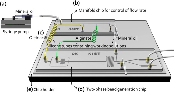
Schematic view of the microfluidic manifold platform, which was driven by a single microsyringe pump, for generating mono-dispersed beads. The microfluidic manifold platform was made up of three parts: (a) manifold chip for control of flow rates, (b) silicone tubes containing working solutions (yellow tube: calcified oleic acid as continuous fluid, green tube: alginate solution including cells, and white tube: mineral oil to remove oleic acid), and (c) two-phase bead generation chip.
Cell culture and cell viability assays
The mouse EC cell line, P19 EC, was acquired from the American Type Culture Collection (CRL1825; Manassas, VA, USA). P19 EC cells were cultured in α-MEM (Gibco), supplemented with 10% fetal bovine serum, 1% penicillin, and streptomycin (all from Gibco). P19 EC cells were maintained at 37 °C in a humidified atmosphere of 5% CO2 and passaged at 2- or 3-day intervals. Here, trypan blue was used to count live and dead cells. Cells are selective in the compounds that are able to pass through the membrane; trypan blue is not absorbed in a live cell but traverses the membrane in a dead cell. Therefore, only dead cells will show a blue color. All cell viability assays were repeated three times.
Materials preparation for cell encapsulation
Sodium alginate (A2158-250G; Sigma-Aldrich) was dissolved in culture medium (Dulbecco's Modified Eagle's Medium) to a final concentration of 2% (w/v), and a cell suspension was mixed with 1% alginate in medium. Oleic acid was used as a continuous fluid to generate the alginate droplets. The alginate was gelled by calcium infusion from the oleic acid. However, calcium chloride is only minimally soluble in oleic acid. Thus, 1.2 g of calcium chloride (C7902-500G; Sigma) was dissolved in 50 ml of 2-methyl-1-propanol (Junsei Chemical) via ultrasonication (Branson 5510). After the mixing of the calcium solution and oleic acid at a ratio of 50% (v/v), the 2-methyl-1-propanol was distilled overnight on a hotplate at 120 °C to prevent damage to the cells by alcohol. Finally, the oleic acid containing calcium was filtered with a syringe filter (0.2 μm) to remove debris. The filtered solution was then used as the calcium source for the in-channel polymerization of alginate.
The formation of embryonic bodies in alginate beads
After encapsulation using the manifold-based microfluidic platform, cell encapsulating beads were collected from an outlet-1 (Fig. 2(c)). In order to evaluate an efficiency of spherical embryonic bodies (EBs) formation with P19 EC cells in alginate beads, the cell encapsulating beads were cultured in a conventional culture dish for 2 days. When the P19 EC cells were aggregated to single spheroid, we determined that the EBs were formed.26,27
FIG. 2.
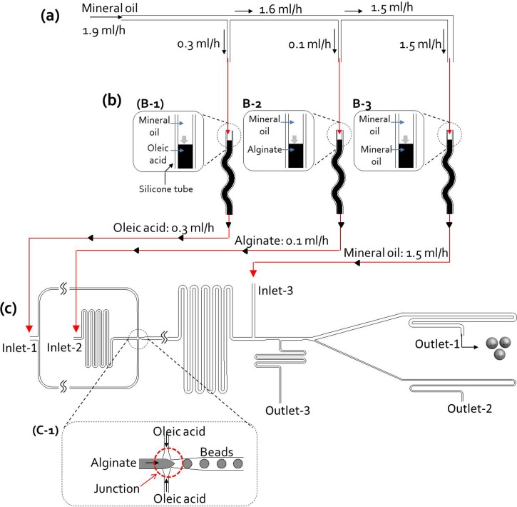
The operating principle of the microfluidic manifold platform. (a) Manifold chip for control of flow rates: The mineral oil contained in the syringe (10 ml) is injected into the manifold chip by a single syringe pump, and then distributed in the chip with the desired flow rates (outlet-1 for oleic acid: 0.3 ml/h, outlet-2 for alginate: 0.1 ml/h, and outlet-3 for mineral oil: 1.5 ml/h). (b) Silicone tubes containing working solutions ((b)-1: calcified oleic acid as continuous fluid, (b)-2: cell suspension in alginate solution, and (b)-3: mineral oil to remove oleic acid): Three solutions were first filled in each silicone tube, and then three solutions in silicone tubes are entered into bead generation chip by the distributed mineral oils (outlet-1, 2, and 3) in the manifold chip. (c) Two-phase bead generation: Calcified oleic acid, cell suspension in alginate solution was injected from inlet 1 and 2, mineral oil was injected from inlet 3 to substitute for the oleic acid. After the alginate droplets were generated by the shear flow of oleic acid at the bottleneck of the junction, they were polymerized into alginate beads by the infiltrated calcium in oleic acid while traveling in the 32-mm-long straight channel. At the end of the polymerization channel, mineral oil from inlet 3 replaces the oleic acid
Image analysis
The formation of droplets and encapsulation of cells were observed using a FASTCAM-Ultima 512 Imager high-speed CCD video camera (Photron, Tokyo, Japan) installed on a IX2-SLP phase inverted microscope (Olympus, Tokyo, Japan), where the images were recorded at 2000 frames/s.
RESULTS AND DISCUSSION
Characterization of the microfluidic manifold system
The previously reported microencapsulation system (w/o manifold) comprised four syringe pumps to generate cell-encapsulating beads (see supplementary material in Ref. 28 for Fig. S1). To reduce the number of syringe pumps, a manifold-based microfluidic platform, driven by a single syringe pump was designed (Fig. 1(a)). It was fabricated using soft lithography and replica molding (materials and methods).
This platform consists of (1) a manifold chip to control flow rates (Fig. 1(b) and Fig. S2(a) in Ref. 28), (2) silicone tubes containing working solutions (yellow silicone tube, calcified oleic acid as a continuous fluid; green silicone tube, cell suspensions in alginate solution; and white silicone tube, mineral oil to remove oleic acid) (Fig. 1(c)), and (3) a modified two-phase bead generation chip (Fig. 1(d) and Fig. S3 in Ref. 28). These parts were integrated by silicone tubes on the chip holder (Fig. 1(e)): an inlet of the manifold chip to adjust flow rates was connected to a silicone tube linked to the syringe pump, containing 10 ml of mineral oil; three outlets of the manifold chip were connected to silicone tubes containing three working fluids (calcified oleic acid as a continuous fluid, alginate solution containing cells, and mineral oil to remove oleic acid), and the other ends of the silicone tubes containing the three solutions were linked to three inlets (inlet-1 for calcified oleic acid; inlet-2 for alginate solution; and inlet-3 for mineral oil) of the two-phase bead generation chip.
The operating principle of the microfluidic manifold system
Figure 2 shows a diagram of the operating principle of the microfluidic manifold system. The mineral oil in the microsyringe was injected at a flow rate of 1.9 ml/h into the manifold chip from a single syringe pump and then divided into three channels at the desired volumetric flow rates in the manifold chip (Fig. 2(a)). The volumetric flow rates (outlet-1 for oleic acid, 0.3 ml/h; outlet-2 for alginate, 0.1 ml/h; and outlet-3 for mineral oil, 1.5 ml/h) in the microchannel network were controlled by adjusting the hydrodynamic resistances of the microchannels in the manifold chip (see Ref. 28 for Fig. S2(b)). A microchannel network can be designed by analogy with a simple electric circuit analysis.23,24 The flow rate at k connecting the microchannel, flow rate Qa,k, is described by Eq. (1). We fixed its fluid resistance as to simplify the electric circuit design and regulated the downstream channel resistance, to control the flow rate with Eq. (2). Because the flow rate through each resistance is known from Eq. (1), the necessary resistance was acquired from Kirchhoff's voltage law for a given ,
| (1) |
| (2) |
The electrical resistance was verified through the above equations using an electrical circuit simulation, and then converted to the dimensions of microchannel networks. The length and width of the connecting channel were calculated using the Hagen–Poiseuille equation.21,22 Hydrodynamic simulation (CFD RC, ESI-CFD, AL, USA) was also performed (see Ref. 28 for Fig. S2(c)) to confirm volumetric flow rates in the designed manifold chip microchannel network. The injected fluid (flow rate 1.9 ml/h) was distributed at regulated flow rates (outlet-1, 0.3 ml/h; outlet-2, 0.1 ml/h; and outlet-3, 1.5 ml/h). Thus, we controlled the desired flow rates automatically via the manifold chip, without any handling of the syringe pump.
The three working solutions were first filled in place into each silicone tube, and these tubes were connected to the outlet ports of the manifold chip and to the inlet ports of the bead generation chip (Fig. 2(b)). The solutions in three silicone tubes were pushed out by the distributed mineral oils (oleic acid: Fig. 2(b)-1; alginate: Fig. 2(b)-2; and mineral oil: Fig. 2(b)-3). During the operation of the chip, the amount of two solutions (the calcified oleic acid as continuous fluid, cell suspensions in alginate solution except without mineral oil) was regulated by adjusting the length of the silicone tubes (inner diameter 1 mm), depending on the operation time. The mineral oil, however, was provided directly from the 10 ml microsyringe used as a fluid power source. Finally, the three solutions were input in to the two-phase bead generation chip (Fig. 2(c)). When the manifold-based microfluidic platform is in operation, calcified oleic acid arrives earlier at the junction (Fig. 2(c)-1) with the chip than alginate solution because the flow rate of calcified oleic acid (0.3 ml/h) was higher than that of the alginate solution (0.1 ml/h). If alginate solution were to arrive earlier than the calcified oleic acid, the surface of the junction would be wetted by the alginate solution first, which would render the surface rather hydrophilic and make it difficult to break up droplets of alginate solution.
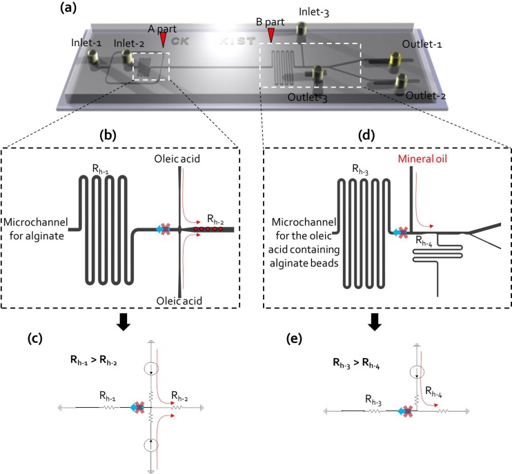
To successfully generate alginate beads, the injected calcified oleic acid must not flow into the alginate solution microchannel (Fig. 3(a): A part and Fig. 3(b)). This was ensured by hydrodynamic resistance control (Rh-1 > Rh-2) (Fig. 3(c)). This principle was also applied to the rapid oil exchange section, which transitioned the toxic oleic acid to a harmless mineral oil to maintain viability of cells in the alginate beads.16 The hydrodynamic resistances of the fluid exchange section (Fig. 3(a): B part) were also designed to prevent backward flow toward the microchannel of the oleic acid containing alginate beads (Fig. 3(d)). This was also ensured by controlling hydrodynamic resistance (Rh-3 > Rh-4) (Fig. 3(e)). There was therefore no need to manually adjust the flow rate in the syringe pump for successful bead generation. We confirmed that the oleic acid was completely removed by squeezing the flow of the mineral oil in the modified bead generation chip by hydrodynamic simulation (see Ref. 28 for Fig. S4(a)). When mineral oil at 1.5 ml/h was injected into inlet 3, the simulation analysis showed that oleic acid was squeezed by mineral oil and completely washed out into outlet 3 (see Ref. 28 for Fig. S4(b)).
FIG. 3.
(a) Schematic view of a two-phase bead generation chip; A part is a bead generation part and B part is a flow exchange part to remove the oleic acid. (b) The injected calcified oleic acid was not allowed to flow into the alginate solution channel (Fig. S3:28 A part). (c) It is guaranteed by the hydrodynamic resistance control (Rh-1 > Rh-2), electric circuit of microchannel networks of A part (bead generation part). (d) The hydrodynamic resistances of B part (flow exchange part) channels were also designed to obtain the desired fluid flowing. (e) Electric circuit of microchannel networks of B part (flow exchange part) (Rh-3 > Rh-4).
Chip operation
The mineral oil was divided into three channels in the manifold chip, and then entered into inlet 1 (calcified oleic acid), inlet 2 (alginate solution), and inlet 3 (mineral oil) of the bead generation chip. Alginate solution arrived later than the other two solutions because of its relatively low flow rate. Air droplets were first generated at the bottleneck of the junction by sheath flow of oleic acid (Fig. 4(a)-1, 4(a)-2, and Multimedia view) and the oleic acid containing air droplets was then squeezed by mineral oil (Fig. 4(a)-3, 4(a)-4, and Multimedia view). After arrival of the alginate solution, calcified oleic acid and alginate met at the bottleneck of the junction and alginate droplets were formed periodically by the shear flow of oleic acid (Fig. 4(b)-1 and Multimedia view). The generated alginate droplets were gelled by infused calcium from the oleic acid and flowed along the microchannel at regular intervals (Fig. 4(b)-2 and Multimedia view). The oleic acid was also completely removed by the squeezing flow of mineral oil (Fig. 4(b)-3 and Multimedia view). The gelled alginate beads in oleic acid crossed over the boundary between the two oils via hydrodynamic filtration16,23 and the beads were collected at outlet 1 by adjusting the hydrodynamic resistance of the two outlets (Fig. 4(b)-4 and Multimedia view).
FIG. 4.
Bead generation in the two-phase beads generation chip: First, air droplets were generated at the bottleneck of the junction by sheath flow of oleic acid ((a)-1 and (a)-2) and oleic acid containing air droplets were squeezed by mineral oil ((a)-3 and (a)-4). After arrival of alginate solution, they were met at the bottleneck of the junction, and then the alginate droplets were made periodically by the shear flow of oleic acid ((b)-1). The generated alginate droplets were gelified by infused calcium in oleic acid and flowed along the microchannel with a uniform gap maintaining ((b)-2). The oleic acid was completely removed by the squeezing flow of mineral oil ((b)-3). (Multimedia view) [URL: http://dx.doi.org/10.1063/1.4902943.1]
Generation of highly mono-disperse alginate beads
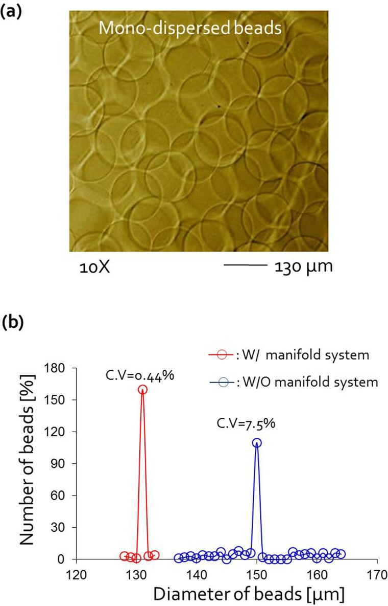
We assessed the mono-dispersity of the beads collected from the manifold-based microfluidic platform by comparing it with that of beads produced by the previous multi-syringe system (see Ref. 28 for Fig. S1 (Ref. 16)). The size distribution of beads produced in the manifold device was extremely sharp and its variation (CV = 0.44%) was smaller than that of the multi-syringe system (CV = 7.5%) (Figs. 5(a) and 5(b)) by more than 17 times. When several syringe pumps were used, pressure imbalances often occurred within the microfluidic channels, caused by external disturbances such as flow fluctuations generated from backlash of the syringe pumps, which could lead to the generation of polydisperse beads. In contrast, when the manifold with a single syringe pump was used, fluid flows were stabilized and no pressure disturbances occurred, because all modulated pressures were synchronized by the single pressure source.
FIG. 5.
(a) Photograph of the collected beads. The scale bar is 130 μm. (b) Diameter distribution of alginate beads in both the microfluidic manifold platform (W/manifold system) and the previous encapsulation system (W/O manifold component) using 4 syringe pump; the size-distribution of bead was extremely sharp in new device (CV = 0.44%) compared with previous device without manifold (CV = 7.5%).
Cell viability in the alginate beads
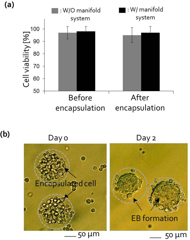
We also tested cell viability in the alginate beads with P 19 EC cells to verify whether the oil exchange system worked efficiently (Fig. 6(a)). Before encapsulating the cells in alginate beads, P 19 EC cells were first mixed in 1.8% alginate solution and meanwhile no serious degradation in cell viability was observed.25 After encapsulation, trypan blue staining was used to identify living and dead cells and cell viability assays were repeated three times. In both devices, cell viability in the alginate beads exceeded 95% after encapsulation because oleic acid was completely removed by the mineral oil. In addition, we evaluated the efficiency of spherical EBs formation with P19 EC cells for tissue engineering and cell therapy applications. Three-dimensional embryonic stem cell culture recapitulates the in vivo environment in the developmental stage and EC cell culture in alginate beads is a good model for studying the differentiation of stem cells. After encapsulation using the manifold-based microfluidic platform, P19 EC cells were cultured for 2 days in alginate beads. The cells in the alginate beads proliferated and aggregated into bumpy or round shapes in 2 days (Fig. 6(b)). This approach is advantageous for supplying massive embryonic bodies for the study of stem cell differentiation.
FIG. 6.
(a) The viability of IMR 90 cells after cell encapsulation was >95% of pre-encapsulation cell viability in both systems. (b) After encapsulation by the manifold system, P 19 EC cells were cultured for 2 days in alginate beads. The cells in the alginate beads proliferated and aggregated into bumpy or round shapes in 2 days. The scale bar is 50 μm.
CONCLUSIONS
Generation of mono-disperse alginate beads was achieved by a manifold-based microfluidic platform, which was driven by a single syringe pump. Although two-phase microencapsulation systems are efficient for making uniform-sized alginate beads encapsulating living cells, it is cumbersome for users in biological laboratories to use such microfluidic systems, because several syringe pumps must be carefully manipulated to setup initial flows of the working fluids in the microfluidic channels.
This paper proposes a microfluidic manifold system for encapsulating cells in alginate beads that can readily achieve the generation of mono-disperse spherical beads, as well as a high level of cell viability. Thus, a microfluidic chip can provide a reliable and cheap apparatus for microencapsulation of cells in alginate beads for cell therapy. However, there remain some technical issues that are yet to be solved. It is difficult to adjust the size of the alginate beads because the system was designed to inject fixed volumetric flow rates into the manifold and two-phase bead generation chip. Hence, several manifold chips should be prepared to obtain different sizes of beads or else valves with variable flow resistance must be installed.
Nevertheless, we believe this manifold concept is an important step towards efficient generation of alginate beads as well as the development of other two-phase flow systems for droplet generation. The proposed microfluidic manifold system will contribute to enhancing mono-dispersity when generating hydrogel beads via multi-phase microfluidic systems.
ACKNOWLEDGMENTS
This research was supported by a KIST grant, the Happy Technology Program, the Bio & Medical Technology Development Program, and the Pioneer Research Program for Converging Technology through the National Research Foundation (NRF) of Korea, funded by the Ministry of Education, Science and Technology (Nos. 2010-0020786, 2009-0091918, and 2010-0019347). This work was also supported by the 2014 Kyungil University Research Grant. Juyoung Park was also supported by Basic Science Research Program through the National Research Foundation of Korea (NRF) funded by the Ministry of Education (2012R1A6A3A04039347).
References
- 1.Dang S. M., Gerecht-Nir S., Chen J., Itskovitz-Eldor J., and Zandstra P. W., Stem Cells 22(3), 275 (2004). 10.1634/stemcells.22-3-275 [DOI] [PubMed] [Google Scholar]
- 2.Magyar J. P., Nemir M., Ehler E., Suter N., Perriard J. C., and Eppenberger H. M., Ann. N Y Acad. Sci. 944, 135 (2001). 10.1111/j.1749-6632.2001.tb03828.x [DOI] [PubMed] [Google Scholar]
- 3.Lorenzo-Lamosa M. L., Remunan-Lopez C., Vila-Jato J. L., and Alonso M. J., J. Control. Release 52(1-2), 109 (1998). 10.1016/S0168-3659(97)00203-4 [DOI] [PubMed] [Google Scholar]
- 4.Orive G., Hernandez R. M., Gascon A. R., Calafiore R., Chang T. M., Vos P. De, Hortelano G., Hunkeler D., Lacik I., Shapiro A. M., and Pedraz J. L., Nat. Med. 9(1), 104 (2003). 10.1038/nm0103-104 [DOI] [PubMed] [Google Scholar]
- 5.Dove A., Nat. Biotechnol. 20(4), 339 (2002). 10.1038/nbt0402-339 [DOI] [PubMed] [Google Scholar]
- 6.Vériter S., Mergen J., Goebbels R. M., Aouassar N., Grégoire C., Jordan B., Levêque P., Gallez B., Gianello P., and Dufrane D., Tissue Eng. Part A 16, 1503 (2010). 10.1089/ten.tea.2009.0286 [DOI] [PubMed] [Google Scholar]
- 7.Hortelano G., Al-Hendy A., Ofosu F. A., and Chang P. L., Blood 87(12), 5095 (1996). [PubMed] [Google Scholar]
- 8.Xu W., Liu L., and Charles I. G., FASEB J. 16(2), 213 (2002). [DOI] [PubMed] [Google Scholar]
- 9.Prakash S. and Chang T. M., Nat. Med. 2(8), 883 (1996). 10.1038/nm0896-883 [DOI] [PubMed] [Google Scholar]
- 10.Zimmermann H., Wählisch F., Baier C., Westhoff M., Reuss R., Zimmermann D., Behringer M., Ehrhart F., Katsen-Globa A., Giese C., Marx U., Sukhorukov V. L., Vásquez J. A., Jakob P., Shirley S. G., and Zimmermann U., Biomaterials 28(7), 1327 (2007). 10.1016/j.biomaterials.2006.11.032 [DOI] [PubMed] [Google Scholar]
- 11.Edd J. F., Carlo D. Di, Humphry K. J., Köster S., Irimia D., Weitz D. A., and Toner M., Lab Chip 8(8), 1262 (2008). 10.1039/b805456h [DOI] [PMC free article] [PubMed] [Google Scholar]
- 12.Song H., Chen D. L., and Ismagilov R. F., Angew. Chem., Int. Ed. Engl. 45(44), 7336 (2006). 10.1002/anie.200601554 [DOI] [PMC free article] [PubMed] [Google Scholar]
- 13.Shestopalov I., Tice J. D., and Ismagilov R. F., Lab Chip 4(4), 316 (2004). 10.1039/b403378g [DOI] [PubMed] [Google Scholar]
- 14.Koch S., Schwinger C., Kressler J., Heinzen C., and Rainov N. G., J. Microencapsul. 20(3), 303 (2003). 10.1080/0265204021000058438 [DOI] [PubMed] [Google Scholar]
- 15.Tan W.-H. and Takeuchi S., Adv. Mater 19(18), 2696 (2007). 10.1002/adma.200700433 [DOI] [Google Scholar]
- 16.Kim C., Lee K. S., Kim Y. E., Lee K. J., Lee S. H., Kim T. S., and Kang J. Y., Lab Chip 9(9), 1294 (2009). 10.1039/b819044e [DOI] [PubMed] [Google Scholar]
- 17.Rossow T., Heyman J. A., Ehrlicher A. J., Langhoff A., Weitz D. A., Haag R., and Seiffert S., J. Am. Chem. Soc. 134(10), 4983 (2012). 10.1021/ja300460p [DOI] [PubMed] [Google Scholar]
- 18.Abate A. R., Mary P., van Steijn V., and Weitz D. A., Lab Chip 12(12), 1516 (2012). 10.1039/c2lc21263c [DOI] [PubMed] [Google Scholar]
- 19.Romanowsky M. B., Abate A. R., Rotem A., Holtze C., and Weitz D. A., Lab Chip 12(12), 802 (2012). 10.1039/c2lc21033a [DOI] [PubMed] [Google Scholar]
- 20.Choi C. H., Yi H., Hwang S., Weitz D. A., and Lee C. S., Lab Chip 11(11), 1477 (2011). 10.1039/c0lc00711k [DOI] [PubMed] [Google Scholar]
- 21.Lian M., Collier C. P., Doktycz M. J., and Retterer S. T., Biomicrofluidics 6(4), 044108 (2012). 10.1063/1.4765337 [DOI] [PMC free article] [PubMed] [Google Scholar]
- 22.Workman V. L., Dunnett S. B., Kille P., and Palmer D. D., Biomicrofluidics 1(1), 014105 (2007). 10.1063/1.2431860 [DOI] [PMC free article] [PubMed] [Google Scholar]
- 23.Yamada M. and Seki M., Lab Chip 5(5), 1233 (2005) 10.1039/b509386d. [DOI] [PubMed] [Google Scholar]
- 24.Kim C., Lee K. S., Kim J. H., Shin K. S., Lee K. J., Kim T. S., and Kang J. Y., Lab Chip 8(8), 473 (2008). 10.1039/b714536e [DOI] [PubMed] [Google Scholar]
- 25.Kim C., Chung S., Kim Y. E., Lee K. S., Lee S. H., Oh K. W., and Kang J. Y., Lab Chip 11(2), 246–252 (2011). 10.1039/c0lc00036a [DOI] [PubMed] [Google Scholar]
- 26.Konno T., Akita K., Kurita K., and Ito Y., J. Biosci. Bioeng. 100(1), 88–93 (2005). 10.1263/jbb.100.88 [DOI] [PubMed] [Google Scholar]
- 27.Dang S. M., Kyba M., Perlingerio R., Daley G. O., and Zandstra P. W., Biotechnol. Bioeng. 78(4), 442–453 (2002). 10.1002/bit.10220 [DOI] [PubMed] [Google Scholar]
- 28.See supplementary material at http://dx.doi.org/10.1063/1.4902943E-BIOMGB-8-019406 for Figs. S1, S2, S3, and S4.
Associated Data
This section collects any data citations, data availability statements, or supplementary materials included in this article.
Data Citations
- See supplementary material at http://dx.doi.org/10.1063/1.4902943E-BIOMGB-8-019406 for Figs. S1, S2, S3, and S4.


