

Abstract
Currently deployed petascale supercomputers typically use toroidal network topologies in three or more dimensions. While these networks perform well for topology-agnostic codes on a few thousand nodes, leadership machines with 20,000 nodes require topology awareness to avoid network contention for communication-intensive codes. Topology adaptation is complicated by irregular node allocation shapes and holes due to dedicated input/output nodes or hardware failure. In the context of the popular molecular dynamics program NAMD, we present methods for mapping a periodic 3-D grid of fixed-size spatial decomposition domains to 3-D Cray Gemini and 5-D IBM Blue Gene/Q toroidal networks to enable hundred-million atom full machine simulations, and to similarly partition node allocations into compact domains for smaller simulations using multiple-copy algorithms. Additional enabling techniques are discussed and performance is reported for NCSA Blue Waters, ORNL Titan, ANL Mira, TACC Stampede, and NERSC Edison.
I. Introduction
Petascale computing is a transformative technology for biomolecular science, allowing for the first time the simulation at atomic resolution of structures on the scale of viruses and cellular organelles. These simulations are today a necessary partner to experimentation, not only interpreting data and suggesting new experiments, but functioning as a computational microscope to reveal details too small or too fast for any other instrument. With petascale biomolecular simulation today, modern science is taking critical steps towards understanding how life arises from the physical and chemical properties of finely constructed, but separately inanimate components.
To illustrate the significance of this capability, we consider two example simulations shown in Figure 1. On the left we have the first-ever atomic-level structure of a native, mature, HIV capsid, produced via the combination of cryo-electron microscopy and a 64 million-atom simulation using our program NAMD [1] on the Blue Waters Cray XE6 at NCSA. Although composed of a single repeating protein unit, arranged in pentamers and hexamers as in a fullerene, the capsid is non-symmetric and as such no single part can be simulated to represent the whole. The publication of the HIV capsid structure on the cover of Nature in May of 2013 [2] is only the beginning, and petascale simulations are now being used to explore the interactions of the full capsid with drugs and with host cell factors critical to the infective cycle.
Fig. 1.
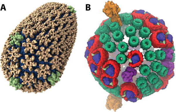
HIV capsid (A) and photosynthetic chromatophore (B).
On the right of Figure 1 is shown a 100 million-atom model of the photosynthetic chromatophore, a spherical organelle in photosynthetic bacteria that absorbs sunlight and generates chemical energy stored as ATP to sustain the cell. A 20 million-atom simulation of a smaller photosynthetic membrane has been performed already [3]. Simulating the entire spherical organelle will allow the study of how the 200 proteins of the chromatophore interlock to carry out some 30 processes, potentially guiding the development of bio-hybrid devices for efficient solar energy generation.
In pushing NAMD and its underlying runtime system, Charm++, towards petascale simulations of 100 million atoms on machines with hundreds of thousands of cores, many of the necessary modifications and extensions have been well anticipated. Having done previous work on topology adaptation for the Blue Gene series of machines, and anticipating the much-improved Cray Gemini network, optimization for torus networks should have been well understood. Unfortunately, our existing techniques were not suitable for the production environment we faced on Blue Waters and Titan, as while the machines were now large enough to face significant topology effects, the nodes allocated to particular jobs were often not compact blocks, and were always punctuated by I/O nodes.
This paper presents a collection of related techniques implemented in NAMD for robustly and elegantly mapping several object-based parallel decompositions to the irregular torus topologies found on Cray XE6/XK7 platforms. These techniques rely on the cross-platform Charm++ topology information API and recursive bisection to produce efficient mappings even on non-toroidal networks. The specific decompositions addressed are machine partitioning for multiple copy algorithms, mapping of NAMD’s fixed-size spatial decomposition domains onto the machine torus, and mapping of the particle-mesh Ewald (PME) full electrostatics 3-D Fast Fourier Transform (FFT) onto the spatial decomposition. Additional optimizations presented are the coarsening of the PME grid via 8th-order interpolation to reduce long-range communication, the offloading of PME interpolation to the GPUs on Cray XK7, and the removal of implicit synchronization from the pressure control algorithm.
We present performance data for benchmarks of 21M and 224M atoms on up to 16,384 nodes of the NCSA Blue Waters Cray XE6, the ORNL Titan Cray XK7, and the ANL Mira Blue Gene/Q, as well as 4096 nodes of the NERSC Edison Cray XC30 and 2048 nodes of the TACC Stampede InfiniBand cluster. The performance impact of individual optimizations is demonstrated on Titan XK7.
II. Background
Both NAMD [1] and Charm++ [4] have been studied extensively for performance optimizations and scalability. A significant amount of research has also been performed on topology aware mapping to improve application performance. In this section, we briefly summarize these key topics and state how the presented work differs from past work.
A. Charm++
Charm++ [5], [6] is an overdecomposition-based message-driven parallel programming model. It encourages decomposition of the application domain into logical entities that resemble the data and work units of the application. The program is defined in terms of these entities, encapsulated as C++ objects, called chares. Under the hood, a powerful runtime system (RTS) maps and schedules execution of the chares on processors. The order of execution is determined by the presence of data (messages for chares) and priorities assigned to them by the programmer. Decomposition into chares and empowering of the RTS enables adaptivity to enhance both the programming productivity and performance. In particular, the chares can be migrated from one processor to another by the RTS, which allows load balancing.
On most machines, Charm++ is implemented on top of the low-level communication layer, provided by the system, for best performance (called native builds). PAMI [7], [8], uGNI [9], [10], [11], and IB-Verbs [12] are used on IBM Blue Gene/Q, Cray XE6/XK7/XC30, and InfiniBand clusters respectively for native builds. Charm++ can also be built on top of MPI on any system. On fat nodes, Charm++ is typically built in SMP mode, in which a process is composed of a dedicated communication thread for off-node communication and the remaining threads for computation. Many Charm++ applications, including NAMD [1], OpenAtom [13], and EpiSimdemics [14], have been shown to scale to hundreds of thousands of cores using the native builds and the SMP mode.
While the default practice is to delegate all decision making to the RTS, the programmer can also help the RTS in making optimal decisions. Given that many programmers are familiar with the computation and communication characteristics of their applications, such guidance can improve performance significantly. Mapping of chares onto the processor allocation is one of the important decisions in which programmers can guide the RTS; user-defined novel mapping strategies for biomolecular applications is a key contribution of this paper.
B. NAMD
The form and function of all living things originate at the molecular level. Extensive experimental studies, based on X-ray diffraction and cryo-electron microscopy, are performed to study biomolecular structures and locate positions of the protein atoms. While these experimentally determined structures are of great utility, they represent only static and average structures. Currently, it is not possible to observe the detailed atomic motions that lead to function. Physics-based simulations are of great utility here in enabling the study of biomolecular function in full atomic detail.
NAMD [1] is heavily used for such simulations of the molecular dynamics of biological systems. Its primary focus is on all-atoms simulation methods using empirical force fields with a femtosecond time step resolution. Given that biological systems of interest are of fixed size, the stress for NAMD is on strong scaling, which requires extremely fine-grained parallelization, in order to simulate systems of interest in reasonable time.
Parallel Decomposition
NAMD is implemented on top of Charm++, and thus provides an object-based decomposition for parallel execution. Atomic data is decomposed into equally-sized spatial domains, called patches, whose extent is determined by the short-range interaction cutoff distance. The work required for calculation of short-range interactions is decomposed into computes. Each compute is responsible for computing forces between a pair of patches. The long range interaction is computed using the 3-D Fast Fourier Transform (FFT) based particle-mesh Ewald method (PME). The 3-D FFT is decomposed into pencils along each dimension (X, Y, Z). The short-range and long-range interactions are computed simultaneously as they are scheduled by Charm++’s RTS with priority being given to long-range interactions. Note that the object-based decomposition of NAMD is independent of the process count and allows for fine-grained parallelization necessary for scalability. At scale, the performance of NAMD is significantly impacted by the mapping of the patches, computes, and pencils on the processors (Section VII).
GPU Acceleration
The short-range interaction computation is the most compute intensive component in NAMD. Therefore, NAMD offloads this computation to GPUs on systems with GPUs [15]. Every compute assigned to a GPU is mapped to a few GPU multiprocessor work units (typically one or two). After the data is copied to the GPU by the CPU, two sets of work units are scheduled. The first set calculates forces for remote atoms, which requires off-node communication; the second set calculates forces for local atoms only. This allows some overlap of communication and computation [16]. In the current GPU design of NAMD, each GPU is managed by a single shared context on a node (in SMP mode). This arrangement greatly increases the amount of work available to the GPU to execute in parallel, in comparison to the old mode in which each thread managed its own context with the GPU. This also eliminates redundant copying of atom coordinates to the GPU. A similar offload strategy is used for the Intel Xeon Phi coprocessor.
Petascale Adaptations
Since the advent of petascale systems, NAMD has been heavily optimized to provide scalability on leadership class supercomputers. Mei et al. showed the utility of the node-awareness techniques deployed in NAMD to scale it to the full Jaguar PF Cray XT5 (224, 076 cores) [17]. Building on that work, Sun et al. explored several techniques for improving fine-grained communication on uGNI [11]. For the 100-million-atom STMV system, they improved the time per step from 26 ms/step on Jaguar XT5 to 13 ms/step using 298, 992 cores of Jaguar XK6. Kumar et al.’s work on optimizing NAMD on IBM’s Blue Gene/Q resulted in time per step of 683 microseconds with PME every 4 steps for the 92,000-atom ApoA1 benchmark.
C. Multiple-copy Algorithms and Charm++ Partitions
Multiple-copy algorithms (MCA) refer to the methodology in which a set of replicated copies of a system are studied simultaneously. They provide a powerful method to characterize complex molecular processes by providing for enhanced sampling, computation of free energies, and refinement of transition pathways. Recently, a robust and generalized implementation of MCAs has been added to NAMD based on the partition framework in Charm++ [18].
Charm++’s generalized partition framework is designed to enable execution of multiple Charm++ instances within a single job execution. When the user passes a runtime argument, +partitions n, the Charm++ RTS divides the allocated set of processes into n disjoint sets. Each of these sets are independent Charm++ instances (similar to MPI subcommunicators) in which a traditional Charm++ instance can be executed. Additionally, there is API support for these instances to communicate with other instances executing in the same job, and for mapping the partitions using topology aware algorithms.
NAMD leverages the partition framework to launch several NAMD instances in a replicated execution. In order to communicate between the NAMD instances, a new API has been added to its Tcl scripting interface, which in turn uses the API exposed by Charm++ for inter-partition communication. The Tcl based API serves as a powerful tool because it enables generalized MCAs without any modification to the NAMD source code. NAMD’s MCA implementation has been demonstrated to be massively scalable, in part due to the scalable partition framework of Charm++ [18].
D. Topology Aware Mapping
In order to scale to hundreds of thousands of cores, exploiting topology awareness is critical for scalable applications such as NAMD. A majority of current top supercomputers deploy torus-based topologies. IBM Blue Gene/Q is built upon a 5-dimensional torus with bidirectional link bandwidth of 2 GB/s [19]. Cray’s XE6/XK7 systems are based on Gemini Interconnect, which is a 3-dimensional torus with variable link bandwidths [20]. As a result, mapping on torus topologies has been an active research topic for the HPC community in general, and for NAMD in particular.
Yu et al. presented embedding techniques for three-dimensional grids and tori, which were used in a BG/L MPI library [21]. Agrawal et al. described a process for mapping that heuristically minimizes the total number of hop-bytes communicated [22]. Bhatele proposed many schemes and demonstrated the utility of mapping for structured and unstructured communication patterns on torus interconnects [23]. The work presented in the current paper differs from all of the above work in the topology it targets. Finding a good mapping in the presence of holes in an irregular grid is significantly harder in comparison to finding a similar mapping on a compact regular grid. For irregular topologies, Hoefler et al. presented an efficient and fast heuristic based on graph similarity [24]. However, the generality in their approach ignores the fact that the target topology is part of a torus and thus is not optimal for the given purpose.
Charm++ provides a generic topology API, called TopoManager, that supports user queries to discover the topology of torus networks. It also provides an API that helps in making Charm++ applications node-aware. NAMD extensively utilizes these features to map patches and computes in an efficient manner on machines that provide compact allocations, such as IBM Blue Gene/P and IBM Blue Gene/Q [25], [26]. However, efficient mapping on irregular grids with holes in the allocated set had not been done in NAMD before, and is the topic of this paper.
III. Mapping of Charm++ Partitions
Multiple-copy algorithms employ ensembles of similar simulations (called replicas) that are loosely coupled, with infrequent information exchanges separated by independent runs of perhaps a hundred timesteps. The information exchanged may be an aggregate quantity, such as the total energy of the simulation or the potential energy of an applied bias. Based on the exchanged value and possibly a random number, some state is generally exchanged between pairs of neighboring replicas. This state is often a control parameter such as a target temperature or a bias parameter, but may be as large as the positions and velocities of all atoms in the simulation. Still, the data transferred between partitions is almost always significantly less than the data transferred among nodes within a partition during a typical timestep. Therefore, data exchange between partitions can normally be neglected when optimizing the performance of a multiple-copy simulation.
Due to the periodic coupling between replica simulations, the performance of the collective simulation will be limited to the performance of the slowest replica during each successive independent run; perfect efficiency is achieved only if all partitions perform at the same rate. The low performance of the slowest replica may be due to static effects, resulting in consistently lower performance for a given partition across timesteps and runs. It may also be low due to dynamic performance variability, resulting in different partitions limiting aggregate performance on different runs. Dynamic performance variability may be due to properties of the code, such as data-dependent algorithms responding to divergent replica simulations, or due to properties of the machine, such as system or network noise. The later, machine-driven performance divergence, can be minimized by selecting the division of the nodes assigned to a job such that the partitions on which the replica simulations run are as compact and uniform as possible.
A naive partitioning algorithm that is employed in Charm++ by default is to simply assign to each partition a contiguous set of ranks in the overall parallel job. Thus the first partition, of size p, is assigned the first p ranks, etc. Naive partitioning is at the mercy of the job launch mechanism, and is therefore subject to various pathological conditions. The worst case would be for the queueing system to use a round-robin mapping of ranks to hosts when multiple ranks are assigned to each host, resulting in each partition being spread across unnecessarily many hosts and each host being shared by multiple partitions. Assuming, however, that ranks are mapped to hosts in blocks, then naive partitioning is as good as one can achieve on typical switch-based clusters for which the structure of the underlying switch hierarchy is not known. If the hosts in such a cluster are in fact mapped blockwise to leaf switches, and this ordering is preserved by the job scheduler and launcher, then naive partitioning will tend to limit partitions to a minimal number of leaf switches. Similarly, any locality-preserving properties of the job scheduler and launcher of a torus-based machine will be preserved by naive mapping.
In order to avoid the uncertainty of naive partitioning, we have implemented in Charm++ a topology-adapted partitioning algorithm for toroidal network topologies, based on recursive bisection. Because the method is intended for loosely coupled multiple-copy algorithms, variation in the degree of coupling between particular pairs of replicas is neglected, allowing a simpler algorithm than that described in Section IV for the mapping of NAMD’s spatial domains. The only goal of the partitioning algorithm is compactness of partitions, defined roughly as minimizing the maximum distance between any two ranks in the same partition.
The first phase of the algorithm is to convert the raw torus coordinates provided by the Charm++ TopoManager API to an optimized mesh topology. We note that Cray XE/XK machines can be configured as torus or mesh topologies. While an API for determining the torus/mesh dimensions exists, the API does not distinguish between torus and mesh configurations. We are therefore forced to assume a torus configuration in all cases, based on the logic that all large machines use the torus configuration, while any topology-based optimization on smaller mesh-based machines will be of little effect anyway.
Having assumed a torus topology, the optimized mesh topology is determined as follows. First, to guard against fallback implementations of the TopoManager API, the torus coordinates of each rank are mapped to the coordinates of the first rank in its physical node, employing an independent Charm++ API that detects when ranks are running on the same host. This mapping to physical nodes also guards against round-robin rank assignment. Second, all nodes are iterated over to determine for each torus dimension those positions that are occupied by one or more ranks. The set of occupied positions in each dimension is then scanned to find the largest gap, taking the torus periodicity into account; the torus coordinates along each dimension are shifted such that the first position past the end of the gap becomes zero. For example, a torus dimension of length 12 with the occupied positions 3, 5, 6, 9 would be found to have a largest gap of length 5 spanning positions 10, 11, 0, 1, 2. It would then be shifted by −3 to optimized positions 0, 2, 3, 6 with an optimized mesh length of 7. Similarly, occupied positions 2, 3, 10 have a largest gap of length 6 spanning 4–9, and would be shifted by −10 (modulo 12) to optimized positions 0, 4, 5. Finally, the optimized mesh dimensions are re-ordered from longest to shortest occupied span.
The above optimized mesh topology is implemented as a TopoManagerWrapper class with an additional functionality of sorting a list of ranks by their optimized mesh coordinates hierarchically along an ordered list of dimensions, with the first dimension varying most slowly and the last dimension varying most rapidly. The sorting is further done in the manner of a simple “snake scanning” space-filling curve, reversing directions at the end of each dimension rather than jumping discontinuously to the start of the next line (see Fig. 2). This sort functionality allows the recursive bisection partitioning algorithm to be written simply as follows: Given a range of partitions [0, N) and a set of P ranks such that N evenly divides P (assuming equal-sized partitions), (1) find the minimal bounding box of the optimized mesh coordinates for all ranks in the set, (2) sort the ranks hierarchically by dimension from the longest to the shortest bounding box dimension (longest varying most slowly), (3) bisect the partition range and (proportionally for odd N) the set of ranks, and (4) recurse on the lower and upper halves of the partition range and rank set.
Fig. 2.

Two stages of recursive bisection topology-adapted partition mapping. The underlying grid represents nodes in the torus, with gaps for nodes that are down, in use by other jobs, dedicated to I/O, or otherwise unavailable. The dark lines represent the sorted node traversal order for bisection, aligned on the left with the major axis of the full allocated mesh and on the right with the major axes of the bisected sub-meshes. Grid element color represents recursive bisection domains after each stage.
The above partitioning algorithm, illustrated in Fig. 2, extends to any dimension of torus, makes no assumptions about the shape of the network, handles irregular allocations and gaps implicitly, and reduces to the naive partitioning algorithm in non-toroidal topologies.
IV. Mapping of NAMD Spatial Domains
We now extend the above topology-adapted partitioning algorithm to support mapping of the fixed size 3-D grid of spatial domains (termed patches). The primary goals of this mapping is to achieve both load balance among the available ranks and compactness of the patch set assigned to each physical node, thus minimizing the amount of data sent across the network. Mapping the patch grid to the torus network of the machine is of secondary importance. This assignment is complicated by the facts that not every PE (a Charm++ processing element, generally a thread bound to a single core) may have a patch assigned to it, and that patches have different estimated loads based on their initial atom counts.
The set of PEs to which patches will be assigned is determined by excluding PEs dedicated to special tasks, such as global control functions on PE 0. If the remaining PEs exceed the total number of patches, then a number of PEs equal to the number of patches is selected based on bit-reversal ordering at the physical node, process, and thread-rank level to distribute the patches evenly across the machine. Thus the set of available PEs is never larger than the set of patches. The load of each patch is estimated as a + natoms, where a represents the number of atoms equivalent to the per-patch overheads.
Recursive bisection of the patch mesh is analogous to the recursive bisection of the network optimized mesh topology above. The complications are that the set of PEs must be split on physical node boundaries, and that the set of patches must be split to proportionately balance load between the lower and upper sets of PEs, but still guaranteeing that there is at least one patch per PE in both the lower and upper sets of PEs.
The patch mapping algorithm begins by associating the longest dimension of the full patch grid with the longest dimension of the network optimized mesh topology, and similarly the second and third-longest dimensions of both. These associations are permanent, and when dividing the patch grid along any dimension, the set of available PEs will be divided along the corresponding dimension, if possible, before falling back to the next-longest dimension.
Having associated axes of the patch grid with those of the network torus, the assignment of patches to PEs proceeds as follows: Given a set of patches and a set of at most the same number of PEs, (1) find the minimal bounding boxes of both the patches and the PEs, (2) sort the patches hierarchically by dimension from longest to shortest, (3) sort the PEs hierarchically by dimensions corresponding to those by which the patches are sorted and then the remaining longest to shortest, (4) bisect the PEs on a physical node boundary, (5) bisect the patches proportionately by estimated load with at least one patch per PE, and (6) recurse on the lower and upper halves of the PE and patch sets.
If at step (4) all PEs are on the same physical node, then the PEs are sorted by rank within the node and the patches are sorted along the original user-specified basis vectors (typically x,y,z) since these correspond to the alignments of the PME 1-D (slab) and 2-D (pencil) decomposition domains and this sorting reduces the number of slabs or pencils with which each PE will interact.
V. Reducing PME Communication
The PME full electrostatics evaluation method requires two patterns of communication. The first pattern is the accumulation of gridded charges from each PE containing patches to the PEs that will perform the 3-D FFT, with the reverse communication path used to distribute gridded electrostatic potentials back to the patch PEs, which then interpolate forces from the electrostatic gradient. The second pattern is the 3-D FFT and inverse FFT, which requires a total of two transposes for a 1-D decomposition or four for 2-D. In general a 1-D decomposition is employed for smaller simulations and a 2-D decomposition is employed for larger simulations on larger node counts.
In optimizing the charge/potential grid communication pattern we exploit the fact that both the patch grid and the PME grid share the same origin in the simulation space and fill the periodic cell. Unfortunately, the dimensions of the 3-D patch grid and the 2-D PME pencil grid share no special relationship, and, as discussed above, the patch grid mapping is designed for 3-D compactness. Finally, we require the PME pencil mapping to perform well independently of what topology mapping is employed for the patch grid.
On larger node counts not all PEs will contain a PME pencil. This is due to decomposition overhead as pencils approach a single grid line and due to contention for the network interface on the host. There are three types of pencils: Z, Y, and X, with the 2-D grid of Z pencils distributed across the X-Y plane communicating with patches, and Y and X pencils only participating in the 3-D FFT transposes. Pencils of each type are distributed evenly across the processes and physical nodes of the job to better utilize available network bandwidth, preferring in particular for the Z pencils any PEs that do not contain patches.
Thus our goal is to efficiently map the Z pencil grid of size nx by ny to a pre-selected set of exactly nx × ny PEs. We begin by calculating for each PE the average spatial coordinate of the patches it contains or, if it has no patches, the average coordinate of the patches of PEs in its process or, failing that, the average coordinate of the patches of PEs on its physical node. Extending the search for patches to the physical node is common, as for smaller simulations NAMD is often run in single-threaded mode with one process per core.
Having associated x, y coordinates with each PE (the z coordinate is not used), we now employ recursive bisection to map the pencil grid to the PEs as follows: Given an nx by ny pencil grid and an equal number of PEs, (1) select the longer dimension of the pencil grid (preferring X if equal), (2) bisect the pencil grid on the selected dimension only (i.e, 5 × 5 becomes 2 × 5 and 3 × 5) (3) sort the PEs by the corresponding coordinate, (4) bisect the sorted PEs proportionately with the pencil grid (i.e, 25 above becomes 10 and 15), and (5) recurse on the lower and upper halves of the pencil and PE sets.
With the Z pencils thus aligned to the patch grid, the next issue is the mapping of the Y and X pencils so as to perform the 3-D FFT transposes most efficiently. Beyond distributing the pencils evenly across processes and physical nodes, as noted above, we have as yet no clear answer, as optimizing Z pencil to Y pencil communication (nx simultaneous transposes between Z and Y pencils with the same X coordinate) tends to pessimize Y pencil to X pencil transpose communication. This is not unexpected, given that the algorithm evaluates long-range electrostatics, an inherently global calculation. Our current compromise is to optimize the Y to X to Y pencil transposes by keeping X and Y pencils with the same Z coordinate on contiguous ranks on the assumption that rank proximity correlates with network connectivity.
Fortunately, FFT transpose communication for most NAMD simulations is effectively overlapped and hidden by short-range force evaluations. It is only for the largest simulations on the largest and fastest machines that PME communication becomes a severe drag on performance and scaling. It is also for very large simulations that the runtime of the FFT itself becomes significant, due to its N log N scaling and the parallel bottleneck of individual FFTs in each dimension. Therefore, it is desirable to reduce both the size of PME communication and the FFT runtime by coarsening the PME mesh from the standard 1Å to 2Å.
There are two methods for preserving accuracy while coarsening the PME mesh. The first method is to proportionally increase the cutoff distance of the PME direct sum, which is integrated into the NAMD short-range nonbonded force calculation, while accordingly modifying the Ewald factor. The cost of the direct sum is proportional to the cube of the cutoff distance, so doubling the cutoff distance for a 2Å grid would greatly increase an already major part of the calculation by up to a factor of 8. Although in NAMD’s multiple timestepping scheme this longer cutoff would only be required in theory for timesteps on which PME is performed, maintaining multiple cutoffs, pairlists, and short-range communication patterns would greatly complicate the code.
The second method is to increase the PME b-spline interpolation order from 4 to 8. 4th-order interpolation spreads each charge to a 4 × 4 × 4 area of the PME charge grid, while 8th-order interpolation spreads each charge to an 8 × 8 × 8 area. While this is a factor of 8 increase in interpolation work per atom, the total number of charge grid cells affected per patch is greatly reduced; also each patch PE sends less overall data to a larger number of pencils. A PME interpolation order of 8 has long been supported in NAMD, so the only additional development required was optimization of this little-used code path. Note that 8th-order interpolation with a 2Å mesh is only a performance benefit for petascale simulations, as smaller simulations on smaller machines do not achieve sufficient benefit from the reduced FFT and communication to compensate for the increased cost of interpolation.
For traditional CPU-based machines such as Blue Gene/Q and Cray XE6, even the increased cost of 8th-order PME interpolation is small compared to the short-range nonbonded calculation. For GPU-based machines such as Cray XK7, however, the short-range nonbonded calculation is greatly accelerated by the GPU and 8th-order PME interpolation becomes of comparable cost, but performance is still limited by GPU performance in many cases at this time. For very large simulations on large machines, however, the PME FFT transpose communication becomes a limit on performance and it is therefore desirable to move PME interpolation to the GPU, allowing PME communication to begin earlier and end later in the timestep.
The NAMD PME interpolation CUDA kernels target the NVIDIA Kepler architecture, using fast coalesced atomic operations to accumulate charges onto the grid. The initial implementation maintained a separate charge grid for each PE, but this was later aggregated into a single grid per GPU. This aggregation eliminated multiple messages being sent to the same pencil by PEs sharing the same GPU, and was a necessary optimization to realize a performance increase from offloading PME interpolation to the GPU. A performance improvement would also likely be observed on non-PME-offloaded runs or CPU-only machines from similarly aggregating PME data to a single grid per process or per physical node, particularly going forward due to the continuing increase in core and thread counts per node.
VI. Reducing Barostat Synchronization
The design of NAMD attempts to avoid global synchronization whenever possible so as to allow staggering and overlap of computation and communication between different PEs. This design is enabled by the message-driven programming style of Charm++, and is one of the unique features of NAMD among molecular dynamics programs. Explicit global barriers in NAMD are used only to simplify the code and to ensure correctness in non-performance-critical operations, such as separating startup phases or when returning control to the master Tcl interpreter. These explicit barriers rely on Charm++ quiescence detection to ensure that all messages in flight have been received and processed and have themselves generated no additional outgoing messages.
It is still possible in Charm++ message-driven programming to introduce implicit synchronization via serialization of the control flow of the program through an (otherwise nominally asynchronous) reduction and broadcast. An example of implicit synchronization would be a simulation temperature control mechanism (i.e., a thermostat) that requires a reduction of the total kinetic energy of the simulation, followed by a broadcast of a velocity rescaling factor that must be received to advance atomic positions so that force evaluation for the next timestep can begin. Such synchronizations cause spikes in network traffic and contention, and can generate cascading message floods as atomic coordinate messages from early broadcast recipients overtake and delay the broadcast itself.
NAMD avoids implicit synchronization in temperature control by employing the non-global method of weakly-coupled Langevin dynamics, in which the average temperature of each atom is controlled stochastically by the addition of small friction and random noise terms to the equations of motion. The total system temperature is used to monitor the simulation, but is not a control parameter and the simulation proceeds even if the kinetic energy reduction is delayed.
Unfortunately, the method of controlling pressure in the simulation cell (i.e., the barostat) is to adjust the cell volume by rescaling the cell periodic basis vectors and all atomic coordinates, which is necessarily a global operation requiring the globally reduced pressure as a control parameter, and hence introducing synchronization. As the PME contribution to the pressure is available only on timesteps for which PME is calculated it is not valid to calculate the pressure more often than PME, and hence with multiple timestepping the frequency of synchronization is reduced to that of PME full electrostatics evaluation (2–4 steps).
The barostat equation of motion used in NAMD is in essence (neglecting damping and noise terms) of the form V″ = (P − Ptarget)/W, where V is the cell volume, P and Ptarget are measured and target pressures, and W is the conceptual “mass” of a piston that compresses or expands the cell. The piston mass W is set large enough that the piston oscillation period is on the order of 100 timesteps, to allow the high level of noise in the instantaneous pressure to be averaged out over time. The barostat is discretized with timestep h as and (neglecting multiple timestepping for clarity). The broadcast of Vi+1 is necessary to begin force evaluation for step i + 1, but depends on the Pi pressure reduction, introducing the implicit synchronization.
For very large simulations for which this synchronization imposes a significant performance penalty, NAMD can introduce a single timestep (i.e., a full force evaluation cycle) of delay between the pressure reduction and the cell rescaling broadcast. This delay is possible because the cell strain rate V′ changes slowly. The lagged integrator is ; . Note that Vi+1 is now available before the Pi reduction is received, allowing the Pi−1 reduction and Vi+1 broadcast to overlap with the step i force evaluation, and thus eliminating the implicit synchronization.
The error induced by the modified barostat integrator may be made arbitrarily small by increasing the barostat mass and therefore period. The barostat period is very long already due to the high noise level in the instantaneous pressure that dwarfs barostat feedback, and noise/damping terms are used to ensure barostat thermal equilibrium and avoid sustained oscillation.
VII. Results
A. Benchmark Simulations
Developing biomolecular model inputs for petascale simulations is an extensive intellectual effort in itself, often involving experimental collaboration. As this is leading-edge work we do not have previously published models available, can not justify the resources to build and equilibrate throwaway benchmarks, and cannot ask our users to provide us their in-progress work which we would then need to secure. By using synthetic benchmarks for performance measurement we have a known stable simulation that is freely distributable, allowing others to replicate our work.
Two synthetic benchmarks were assembled by replicating a fully solvated 1.06M atom satellite tobacco mosiac virus (STMV) model with a cubic periodic cell of dimension 216.832Å. The 20stmv benchmark is a 5 × 2 × 2 grid containing 21M atoms, representing the smaller end of petascale simulations. The 210stmv benchmark is a 7 × 6 × 5 grid containing 224M atoms, representing the largest NAMD simulation contemplated to our knowledge. Both simulations employ a 2fs timestep, enabled by a rigid water model and constrained lengths for bonds involving hydrogen, and a 12Å cutoff. PME full electrostatics is evaluated every three steps and pressure control is enabled.
Titan Cray XK7 binaries were built with Charm++ platform gemini_gni-crayxe-persistent-smp and launched with aprun arguments “-r 1 -N 1 -d 15” and NAMD arguments “+ppn 14 +pemap 0–13 +commap 14”. Blue Waters Cray XE6 binaries were built with Charm++ platform gemini_gni-crayxe-persistent-smp and launched with aprun arguments “-r 1 -N 1 -d 31” and NAMD arguments “+ppn 30 +pemap 1–30 +commap 0”. Mira Blue Gene/Q binaries were built with Charm++ platform pami-bluegeneq-async-smp-xlc for single-copy runs and pamilrts-bluegeneq-async-smp-xlc for multiple-copy runs, and launched in mode c1 with environment BG SHAREDMEMSIZE=32MB and NAMD argument +ppn48. Edison Cray XC30 binaries were built with Charm++ platform gni-crayxc-smp and launched with aprun arguments “-j 2 -r 1 -N 1 -d 47” and NAMD arguments “+ppn 46 +pemap 0–22,24–46 +commap 23” except for the 21M atom benchmark on 4096 nodes, which was launched with aprun arguments “-r 1 -N 1 -d 23” and NAMD arguments “+ppn 22 +pemap 1–22 +commap 0”. Stampede InfiniBand cluster binaries were built with Charm++ platform net-linux-x86_64-ibverbs-smp-iccstatic and launched with one process per node with charmrun arguments “++ppn 15 ++mpiexec ++remote-shell /path/to/ibrun wrapper” (ibrun wrapper is a script that drops its first two arguments and passes the rest to /usr/local/bin/ibrun) and NAMD arguments “+commap 0 +pemap 1–15” (except “++ppn 14” and “+pemap 1–14” for 21M atoms with Xeon Phi on 2048 nodes), adding “+devices 0” for Xeon Phi runs to avoid automatically using all Phi coprocessors present on a node. Reported timings are the median of the last five NAMD “Benchmark time” outputs, which are generated at 120-step intervals after initial load balancing.
B. Network Metrics
In order to quantify how the various topology mappings affect the network communication, we have measured the network packets sent over each link for every physical node using the Blue Gene/Q Hardware Performance Monitoring API (BGPM), which provides various network event counters. In our experiments, we have collected the count of 32-byte chunks sent on a link for each of the 10 links connected to a node. The corresponding event is PEVT_NW_USER_PP_SENT.
Figure 3 shows the maximum and average communication over 10 links on each node of 1024 nodes using randomized and optimized topology mappings for the 21M atom benchmark. Optimized mapping significantly reduces the maximum chunks sent over each link as shown in Figs. 3(a) and 3(b). The maximum communication for each node using randomized topology ranges from 932, 291 32-byte chunks to 2,038, 856 32-byte chunks. In contrast, the range using an optimized topology is from 420, 075 chunks to 755, 867 chunks. The ratio is as high as 2.70. Meanwhile, the average chunks sent over all 10 links are also greatly reduced as shown in Figs. 3(c) and 3(d). The average count for 1024 nodes using randomized topology is 657, 748 chunks, while it is 340, 279 chunks using optimized topology. The ratio is as high as 1.93. These numbers shows that our topology mapping scheme decreases both the maximum number of chunks sent over any link and the average traffic sent over the network.
Fig. 3.

Maximum and average number of packets sent over each node’s ten 5-D torus network links by NAMD running the 21M atom benchmark on 1024 nodes of Mira IBM Blue Gene/Q using randomized and optimized topology. The nodes are represented in a 32 × 32 grid for presentation purposes only. The value of each element is the number of 32-byte chunks sent. Darker shades indicate more communication.
C. Performance Impact of Optimizations
Having demonstrated that our topology mapping method does reduce network traffic on Blue Gene/Q, we run the two benchmark systems across a range of node counts for three conditions: fully topology adapted, machine node ordering (topology adaptation disabled and taking the nodes in the machine native rank order), and topology randomized (topology adaptation disabled and node order randomized). The results, shown in Fig. 4, demonstrate no improvement. This is in fact a great triumph of the 5-D torus network, at least relative to the performance achieved by NAMD on the machine. The limited scaling from 4096 to 8192 nodes for the smaller benchmark is likely due to parallelization overheads, as 48 threads per node are used to keep the 16 cores, each with 4 hardware threads, busy. Even 4096 nodes represents 196,608-way parallelism for 21M atoms, barely 100 atoms per PE.
Fig. 4.
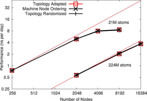
NAMD strong scaling on Mira IBM Blue Gene/Q for 21M and 224M atom benchmarks. Topology adaptation has little impact on performance.
We repeat this experiment on the GPU-accelerated Titan Cray XK7. While on Blue Gene/Q jobs run in isolated partitions of fixed power-of-two dimensions and therefore exhibit consistent and repeatable performance, on Cray XE6/XK7 nodes are assigned to the jobs by the scheduler based on availability. Hence, even jobs that run back-to-back may experience greatly differing topologies. In order to eliminate this source of variability, all comparisons between cases for the same benchmark system on the same node count are run within a single job and therefore on the exact same set of nodes.
As shown in Fig. 5, significant topology effects are observed, with topology adaptation increasing efficiency for the larger simulation by 20% on 8192 nodes and 50% on 16,384 nodes. A 60% performance penalty for the randomized topology is also observed.
Fig. 5.

NAMD strong scaling on Titan Cray XK7 for 21M and 224M atom benchmarks. Topology adaptation has a significant impact on performance.
An additional condition is added in which the node ordering is taken from the topology-adapted Charm++ partitioning algorithm described in Sec. III applied in the degenerate case of a single partition, yielding a node ordering sorted along the longest dimension of the allocation. The Charm++ partitioner node ordering is shown to be inferior to the machine native ordering, which appears to be some locality-preserving curve such as the Hilbert curve. For some tests of the smaller benchmark on 4096 nodes, the machine native ordering without topology adaptation is superior to the partitioner ordering even with NAMD topology adaptation (results not shown). The ideal combination is machine native ordering with NAMD topology adaptation.
The effect of node ordering on performance despite NAMD topology adaptation can be attributed to parts of NAMD that are not topology adapted but rather assume a locality-preserving node ordering. Examples include PME X and Y pencil placement, broadcast and reduction trees, and the hierarchical load balancer, which only balances within contiguous blocks of PEs. This suggests that the Charm++ partitioner could be improved by imposing a Hilbert curve ordering on nodes within each partition, or by simply sorting by the original machine native ordering.
We have tested the topology-adapted Charm++ partitioner on Blue Gene/Q and confirmed that it works as expected. For example, a 4096-node job with torus dimensions 8 × 4 × 4 × 16 × 2 partitioned into 128 replicas using the naive algorithm yields for every partition a mesh topology of 1 × 1 × 1 × 16 × 2, while the topology-adapted partitioner yields ideal 2 × 2 × 2 × 2 × 2 hypercubes. Unfortunately, we are unable to measure any performance improvement, which is unsurprising given that no impact of topology on performance was observed for large single-copy runs in Fig 4.
Testing the topology-adapted Charm++ partitioner compared to naive partitioning on Titan XK7 yielded similarly ambiguous results, likely because the machine native ordering is already locality-preserving, and possibly better at dealing with bifurcated node assignments than our recursive bisection method. In both cases, one or a small number of partitions were seen to have consistently lower performance, suggesting a strategy of allocating more nodes than needed and excluding outliers that would result in stretched partitions.
To observe the effects of the other techniques presented, we repeat the Titan runs while disabling individual optimizations separately (not cumulatively or in combination), as shown in Fig. 6. The greatest improvement is due to the PME grid coarsening via switching from 4th-order to 8th-order interpolation, which doubles performance. Offloading PME interpolation to the GPU has a 20% effect, followed by removing synchronization from the pressure control algorithm at 10%.
Fig. 6.

NAMD strong scaling on Titan Cray XK7 for 21M and 224M atom benchmarks, demonstrating effect of disabling individual optimizations.
D. Performance Comparison Across Platforms
We compare performance across the Cray XK7, Cray XE6, and Blue Gene/Q platforms as shown in Fig. 7 and Table I. Titan achieves better performance than Blue Waters XE6 (CPU-only) on half the number of nodes, while Mira Blue Gene/Q is slower than Blue Waters on even four times the number of nodes. On the same number of nodes, Titan performance for 224M atoms exceeds Mira performance for 21M atoms. While a Blue Gene/Q node is much smaller and consumes much less power than a Cray node, parallelization overhead limits the maximum achieved performance of the current NAMD code base. Further, efficiently scaling the 224M-atom benchmark to 32,768 nodes of Mira would require additional memory optimizations in NAMD that we are not willing to pursue at this time.
Fig. 7.

NAMD strong scaling on Titan Cray XK7, Blue Waters Cray XE6, and Mira IBM Blue Gene/Q for 21M and 224M atom benchmarks.
TABLE I.
NAMD Performance and Efficiency
| 21M Atoms on 4096 Nodes | |||
|---|---|---|---|
|
| |||
| Machine | ns/day | ms/step | Efficiency |
| Cray XC30 | 48.0 | 3.6 | 67% |
| Cray XK7 | 44.2 | 3.9 | 39% |
| Cray XE6 | 30.8 | 5.6 | 58% |
| Blue Gene/Q | 7.9 | 20.1 | 65% |
| 224M Atoms on 16,384 Nodes | |||
|
| |||
| Machine | ns/day | ms/step | Efficiency |
| Cray XK7 | 23.0 | 7.5 | 47% |
| Cray XE6 | 14.3 | 12.1 | 79% |
| Blue Gene/Q | 3.7 | 46.8 | 80% |
We finally compare in Fig. 8 the performance and scaling of the torus-based Cray XK7/XE6 platform to machines with non-toroidal networks as represented by the NERSC Edison Cray XC30 and the TACC Stampede InfiniBand cluster with Intel Xeon Phi coprocessors. Cray XC30 uses the same GNI Charm++ network layer as Cray XK7/XE6 and a similarly optimized ibverbs layer is used for InfiniBand clusters. We observe excellent scaling and absolute performance for Edison XC30 through 4096 nodes, but caution that this represents a large fraction of Edison’s 5576 total nodes and therefore there is little opportunity for interference from other jobs compared to the much larger Blue Waters XE6, which scales nearly as well. As the XK7/XE6 topology issues addressed in this paper were not observed on smaller machines the excellent performance of the XC30 network on Edison should not be extrapolated to larger future machines.
Fig. 8.

NAMD strong scaling on Titan Cray XK7, Blue Waters Cray XE6, Edison Cray XC30, and Stampede InfiniBand cluster with Xeon Phi coprocessors for 21M and 224M atom benchmarks.
Stampede compares well to the Cray platforms considering that the ibverbs Charm++ network layer is seldom exercised at these node counts while the GNI network layer has been extensively tuned for petascale simulations [10], [11]. Stampede has 6,400 nodes, which are connected by an FDR InfiniBand fat tree network of eight core-switches and over 320 leaf switches with a 5/4 oversubscription, but the largest job size supported in normal operation is 2048 nodes. To this point on 224M atoms Stampede using only CPUs nearly matches Blue Waters XE6 node-for-node on both scaling and absolute performance, while on 21M atoms Stampede falls only slightly short. The inferior performance relative to Titan XK7 of Stampede using CPUs and Xeon Phi coprocessors can be attributed somewhat to the lack of PME interpolation offloading (of lesser impact on Stampede with two CPUs per node than on Titan with one), but mostly to the immaturity of the Xeon Phi offload implementation in NAMD, particularly for 21M atoms on 2048 nodes (similar scaling issues are observed on smaller simulations).
VIII. Conclusions
We have demonstrated that NAMD and Charm++ are capable of harnessing the current generation of petascale machines to enable atomic-resolution biomolecular simulations of ground-breaking scale. Such simulations have in fact been ongoing for several years, driving our software to its current point of maturity.
We have implemented and tested simple, robust algorithms for overcoming topology-related performance issues observed for full-machine runs on the Cray XE6/XK7 toroidal network. We are hopeful that the next generation Cray XC30 network will not require similar topology awareness. Future related work includes extending topology awareness to 3-D FFT transposes, broadcast and reduction trees, and load balancing in both Charm++ and NAMD.
We have also described and demonstrated the performance impact of several optimizations for PME full electrostatics and pressure control that enable the current level of NAMD performance.
All code described is available free of charge online in the NAMD 2.10 (http://www.ks.uiuc.edu/Research/namd/) and Charm++ 6.6 (http://charm.cs.illinois.edu/) releases under custom licenses that allows small sections of code to be copied and reused in other programs without restriction.
Acknowledgments
This work and other NAMD development is supported by the National Institutes of Health via grant 9P41GM104601 “Center for Macromolecular Modeling and Bioinformatics”, directed by Klaus Schulten. Assistance with GPU-acceleration of NAMD has been provided by NVIDIA. Xeon Phi acceleration in NAMD is largely the work of David Kunzman of Intel. Fig. 1 was provided by Danielle Chandler and Juan Perilla.
This research is part of the Blue Waters sustained-petascale computing project, which is supported by the National Science Foundation (award number OCI 07-25070) and the state of Illinois. Blue Waters is a joint effort of the University of Illinois at Urbana-Champaign and its National Center for Supercomputing Applications. This work is also part of the Petascale Computational Resource (PRAC) grant “The Computational Microscope”, which is supported by the National Science Foundation (award number OCI-0832673).
An award of computer time was provided by the Innovative and Novel Computational Impact on Theory and Experiment (INCITE) program. This research used resources of the Oak Ridge Leadership Computing Facility located in the Oak Ridge National Laboratory, which is supported by the Office of Science of the Department of Energy under Contract DE-AC05-00OR22725. This research also used resources of the Argonne Leadership Computing Facility at Argonne National Laboratory, which is supported by the Office of Science of the U.S. Department of Energy under contract DE-AC02-06CH11357, with access to Mira provided by Beniot Roux.
Computer time on Stampede at the Texas Advanced Computing Center (TACC) at The University of Texas at Austin was provided by grant MCA93S028 from the Extreme Science and Engineering Discovery Environment (XSEDE), which is supported by National Science Foundation grant number OCI-1053575. This research used resources of the National Energy Research Scientific Computing Center, a DOE Office of Science User Facility supported by the Office of Science of the U.S. Department of Energy under Contract No. DE-AC02-05CH11231.
Contributor Information
James C. Phillips, Email: jcphill@illinois.edu.
Yanhua Sun, Email: sun51@illinois.edu.
Nikhil Jain, Email: nikhil@illinois.edu.
Eric J. Bohm, Email: ebohm@illinois.edu.
Laxmikant V. Kalé, Email: kale@illinois.edu.
References
- 1.Phillips JC, Braun R, Wang W, Gumbart J, Tajkhorshid E, Villa E, Chipot C, Skeel RD, Kalé L, Schulten K. Scalable molecular dynamics with NAMD. Journal of Computational Chemistry. 2005;26(16):1781–1802. doi: 10.1002/jcc.20289. [DOI] [PMC free article] [PubMed] [Google Scholar]
- 2.Zhao G, Perilla JR, Yufenyuy EL, Meng X, Chen B, Ning J, Ahn J, Gronenborn AM, Schulten K, Aiken C, Zhang P. Mature HIV-1 capsid structure by cryo-electron microscopy and allatom molecular dynamics. Nature. 2013;497:643–646. doi: 10.1038/nature12162. [DOI] [PMC free article] [PubMed] [Google Scholar]
- 3.Chandler D, Strümpfer J, Sener M, Scheuring S, Schulten K. Light harvesting by lamellar chromatophores in Rhodospirillum photometricum. Biophysical Journal. 2014;106:2503–2510. doi: 10.1016/j.bpj.2014.04.030. [DOI] [PMC free article] [PubMed] [Google Scholar]
- 4.Kale L, Arya A, Bhatele A, Gupta A, Jain N, Jetley P, Lifflander J, Miller P, Sun Y, Venkataraman R, Wesolowski L, Zheng G. Charm++ for productivity and performance: A submission to the 2011 HPC class II challenge. Parallel Programming Laboratory, Tech Rep. 2011 Nov;:11–49. [Google Scholar]
- 5.Acun B, Gupta A, Jain N, Langer A, Menon H, Mikida E, Ni X, Robson M, Sun Y, Totoni E, Wesolowski L, Kale L. Proceedings of the International Conference on High Performance Computing, Networking, Storage and Analysis, ser. SC ’14. New York, NY, USA: ACM; 2014. Parallel Programming with Migratable Objects: Charm++ in Practice. [Google Scholar]
- 6.Kale L, Arya A, Jain N, Langer A, Lifflander J, Menon H, Ni X, Sun Y, Totoni E, Venkataraman R, Wesolowski L. Migratable Objects + Active Messages + Adaptive Runtime = Productivity + Performance A Submission to 2012 HPC Class II Challenge. Parallel Programming Laboratory, Tech Rep. 2012 Nov;:12–47. [Google Scholar]
- 7.Kumar S, Mamidala A, Faraj D, Smith B, Blocksome M, Cernohous B, Miller D, Parker J, Ratterman J, Heidelberger P, Chen D, Steinmacher-Burow B. PAMI: A parallel active message interface for the BlueGene/Q supercomputer. Proceedings of 26th IEEE International Parallel and Distributed Processing Symposium (IPDPS); Shanghai, China. May 2012. [Google Scholar]
- 8.Kumar S, Sun Y, Kale LV. Acceleration of an Asynchronous Message Driven Programming Paradigm on ibm Blue Gene/Q. Proceedings of 26th IEEE International Parallel and Distributed Processing Symposium (IPDPS); Boston, USA. May 2013. [Google Scholar]
- 9.Using the GNI and DMAPP APIs. Cray Inc.; 2010. http://docs.cray.com/books/S-2446–3103/S-2446–3103.pdf. [Google Scholar]
- 10.Sun Y, Zheng G, Kale LV, Jones TR, Olson R. A uGNI-based Asynchronous Message-driven Runtime System for Cray Supercomputers with Gemini Interconnect. Proceedings of 26th IEEE International Parallel and Distributed Processing Symposium (IPDPS); Shanghai, China. May 2012. [Google Scholar]
- 11.Sun Y, Zheng G, Bohm CMEJ, Jones T, Kalé LV, Phillips JC. Optimizing fine-grained communication in a biomolecular simulation application on Cray XK6. Proceedings of the 2012 ACM/IEEE conference on Supercomputing; Salt Lake City, Utah. November 2012. [Google Scholar]
- 12.Infiniband Trade Association “Infiniband Architecture Specification, Release 1.0,”. Tech Rep. 2004 Oct; RC23077. [Google Scholar]
- 13.Bohm E, Bhatele A, Kale LV, Tuckerman ME, Kumar S, Gunnels JA, Martyna GJ. Fine Grained Parallelization of the Car-Parrinello ab initio MD Method on Blue Gene/L. IBM Journal of Research and Development: Applications of Massively Parallel Systems. 2008;52(1/2):159–174. [Google Scholar]
- 14.Yeom JS, Bhatele A, Bisset KR, Bohm E, Gupta A, Kale LV, Marathe M, Nikolopoulos DS, Schulz M, Wesolowski L. Proceedings of the IEEE International Parallel & Distributed Processing Symposium, ser IPDPS ’14. IEEE Computer Society; May, 2014. Overcoming the scalability challenges of epidemic simulations on Blue Waters. [Google Scholar]
- 15.Stone JE, Phillips JC, Freddolino PL, Hardy DJ, Trabuco LG, Schulten K. Accelerating molecular modeling applications with graphics processors. 2007;28:2618–2640. doi: 10.1002/jcc.20829. [DOI] [PubMed] [Google Scholar]
- 16.Phillips JC, Stone JE, Schulten K. Adapting a message-driven parallel application to GPU-accelerated clusters. SC ’08: Proceedings of the 2008 ACM/IEEE Conference on Supercomputing; Austin, Texas. November 2008. [Google Scholar]
- 17.Mei C, Sun Y, Zheng G, Bohm EJ, Kalé LV, Phillips JC, Harrison C. Enabling and scaling biomolecular simulations of 100 million atoms on petascale machines with a multicore-optimized message-driven runtime. Proceedings of the 2011 ACM/IEEE conference on Supercomputing; Seattle, WA. November 2011. [Google Scholar]
- 18.Jiang W, Phillips J, Huang L, Fajer M, Meng Y, Gumbart J, Luo Y, Schulten K, Roux B. Generalized scalable multiple copy algorithms for molecular dynamics simulations in NAMD. Computational Physics Communications. 2014 doi: 10.1016/j.cpc.2013.12.014. [DOI] [PMC free article] [PubMed] [Google Scholar]
- 19.Chen D, Eisley NA, Heidelberger P, Senger RM, Sugawara Y, Kumar S, Salapura V, Satterfield DL, Steinmacher-Burow B, Parker JJ. Proceedings of 2011 International Conference for High Performance Computing, Networking, Storage and Analysis, ser SC ’11. ACM; 2011. The IBM Blue Gene/Q interconnection network and message unit; pp. 26:1–26:10. [Google Scholar]
- 20.Alverson R, Roweth D, Kaplan L. The Gemini System Interconnect. 2010 IEEE 18th Annual Symposium on High Performance Interconnects (HOTI) 2011 [Google Scholar]
- 21.Yu H, Chung IH, Moreira J. SC ’06: Proceedings of the 2006 ACM/IEEE conference on Supercomputing. New York, NY, USA: ACM; 2006. Topology mapping for Blue Gene/L supercomputer; p. 116. [Google Scholar]
- 22.Agarwal T, Sharma A, Kalé LV. Topology-aware task mapping for reducing communication contention on large parallel machines. Proceedings of IEEE International Parallel and Distributed Processing Symposium 2006. 2006 Apr; [Google Scholar]
- 23.Bhatele A. PhD dissertation. Dept. of Computer Science, University of Illinois; Aug, 2010. Automating Topology Aware Mapping for Supercomputers. http://hdl.handle.net/2142/16578. [Google Scholar]
- 24.Hoefler T, Snir M. Proceedings of the international conference on Supercomputing, ser ICS ’11. New York, NY, USA: ACM; 2011. Generic topology mapping strategies for large-scale parallel architectures; pp. 75–84. [Google Scholar]
- 25.Kumar S, Huang C, Zheng G, Bohm E, Bhatele A, Phillips JC, Yu H, Kalé LV. Scalable Molecular Dynamics with NAMD on Blue Gene/L. IBM Journal of Research and Development: Applications of Massively Parallel Systems. 2008;52(1/2):177–187. [Google Scholar]
- 26.Bhatelé A, Kalé LV, Kumar S. Dynamic topology aware load balancing algorithms for molecular dynamics applications. 23rd ACM International Conference on Supercomputing. 2009 [Google Scholar]