

Abstract
MUC2 is the major gel-forming mucin of the colon forming a protective gel barrier organized into an inner stratified and an outer loose layer. The MUC2 N-terminus (D1-D2-D'D3 domains) has a dual function in building a net-like structure by disulfide-bonded trimerization and packing the MUC2 polymer into an N-terminal concatenated polygonal platform with the C-termini extending perpendicularly by pH- and calcium-dependent interactions. We studied the N-terminal D'D3 domain by producing three recombinant variants, with or without Myctag and GFP, and analyzed these by gel filtration, electron microscopy and single particle image processing. The three variants were all trimers when analyzed upon denaturing conditions, but eluted as hexamers upon gel filtration under native conditions. Studies by electron microscopy and 3D maps revealed cage-like structures with two- and three-fold symmetries. The structure of the MUC2 D3 domain confirms that the MUC2 mucin forms branched net-like structures. This suggests that the MUC2 mucin is stored with two N-terminal concatenated ring platforms turned by 180° against each other implicating that every second unfolded MUC2 net in mature mucus is turned upside-down.
Keywords: mucin, structure, electron microscopy, cystic fibrosis, intestine
Introduction
Mucins are characterized by the heavily O-glycosylated mucin domains where the O-glycans are carried on protein sequences rich in the amino acids proline, threonine and serine (PTS sequences) that are typically repeated [1]. There are two types of mucins; the gel-forming ones (MUC2, MUC5AC, MUC5B and MUC6) and the transmembrane ones [2; 3]. MUC2 is the major gel-forming mucin of the colon, where it forms two types of mucus; an inner stratified mucus layer that is attached to the epithelial cells and an outer mucus layer that is less organized, easy to aspirate, and is the habitat of the commensal bacteria [4]. The human MUC2 mucin is a 5,179 amino acid protein with domains arranged as shown in Fig. 1A and as follows: von Willebrand D1 domain (D1), D2, D'D3, first CysD, small PTS, second CysD, large PTS (tandemly repeated), D4, B, C and cystine-knot domain (CK domain) [2].
Fig. 1.

Domain structure and purification of MUC2D3 proteins. (A) MUC2 monomer consists of multiple domains: D (D1 (orange), D2 (yellow), D'D3 (blue) and D4 (dark grey)), CysD (red), PTS (dark green), VWB (grey), VWC (light grey) and CK domain (black). The D domains of MUC2 are composed of a defined set of subdomains: VWD1, C8-1, TIL-1 and E-1 (for D1); VWD2, C8-2, TIL-2 and E-2 (for D2); TIL’ and E’ (for D’); VWD3, C8-3, TIL-3 and E-3 (for D3). The three MUC2D3 protein constructs contained remnants of the D2 assembly, namely, TIL-2 (half the subdomain), E-2 and the remaining D’ and D3 assemblies of the D'D3 domains. The MUC2D3CyD1-MG construct included CysD1, Myc tag (black) and GFP (light green) whereas MUC2D3 did not include them and MUC2D3CysD1-M was lacking GFP. The anti-MUC2-N3 antibody recognizes the D'D3 domain. (B) The different MUC2D3 constructs were transfected into CHO-Lec 3.2.8.1, CHO-Lec 3.8.2.1-S and/or CHO-S cells and culture media collected for subsequent protein purification by anion exchange and gel filtration chromatography. All MUC2D3 protein variants were eluting from the gel filtration column in fraction 12 and had an estimated size of ~600 kDa. The elution positions of the gel filtration standards are indicated by vertical bars: thyroglobulin (669 kDa), ferritin (440 kDa), aldolase (158 kDa), ovalbumin (43 kDa) and ribonuclease A (13.7 kDa), respectively. (C) Analysis of MUC2D3 protein variants from fraction 12 after gel filtration by reducing SDS/PAGE, silver staining and western blotting using an affinity-purified rabbit anti-MUC2-N3 antibody: MUC2D3CysD1-MG CHO-Lec 3.2.8.1 (lane 1), 130 kDa; MUC2D3CysD1-M CHO-Lec 3.2.8.1 (lane 2), 100 kDa; MUC2D3 CHO-Lec 3.2.8.1-S (lane 3), 90 kDa; MUC2D3 CHO-S (lane 4), 100 kDa. The migration positions of the molecular weight standards are indicated.
The assembly and packing processes of MUC2 have been largely elucidated: i) disulfide-linked dimers are formed in the endoplasmic reticulum by its C-terminal CK domain [5]; ii) it becomes O-glycosylated on its PTS domains in the Golgi apparatus; iii) it forms disulfide-linked trimers by its N-terminal D3 domain in the trans-Golgi network [6], and concomitantly it is packed by its N-terminal D1D2D'D3 part for storage within the secretory granules [7]. The ordered packing of the MUC2 mucin N-termini occurred only under low pH and high calcium conditions into concatenated polygons, but not at neutral pH [7]. It was then suggested that the remaining C-terminal part of the MUC2 mucin was standing perpendicularly on this N-terminal ring platform. The MUC2 N-terminal polygons were dissolved by the addition of sodium bicarbonate and hence suggested a mechanism for unfolding of packed MUC2 following release [7]. The unfolded MUC2 polymer forms an extended net, something that was recently confirmed by atomic force microscopy of mucus from pig jejunum [8]. Importantly, the presence of a functional chloride and bicarbonate ion channel during mucin release was recently described to be the link between the disease cystic fibrosis and its mucus phenotype [9].
The von Willebrand factor (VWF) that is homologous to MUC2 shares a similar set of N- and C-terminal protein domains, namely, D1D2D'D3 (N-terminus) and D4B1-3C1C2CK (C-terminus), but differs in its central part by the presence of A1-A3 domains (instead of PTS and CysD domains in MUC2) [10]. The assembly process of the VWF is not similar to the MUC2 mucin. Although VWF forms C-terminal CK domain-dependent dimers, it instead forms dimers (and not trimers) in its N-terminal parts and by this the VWF forms linear threads [11; 12]. The packing of the VWF was recently described in two pioneering papers as follows: i) the VWF N-terminal D1D2D'D3 parts form a helical extended rod-like structure composed of about four repeating N-termini per turn [13]; ii) the VWF C-terminal parts are arranged radially around this N-terminal rod as dimeric pairs of D4B1-3C1C2CK [14]. The ordered packing of the VWF was also pH- and calcium-dependent as for the MUC2 mucin [7; 13; 14]. Upon release the VWF is unwinded relatively slowly into the linear thread as the VWF is pulled out into the blood stream. Transmission electron microscopy (TEM) of the VWF N-terminal helix showed that the asymmetric unit contained two D1D2 propeptides non-covalently associated with one disulfide-bonded D'D3 dimer [13]. This is then in contrast to our previous study where the MUC2 N-terminal D1D2D'D3 domains formed asymmetric disulfide-bonded trimers [7]. More recently, a more detailed VWF protein subdomain structure prediction revealed that each D domain was built by four subdomains: von Willebrand D (VWD), C8, trypsin inhibitor-like (TIL) and E [15]. The D1, D2 and D3 domains contained full sets of each subdomain, whereas the D’ domain only included TIL’ and E’ [15].
As previous studies have shown that the MUC2 N-termini are very flexible at neutral pH and form polygons at high calcium and low pH, these were not amenable to 3D image reconstruction. Instead we turned to a smaller part, the trimeric MUC2 N-terminal D'D3 part (lacking the D1 and D2 domains). For this we made three different MUC2 D3 constructs, either including the CysD1, a Myc tag and green fluorescent protein (GFP) or lacking them. The different proteins were expressed in Chinese hamster ovary cells (CHO) cells, purified from spent culture media and used for transmission electron microscopy TEM and 3D image reconstruction studies. To our surprise the generated 3D maps showed a complex of two trimers.
Results
Production of Recombinant MUC2D3 Proteins
Three different protein constructs were produced and used in this study. MUC2D3 contained the D'D3 domain of the MUC2 mucin (according to conventional domain assignments) whereas the other two, MUC2D3CysD1-M and MUC2D3CysD1-MG also contained the CysD1 domain and a Myc tag, either with or without GFP as a fusion partner (Fig. 1A). MUC2D3CysD1-M and MUC2D3CysD1-MG were produced from stable clones of CHO-Lec 3.2.8.1. As it was not possible to establish stable clones that produced MUC2D3, this protein was instead made by transient transfection of around 5 × 10⁸ cells in bioreactors, using either CHO-S or CHO-Lec 3.2.8.1-S cells. For this purpose, CHO-Lec 3.2.8.1 cells were adapted to suspension growth in serum-free medium.
Subdomain Organization of MUC2 N-terminus and Recombinant MUC2D3 Proteins
The subdomains present in MUC2 N-terminus were identified by comparison to the MUC2-related protein VWF where the subdomain composition was recently predicted [15]. The MUC2 N-terminal part was composed of three complete D assemblies (D1, D2 and D3) each of which was subdivided into four subdomains: VWD, C8, TIL and E (Fig. 1A and Suppl Fig. S1). An additional incomplete D assembly (D’) was located just N-terminal to D3 and included TIL’ and E’. As the MUC2D3 protein constructs were made before discovery of the D assemblies it was not possible to define the exact domain border for the D’ domain during construct preparation. Thus all three MUC2D3 proteins also included half a TIL-2 domain and E-2 from the D2 assembly (Fig. 1A and Suppl Fig. S1). Using these newly predicted domain borders, a MUC2D3 protein lacking TIL-2 and E-2 was generated (Fig.1A) and analyzed.
Size Estimation of Recombinant MUC2D3 Proteins
The four different protein preparations were purified from concentrated spent culture medium using anion exchange and gel filtration chromatography. All four MUC2D3 proteins eluted in fraction 12 from the gel filtration column and had an estimated size of ~600 kDa (Fig. 1B). Individual fractions were collected and analyzed by reducing SDS/PAGE, silver staining and western blotting using an affinity-purified rabbit anti-MUC2-N3 antibody (Fig. 1C). The reduced MUC2D3CysD1-MG protein migrated at ~130 kDa (Fig. 1C, lane 1) whereas the reduced MUC2D3CysD1-M protein was ~100 kDa in size (Fig. 1C, lane 2) and the MUC2D3 protein corresponded to ~90 kDa (Fig. 1C, lane 3). These three proteins were expressed in CHO-Lec 3.2.8.1 cells making high-mannose N-glycans. When the MUC2D3 protein was made in CHO-S cells, making complex N-glycans, it migrated at ~100 kDa (Fig. 1C, lane 4). The apparent difference in molecular mass of the two MUC2D3 protein preparations was caused by the different glycosylation. When these three Lec3.2.8.1 produced proteins were analyzed by non-reducing SDS/PAGE, the bands migrated with a size of ~240? kDa that was interpreted as trimers due to the more compact form of the non-reduced proteins (not shown). Together it was suggested that all different proteins could be native hexamers build by two disulfide-bonded trimers held together by non-covalent forces.
Electron Microscopy and 3D reconstruction
Electron micrographs revealed that the protein constructs appeared as small donut-like assemblies of similar size (Suppl Fig. S2). The identity of the particles as corresponding to the MUC2 preparation was confirmed by observing binding of an antibody specific to the D3 domain attached to the particle at the top view orientation (Suppl Fig. S2B). From: (i) the determined molecular masses and sequence analysis (Fig. 1), (ii) the symmetry observed in the class averages and Euler angle projections (Suppl Fig. S3), and (iii) the correspondence to projection maps from 2D crystals (see below), we imposed D3 symmetry for the reconstructions. The resolution obtained in the final maps of all three protein constructs was around 18 Å according to the 0.5 Fourier shell correlation (FSC) criterion, where the final convergence indicated an error of 10-12 % at the actual resolution (Suppl Fig. S6).
The three MUC2D3 proteins contained a half TIL-2 and E-2 domain as work was initiated before the publication of a predicted domain map for the von Willebrand factor. This domain map is not confirmed by structural information and MUC2 might also be different. However, to confirm that TIL-2 and E-2 did not alter the structure a protein lacking these were generated and analyzed by electron microscopy (Fig. 1A, Suppl. Fig. S2E). Similar structures were observed suggesting that the extra N-terminal domains did not significantly affect the structure.
As indicated by the class averages the MUC2D3CysD1-M and MUC2D3 constructs were round-shaped with an average diameter of 120 Å while MUC2D3CysD1-MG had a slightly larger extension perpendicular to the three-fold axis (diameter 130 Å) but with a smaller height, 90 Å (Fig. 2). All reconstructions can be described as hollow cage-like structures with an additional variable mass in the center. The density along the two-fold axis was relatively low. At the top and bottom, using the convention that observation along the three-fold axis corresponds to top views, strong domains are centered on the three-fold axis for MUC2D3CysD1-M and MUC2D3.
Fig. 2.

Maps of MUC2D3CysD1-MG (A), MUC2D3CysD1-M (B) and MUC2D3 (C). The viewing directions are from the side parallel to the two-fold axis from the “back” and “front” (side views, upper and middle rows), and from the top along the three-fold axis (top view, lower row). Scale bar 20 Å.
A more detailed comparison showed that the constructs MUC2D3CysD1-M and MUC2D3 had most of the structural components in common (Figs. 3A, B). In the complex containing GFP an additional strong density was observed centrally extending from the peripheral ring towards the center (Figs. 3A, B). A map calculated as the difference between the two GFP-deficient complexes with and without the CysD1-M part showed a predominance of positive peaks, with the two strongest unique ones localized as shown in Figs. 3C, D. One is centered on the two-fold axis while the other is at a general position of the asymmetric unit of the complex. The map of MUC2D3CysD1-MG as seen along the two-fold axis had the same size and shape as the projected protein domain obtained from observed and processed 2D crystals (Suppl Fig. S7).
Fig. 3.
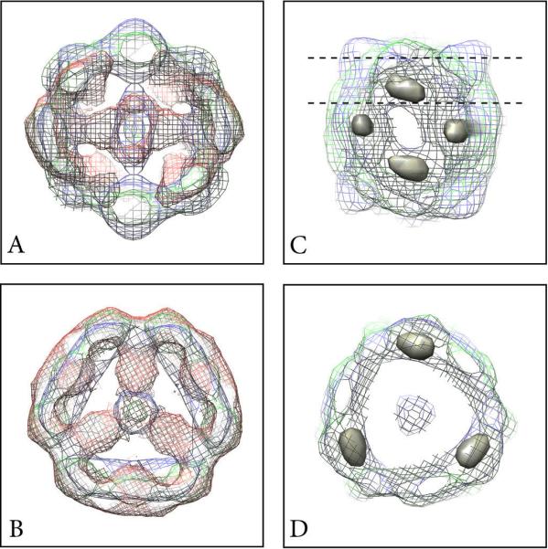
Differences between the maps of MUC2D3CysD1-MG (red), MUC2D3CysD1-M (blue), and MUC2D3 (green). Slice through the center of the map from the side along the two-fold axis (A) and from the top (B). The red non-overlapping domains in A and B stretching towards the center correspond to the difference between the GFP containing part and the other two lacking this. Positions of the strongest positive domains (surface rendered in grey) obtained from the difference between the MUC2D3CysD1-M and MUC2D3 maps as seen in a side view (C). The dashed lines indicate the slice shown as a top view in (D).
Discussion
A model for the packing of MUC2 in secretory vesicles of goblet cells and the mechanism for its release, unfolding and expansion was suggested earlier [7]. Its properties were based on combining biochemical and electron microscopy studies with related knowledge obtained for the VWF [7; 13]. Instead of forming helical rods, observed for VWF as a consequence of C-terminal dimerization and subsequent N-terminal dimerization [11; 12; 16], it was found that the MUC2-N terminal protein formed trimers [6] and that these assembled into N-terminal concatenated polygons having six sides (other polygons were also observed) in the presence of Ca2+ and at pH 6 [7]. From TEM projection maps it was suggested that the N-terminal hexagons may be assembled from six repeating units, where each of these units consists of three D1-D2 peptides and one disulfide-linked D'D3 trimer, where the D'D3 part constitutes the vertices in a polygon [7].
In the present study, aiming for a more detailed understanding at the molecular level, we have shown that, with the exception for the CysD domain, VWF and MUC2 N-terminal parts have substantial sequence homologies in the conserved regions (Suppl Fig. S1). As for VWF, the MUC2 N-terminal D1, D2, and D3 domains are subdivided into VWD (the largest part), C8, TIL, and E modules [15] (Fig. 1A and Suppl Fig. S1). Since the different D domains in the MUC2 N-terminus have a similar subdivision pattern, we decided to concentrate structural studies to the D'D3 domain. This moiety, constituting the central part of the N-terminal disulfide-bonded trimer [6] and the corners of the polygon formed at high Ca2+/low pH [7], is itself largely proteolytically stable [6], and insensitive to pH- and Ca2+-dependent interactions [7].
Three constructs of the D'D3 domain were used in this study, namely, MUC2D3CysD1-MG including the CysD1 domain and tagged with Myc and GFP, the MUC2D3CysD1-M without the GFP and MUC2D3 without both Myc, GFP and the CysD domain (Fig. 1). Three-dimensional reconstructions of the three different recombinant proteins all adopted hollow cage-like structures (Fig. 2). Whereas the MUC2D3CysD1-MG included a dense core structure inside the cage, the other two GFP-lacking constructs had weaker density in the middle when viewed from the top (Fig. 3B). Importantly, the GFP-containing fusion protein had an elongated shape while the other two constructs were more round-shaped when observed along the two-fold axis (Fig. 2 and Suppl. Figs. S3, S4). The structural comparisons suggest that the GFP tags are positioned so that they extend from the periphery of the complex towards the center with their center of masses positioned along the central section at the interface between the two hemispheres of the structure (Fig. 3B). Interactions introduced by the presence of GFP are also likely to explain why the side view is significantly more flat for MUC2D3CysD1-MG than for the other two constructs and for its slightly larger diameter.
According to biochemical data obtained earlier for the whole MUC2 N-terminal part [7], as well as the masses estimated from gel filtration, 780 kDa (MUC2D3CysD1-MG) and 600 kDa (MUC2D3CysD1-M and MUC2D3), together with EM data, it is likely that the small donuts are composed of hexamers (two trimers in a D3 conformation). This interpretation is also in accordance with the mass of the reduced single monomers as determined by gel electrophoresis (Fig. 1C). As the three MUC2D3 proteins were constructed before a more accurate subdomain prediction was available, these included half a TIL-2 domain and E-2 from the D2 assembly in addition to the subdomains of D'D3. This then also included three unpaired cysteine pairs that could influence the packing, but control specimens (Suppl. Fig. S2E) have shown similar assemblies.
The map of the MUC2D3CysD1-M construct was used to extract an asymmetric contiguous monomeric region (Fig. 4). The three monomers occupying the upper and the lower hemisphere of the complete hexameric complex can be described as forming a left-handed protein bundle when viewed along the three-fold axis (handedness analysis could not be performed at the present resolution level but comparisons showed that the three maps had the same handedness). The three monomers are connected around the poles of the structure while the most prominent connection between the upper and lower parts is positioned at the two-fold axis as shown in the side view in Fig. 4. As seen from the top each monomer is enclosed in an area of 95 × 65 Å. This was similar to class averages from EM projections of a recombinant VWF blood glycoprotein N-terminal construct with the D'D3 domain showing that each monomer had a bulbous crescent-like appearance with an average diameter of approximately 65 Å [14]. Furthermore for VWF, a dimeric interface between adjacent D'D3 domains was observed at pH 6.2 but not at pH 7.4.
Fig. 4.

Segmentation of MUC2D3CysD1-M into monomeric regions of contiguous density. The maps are shown at a high threshold value from the top (top) and from the side along the two-fold axis. This symmetry element crosses a density-rich region on one side (towards the viewer in this figure), while the opposite side along this line is density-deficient for both this protein construct and MUC2D3 (cf Fig. 3). The three monomers occupying the upper and the lower hemisphere, respectively, can be described as forming a left-handed (absolute hand not determined) protein bundle when viewed along the three-fold axis. Those three monomers are connected around the poles of the structure while the most prominent connection between the upper and lower parts is positioned at the two-fold axis as shown in the side view. Scale bar 20 Å.
By comparison to the recently established subdomain structure of the VWF we were able to confirm that the D'D3 domain of MUC2 included several smaller domains [15]; namely, TIL’, E’, VWD3, C8-3, TIL-3 and E-3 (Fig. 1A and Suppl Fig. S1). From our maps we could extract subregions of each monomer based on the subdivisions revealed at high density threshold levels (Fig. 5). As the monomer has an elongated shape, it is likely that the N- and C-termini are placed towards the ends of the rods. The proposed assignment in Fig. 5A positions the suggested VWD3 multimer assembly motif as well as the antibody binding sequence (Fig. 1A) in the region around the three-fold axis [17]. The gold label attached to the antibodies was observed on the three-fold axis in top views of the particles (Suppl Fig. S2). In the VWF the two cysteines involved in interdimer disulfide bond stabilization are in the C8-3 and TIL-3 subdomains [15]. Interestingly, our sequence alignments of VWF and MUC2 revealed that the VWF contained an odd number of cysteines (eleven each) in C8-3 and TIL-3, whereas MUC2 had an even number of cysteines in these two domains (Suppl Fig. S1). Thus it may be speculated that in MUC2 the cysteines in those two subdomains form intramolecular disulfide bonds. The proposed designation of the CysD1 domain is close to the two-fold axis and it probably extends towards the interior of the structure. Indeed one of the unique strongest peaks as calculated from the difference between the MUC2D3CysD1-M and MUC2D3 maps is located in this region (the two central peaks in Fig. 3C).
Fig. 5.

Segmentation of one MUC2D3CysD1-M monomer into subregions. The maps are shown at a high threshold value. (A) View along a direction that is slightly tilted from the side views as shown in Figs. 2 and 4. A possible subdomain organization has been depicted. (B) and (C) Location of the GFP domain from MUC2D3CysD1-MG relatively to the model proposed in A. The MUC2D3CysD1-MG map shown in mesh representation from the side (B) and from the top (C) has a strong domain also at the two-fold axis end that is lacking density in the maps from the other two constructs deficient of GFP. One monomer has been subdivided into domains while the others are shown with a grey mesh representation.
In MUC2D3CysD1-MG the GFP was fused to the C-terminus of the complex and this unique density is located close to the proposed CysD1-M domain (Figs. 5B, C). Thus, we predict that this is the start of the mucin-domain in full-length MUC2. The density centered on the three-fold axis at the poles of the present 3D structures would then harbor the connections to the D1D2 domains (Figs. 5A and 6A, arrows with filled heads). Under the assumption that the present dimer of trimer arrangement of the N-terminal D domains is applicable also for full-length MUC2, we can now extend our previous model of how two MUC2 mucin polymers are packed. In the previous model, the N-termini were forming hexameric polygonal structures that were concatenated to give a surface on which the C-terminal reminder of the molecule including the long rod-like mucin domains were standing [7]. We then assumed that each vertex was composed of one N-terminal trimer. However, the present D'D3 structure is made up of two covalent N-terminal trimers, where one is turned by 180° and they meet sideways. This should suggest that the vertices were not built by one N-terminal trimer, but instead of two. This will also mean that the C-terminal remainders of the MUC2 mucin are pointing out on each side of the N-terminal concatenated polygon platform (Fig. 6B and Suppl Fig. S8A, arrows with open heads,). It should be noted that having two N-terminal trimers arranged up-side down and held together by covalent disulfide bonds within one trimer (most likely in the VWD3 domain) and by non-covalent forces between two trimer hemispheres, is compatible with our previously presented packing model and is only an extension to this model [7]. In our previous model of how the MUC2 mucin is packed inside the goblet cell granulae, we only included one N-terminal concatenated polygon platform as we did not have any indications of how each platform was arranged relative to the next one. Upon release, the Ca2+-ions are removed and the pH raised by sodium bicarbonate. As discussed, it is possible that the packed N-terminal polygonal structures are arranged in pairs of two such that they are turned by 180° relative to each other and the N-terminal concatenated polygons meet on one side and the C-terminal remainders including the mucin domains at the other side (Fig. 6, Suppl Fig. S8). As it is not likely, not even possible, that the unfolded MUC2 net can turn around this also means that every second unfolded net is turned up-side down. This advanced model is further emphasizing that the different sheets in the inner mucus layer may interact and, in addition to the CysD domains, further organize the inner stratified mucus layer [18; 19]. Therefore the MUC2 mucin exhibits a highly organized supramolecular topology during packing and release and not a random coil conformation.
Fig. 6.

Model of the packing of full length MUC2. (A) and (B) Model of a six-sided polygon using the present 3D map of MUC2D3CysD1-M at the vertices and with a linker region corresponding to D1D2 between them (rectangles with filled arrow heads). In (A) the view is from the top and in (B) slightly tilted. For 3D modeling guidance the crystal structure of the coiled-coil domain of C. elegans SAS-6 (pdb 4GKW) was used as an arbitrary linear molecular template. It was also used to depict the mucin domains extending perpendicular to the hexagon (colored coiled-coils in A and rectangles with open arrow heads added in B). For clarity, mucins are shown for the MUC2D3CysD1-M map only. For comparison the averaged projection map of six-sided polygons [7] is shown in C. The structures are shown at the same scale and the distance between the vertices is 170 Å.
Materials and Methods
Construction of pSMUC2D3CysD1-MG, pSMUC2D3CysD1-M, pSMUC2D3 and pS6xHisMUC2D3-M Expression plasmids
pSNMUC2-MG, a plasmid expressing the N-terminal domains of human MUC2 fused to a Myc tag and GFP [6], was used for the construction of MUC2D3 expressing vectors as follows. The sequence encoding the D1, D2 and D’ domains was excised by cutting with XhoI and religating, utilizing a natural XhoI site in the MUC2 sequence located between the D’ and D3 domains and a XhoI site in the vector located upstream of the MUC2 gene. This construct had been made before the domain borders were redefined for the D assemblies of the MUC2-related protein VWF as recently described [15]. An extra G had to be inserted into the coding sequence by Quikchange™ mutagenesis (Stratagene) to correct the reading frame, using the primers 5’-ggccaggcgcggccgtacgaagc-3’ and 5’-gcttcgtacggccgcgcctggcc-3’. The resulting plasmid pSMUC2D3CysD1-MG encoded the D3 and CysD1 domains of MUC2 (amino acids 689-1397), fused to Myc and GFP, with an Ig κ signal peptide for secretion.
To remove GFP from the construct, an AAG→TAG mutation was introduced at amino acid 2 of the GFP gene in pSMUC2D3CysD1-MG by Quikchange™ mutagenesis using the primers 5’-cagttttatcaacaactccctaggtgtgctgcctctggtctg-3’ and 5’-cagaccagaggcagcacacctagggagttgttgataaaactg-3’, to get the plasmid pSMUC2D3CysD1-M. Similarly, an AAG→TAG mutation was introduced at MUC2 amino acid 1300, using the primers 5’-ggtgccaccatggtgtcctagggcgaggagctgttc-3’and 5’-gaacagctcctcgccctaggacaccatggtggcacc-3’to remove the sequence encoding both the CysD1 domain, Myc tag and GFP in the resulting plasmid pSMUC2D3. Oligonucleotides were from Eurofins MWG, Germany, where DNA sequencing of all modified vectors was also performed.
The expression vector pS6xHisMUC2D3-M encoding only the D3 domain and not the additional TIL-2 and E-2 domains was also constructed. The DNA encoding the D3 domain (amino acids 857-1296) was amplified from pSNMUC2-MG with primers that also encoded BamHI and KpnI sites that could be used to clone the amplified fragment into the desired expression vector. The resulting protein MUC2D3ΔTIL2E2 was expressed with an Ig ϰ light chain signal peptide, an N-terminal His6-tag and a C-terminal myc tag.
Production of Recombinant MUC2D3CysD1-MG and MUC2D3CysD1-M in CHO-Lec 3.2.8.1 Cells
CHO-Lec 3.2.8.1 cells (kindly provided by Prof. Pamela Stanley, NY) were grown in Iscove's Modified Dulbecco's Medium (IMDM) with 10 % FBS (Lonza, Verviers, Belgium) at 37 °C with 5 % CO2. Transfection of CHO-Lec 3.2.8.1 cells with pSMUC2D3CysD1-MG or pSMUC2D3CysD1-M was performed using Lipofectamine 2000 (Invitrogen, Carlsbad, CA) in 6-well plates in accordance with the manufacturer's instructions. G418 (Invitrogen, Carlsbad, CA) at 250 μg/ml was added for selection three days after transfection. Generation of stably-producing clones was performed by seeding transfected cells into 9 cm Petri dishes to obtain separate colonies and then screening for secreted recombinant protein among isolated clones grown in 96- well plate. One high-producing clone for each protein construct was adapted to grow in suspension [20] using ProCHO-4 with 1xProHT, 4 mM L-glutamine (Lonza, Verviers, Belgium) with 250 μg/ml of G418 in 250 ml spinner flasks. FBS concentration was initially 2 % and could be reduced stepwise to 0 % after the cells reached 1 × 10⁶/ml in the presence of 2 % FBS. The adaptation took 2.5 months. Collection of 3.5 l of cell supernatant with recombinant MUC2D3CysD1-MG protein or 2.5 l of cell supernatant with recombinant MUC2D3CysD1-M, respectively, was performed in spinner flasks. At harvest the cell suspension was centrifuged at 200 × g for 5 min at room temperature and the supernatant was stored at 4 °C with 0.05 % NaN3.
Production of Recombinant MUC2D3 and MUC2D3ΔTIL2E2 in CHO-S and CHO-Lec 3.2.8.1-S Cells
Since stable MUC2D3-producing clones could not be obtained in CHO-Lec 3.2.8.1 cells the production was performed by transient transfection of suspension cells in bioreactors. CHO-Lec 3.2.8.1 cells are usually grown adherently in IMDM with 10% FBS and had to be adapted to serum-free suspension growth in FreeStyle™ CHO medium with 8 mM L-glutamine (Invitrogen, Carlsbad, CA) in order to perform the transfection. This adaptation was achieved by initial cultivation in 250 ml spinner flask in a mixture of 50% FreeStyle™ CHO medium with 8 mM L-glutamine and 50% IMDM supplemented with FBS (10%), L-aspargine (36 mg/l), L-arginine-HCl (116 mg/l), L-glutamine (290 mg/l), Napyruvate (110 mg/l), folic acid (10 mg/l) and β-mercaptoethanol (3.49 μl/l). Since the cells showed a tendency to form aggregates a new composition of 25% IMDM with 10 % FBS and supplements as above was mixed with 25% ProCHO-4 with 1xProHT, 4 mM L-glutamine (Lonza, Verviers, Belgium) and 50% Freestyle with 8 mM L-glutamine. IMDM could be abandoned after two passages and the medium thereafter consisted of 60% Freestyle™ CHO with 8 mM L-glutamine and 40% ProCHO-4 with 1xProHT and 4 mM L-glutamine. The cells were then passaged to 0.3 × 10⁶ cells/ml every three to five days (viability kept above 90%). The amount of ProCHO-4 medium could be reduced to 0 % stepwise during 2 months and then the cells grew to 1.5-2 × 10⁶ with a doubling rate of 0.5-1/day. The adapted cells were designated CHO-Lec 3.2.8.1-S (S=suspension).
For production of the MUC2D3 protein a one liter Biobundle bioreactor controlled by an ADI 1010 Bio Controller and an ADI 1025 Bio Console (Applikon Biotechnology, Schiedam, The Netherlands) was used. The system was set up with a heating blanket for temperature control and 0.3 M NaOH and CO2 (g) for pH control. The dO2 was set at 40% of air saturation and was adjusted with a mixture of N2 and O2 with a maximum flow of 120 ml/min introduced via sparger. At day one CHO-S cells (Invitrogen, Carlsbad, CA) or CHO-Lec 3.2.8.1-S cells in log phase were introduced into the reactor to a concentration of 0.45 × 10⁶ cells/ml in 500 ml Freestyle™ CHO with 8 mM L-glutamine. At day two the volume was adjusted to 1-1.3 × 10⁶ cells/ml and transfection with NovaCHOice transfection kit (Merck, Nottingham, UK) was performed according to the manufacturer's instructions. Four hours after transfection the temperature was decreased to 31°C. Production was finished when the viability determined with Trypan blue went below 75% which was after 72-96 h for CHO-Lec 3.2.8.1-S cells and 96-168 h for CHO-S cells. The supernatant was harvested by centrifugation for 10 min at 200 × g at room temperature and then immediately stored at 4°C with 0.05% NaN3. Two batches of approximately 500 ml each were made in CHO-S and CHO-Lec 3.2.8.1-S, respectively.
To produce MUC2D3ΔTIL2E2, CHO-Lec 3.2.8.1-S cells were transfected with pS6xHisMUC2D3-M as described above, but using 130×106 cells cultured in an Erlenmeyer flask in a CO2 incubator, and the protein was harvested after 48h.
Purification of MUC2D3CysD1-MG and MUC2D3CysD1-M from Culture Medium of CHO-Lec 3.2.8.1 Cells and MUC2D3 from Culture Medium of CHO-Lec 3.2.8.1-S and CHO-S Cells
Spent culture medium (3.5 litres for MUC2D3CysD1-MG, 2.5 litres for MUC2D3CysD1-M and 1 litre for MUC2D3 from CHO-Lec 3.2.8.1-S and CHO-S) containing recombinant protein was filtered (0.45 μm Mini Capsule, PALL) and concentrated by Tangential Flow Filtration (Pellicon™-2 system, Millipore) with two 10 kDa PLCGC filters. A buffer change was performed when the volume of the concentrate was reduced to 400 ml by addition of 400 ml of 20 mM Tris/HCl (pH 8) with 0.05 % NaN3 followed by another reduction of the volume to 400 ml. The procedure was repeated 5 times and the concentrate volume was finally reduced to 150-350 ml that was filtered (Durapore® Membrane Filter, 0.22 μm GVWP, Millipore) and loaded onto a Mono Q™ 5/50 GL anion exchange column (5 mm × 50 mm, GE) at 0.5 ml/min using an Äkta HPLC (GE). Before sample application the column was washed with buffer B (20 mM Tris/HCl (pH 8), 1 M NaCl) and then equilibrated with buffer A (20 mM Tris/HCl (pH 8)). The bound components were then eluted in a linear gradient of 0-40 % buffer B, collected into 60 fractions (1 ml/fraction) and analyzed by reducing SDS/PAGE, silver staining and western blotting using an affinity-purified rabbit anti-MUC2-N3 antibody [7]. MUC2D3 from CHO-Lec 3.2.8.1-S or MUC2D3 from CHO-S was filtered (Durapore® Membrane Filter, 0.22 μm GVWP, Millipore) and loaded onto a Mono Q™ HR 10/10 anion exchange column (10 mm x 100 mm, GE) at 4 ml/min using an Äkta HPLC (GE). Before sample application the column was washed with buffer B (20 mM Tris/HCl (pH 8), 1 M NaCl) and then equilibrated with buffer A (20 mM Tris/HCl (pH 8)). The bound components were then eluted in a linear gradient of 0-100% buffer B, collected into 20 fractions (4 ml/fraction) and analyzed by reducing SDS/PAGE, silver staining and western blotting using an affinity-purified rabbit anti-MUC2-N3 antibody [7].
The MUC2D3CysD1-MG- and MUC2D3CysD1-M-containing fractions (8 × 1 ml) or MUC2D3-containing fractions (3 × 4 ml) (from CHO-Lec 3.2.8.1-S) or (2 × 4 ml) (from CHO-S) were then applied separately onto a Superose 6 HR 10/30 gel filtration column (GE) that was equilibrated with 20 mM Tris/HCl (pH 8), 150 mM NaCl and eluted into 24 fractions (1 ml/fraction) at 0.2 ml/min using an Äkta HPLC (GE). The column void volume was 7.3 ml and the standards thyroglobulin, ferritin, aldolase, ovalbumin and ribonuclease A eluted at 11.9 ml, 13.6 ml, 15.7 ml, 16.3 ml and 18.3 ml, respectively. The collected fractions were analyzed by reducing SDS/PAGE, silver staining and western blotting using an affinity-purified anti-MUC2-N3 antibody [7]. The fractions containing MUC2D3CysD1-MG (7 ml), MUC2D3CysD1-M (7 ml) or MUC2D3 (2.5 ml from Lec 3.2.8.1-S, 0.5 ml from CHO-S) were combined and then concentrated to 250 μl (1.1 mg/ml for MUC2D3CysD1-MG), 100 μl (2.1 mg/ml for MUC2D3CysD1-M) or 100 μl (0.3 mg/ml for MUC2D3 from CHO-Lec 3.2.8.1-S, 0.4 mg/ml for MUC2D3 from CHO-S) by ultrafiltration (Vivaspin 6 PES, molecular-mass cut-off of 10 kDa, Sartorius).
MUC2D3ΔTIL2E2 was purified from CHO-Lec 3.2.8.1 transfection culture supernatant that had been dialyzed against 20 mM phosphate buffer pH 7.4 with 0.5 M NaCl, using a 1 ml HiTrap chelating column loaded with CoCl2.After washing the column with 20 mM imidazole, the protein was eluted in 200 mM imidazole and pooled fractions were dialyzed against 20 mM Tris-HCl, pH 8.0, 150 mM NaCl. The concentration of the purified protein was 0.103 mg/ml.
Gel Electrophoresis
SDS/PAGE was performed as described previously [21]. Precision protein standards (Bio-Rad Laboratories) were used as markers. Silver staining was carried out as described previously [22]. Western blotting was performed as described previously [23]. After transfer the membrane was blocked in 5% skimmed milk powder in PBS with 0.1% Tween 20 and incubated with an affinity-purified rabbit anti-MUC2-N3 antibody [7]. The membrane was then treated with AP (alkaline phosphatase)-conjugated goat anti-rabbit IgG (Southern Biotech) and developed with NBT (Nitro Blue Tetrazolium)/BCIP (5-bromo-4-chloro-3-indolyl phosphate) (Promega).
Negative Stain and Immuno Gold-Labeling
The samples (80-135μg/ml) in 20 mM Tris/HCl (pH 8) and 150 mM NaCl were centrifuged at 17,000 × g for 20 min at 4°C. The supernatant was incubated for 2 h at room temperature. Aliquots (4 μl) were adsorbed onto glow-discharged carbon-coated copper grids (400 mesh, Analytical Standards), washed twice with a drop of water and stained with a drop of 2% (w/v) uranyl acetate for 30 s before blotting and air-drying. In order to check that the particles consisted of the D'D3 domain, immuno gold-labeling of the D3 domain was performed using a gold-labeled affinity-purified anti-MUC2-N3 antibody (Gold-labeled PurαMUC2N3 without BSA in 20 mM Mes (pH 6.2), 150 mM NaCl, 10 mM CaCl2) as described before [7]. The rabbit anti-MUC2-N3 antiserum was raised against the synthetic peptide CPKDRPIYEEDLKK of the D3 domain. The protein construct, 135μg/ml (in 20 mM Tris/HCl (pH 8.0), 150 mM NaCl), was incubated at room temperature for 1.5 h. Thereafter the antibody was added directly to the sample. The sample was adsorbed onto glow-discharged carbon-coated gold grids and negatively stained as above.
Transmission Electron Microscopy (TEM)
For MUC2D3CysD1-MG images were recorded with an FEI CM 120 electron microscope operating at an accelerating voltage of 120 kV onto Kodak SO-163 films at a magnification of 45,000 ×. The defocus values were in the range of 0.5-1.5 μm. Films were developed in concentrated Kodak D-19 developer for 12 min. To determine the quality of the micrographs, optical diffraction was used. Micrographs where digitized using a Zeiss SCAI scanner with a spacing corresponding to ~ 3.11 Å/pixel at the specimen level. For MUC2D3CysD1-M and MUC2D3 data was collected by the use of a Jeol JEM2100F field emission gun transmission electron microscope operating at 200 kV. Micrographs were recorded at a magnification of 56,600 × corresponding to ~2.67 Å/pixel on a 4K × 4K CCD camera (Tietz Video and imaging processing system). Defocus values were in the range of 1.5-2.5 μm. All images were recorded with an electron dose of 12-15 e− per Å2.
Image Processing and Single Particle Reconstruction
For all three constructs the programs used for image processing of electron micrographs and surface rendering of the 3D-models were EMAN1 [24]. From the micrographs particles in different orientations were selected using the program BOXER. For MUC2D3CysD1-MG 8635 particles from 75 micrographs (film) were picked and 86 % contributed to the final map. Corresponding figures for MUC2D3CysD1-M and MUC2D3 were 7248/463(CCD)/75 % and 7321/83(CCD)/83 % respectively. The contrast transfer function (CTF) was corrected, based on an objective lens spherical aberration coefficient of 2 mm. The defocus determination and CTF-phase-flipping was performed using the ctfit program to ensure the contrast to be consistent at all spatial frequencies.
For all three constructs initial models for subsequent refinement were generated applying rotational symmetry, C3, from which a 3D-model was constructed from two class averages representing two orthogonal views of the molecule. The determination of the symmetry of the molecules and initial models for 3D reconstruction were based on class averages, generated by the refine2d.py program in EMAN1 (Suppl. Fig. S3) and knowledge from the biochemistry.
In order to produce references for particle classification, the initial 3D-model was re-projected to generate 2D projection images. After this classification, particles were mutually aligned and averaged to generate a set of class averages, which were combined to form a new improved 3D-model in the refine program in EMAN1. This procedure was iterated until the 3D reconstruction converged. D3 symmetry was applied during the reconstruction. The determination of the resolution of the 3D reconstructions was based on three-dimensional Fourier shell correlation (FCS) (i.e. an even odd test procedure of EMAN). The final results were lowpass filtered to approx. 12 Å to remove noise, without changing the structural information at the estimated resolution of ~ 18 Å (see below).
All visualization was done using Chimera [25]. The surface contour level of the three constructs was determined using a threshold level based on a molecular mass of 780 kDa (MUC2D3CysD1-MG) and 600 kDa (MUC2D3CysD1-M and MUC2D3) (Fig. 1C) and a molecular density of 1.35 g/cm3 [26]. However this was performed with approximations only, due to artifacts of suspected shrinking of the molecule during the negative staining procedure. The map2map program from the Situs package [27] was used to convert the maps produced by EMAN1 to the ccp4 format for continued processing [28]. As guidance for segementation of monomers and subdomains the “place atom at pointer” facility in Coot [29] was used to fix coordinates in the maps. Masks based on selected “atoms” were produced using the ncsmask program from the ccp4 package and the masks were subsequently multiplied by the experimental maps to outline the desired segments.
2D crystals were occasionally observed for the MUC2D3CysD1-MG specimen following plunge freezing in liquid ethane and cryoEM using a Gatan liquid nitrogen cryo holder inserted into a Jeol 2100F electron microscopes. Electron crystallographic processing was performed using the MRC image processing suite [30] and the Ximdisp visualization tool [31]. Four of the processed individual images merged with an overall phase residual to 14 Å of 32° and were used for calculation of the projection map. The ALLSPACE program [32] suggested p2 projection symmetry (average deviation from 0° or 180° was 18.7°) and maps were calculated both with and without imposed two-fold symmetry.
Supplementary Material
Acknowledgements
This work was supported by the Swedish Research Council, The Swedish Cancer Foundation, The Knut and Alice Wallenberg Foundation, Erica Lederhausen's Foundation, RfCF Research Foundation, IngaBritt and Arne Lundberg Foundation, Sahlgren's University Hospital (LUA ALF), Karolinska Institutet Center for Biosciences, Wilhelm and Martina Lundgren's Foundation, Torsten och Ragnar Söderbergs Foundations, The Sahlgrenska Academy, National Institute of Allergy and Infectious Diseases (U01AI095473), and The Swedish Foundation for Strategic Research - The Mucus-Bacteria-Colitis Center (MBC) of the Innate Immunity Program.
References
- 1.Lang T, Hansson GC, Samuelsson T. Gel-forming mucins appeared early in metazoan evolution. Proc Natl Acad Sci U S A. 2007;104:16209–14. doi: 10.1073/pnas.0705984104. [DOI] [PMC free article] [PubMed] [Google Scholar]
- 2.Gum JR, Jr., Hicks JW, Toribara NW, Siddiki B, Kim YS. Molecular cloning of human intestinal mucin (MUC2) cDNA. Identification of the amino terminus and overall sequence similarity to prepro-von Willebrand factor. J Biol Chem. 1994;269:2440–6. [PubMed] [Google Scholar]
- 3.Thornton DJ, Rousseau K, McGuckin MA. Structure and function of the polymeric mucins in airways mucus. Annu Rev Physiol. 2008;70:459–86. doi: 10.1146/annurev.physiol.70.113006.100702. [DOI] [PubMed] [Google Scholar]
- 4.Johansson ME, Phillipson M, Petersson J, Velcich A, Holm L, Hansson GC. The inner of the two Muc2 mucin-dependent mucus layers in colon is devoid of bacteria. Proc Natl Acad Sci U S A. 2008;105:15064–9. doi: 10.1073/pnas.0803124105. [DOI] [PMC free article] [PubMed] [Google Scholar]
- 5.Lidell ME, Johansson ME, Morgelin M, Asker N, Gum JR, Jr., Kim YS, Hansson GC. The recombinant C-terminus of the human MUC2 mucin forms dimers in Chinese-hamster ovary cells and heterodimers with full-length MUC2 in LS 174T cells. Biochem J. 2003;372:335–45. doi: 10.1042/BJ20030003. [DOI] [PMC free article] [PubMed] [Google Scholar]
- 6.Godl K, Johansson ME, Lidell ME, Morgelin M, Karlsson H, Olson FJ, Gum JR, Jr., Kim YS, Hansson GC. The N terminus of the MUC2 mucin forms trimers that are held together within a trypsin-resistant core fragment. J Biol Chem. 2002;277:47248–56. doi: 10.1074/jbc.M208483200. [DOI] [PubMed] [Google Scholar]
- 7.Ambort D, Johansson ME, Gustafsson JK, Nilsson HE, Ermund A, Johansson BR, Koeck PJ, Hebert H, Hansson GC. Calcium and pH-dependent packing and release of the gel-forming MUC2 mucin. Proc Natl Acad Sci U S A. 2012;109:5645–50. doi: 10.1073/pnas.1120269109. [DOI] [PMC free article] [PubMed] [Google Scholar]
- 8.Round AN, Rigby NM, Garcia de la Torre A, Macierzanka A, Mills EN, Mackie AR. Lamellar structures of MUC2-rich mucin: a potential role in governing the barrier and lubricating functions of intestinal mucus. Biomacromolecules. 2012;13:3253–61. doi: 10.1021/bm301024x. [DOI] [PubMed] [Google Scholar]
- 9.Gustafsson JK, Ermund A, Ambort D, Johansson ME, Nilsson HE, Thorell K, Hebert H, Sjovall H, Hansson GC. Bicarbonate and functional CFTR channel are required for proper mucin secretion and link cystic fibrosis with its mucus phenotype. J Exp Med. 2012;209:1263–72. doi: 10.1084/jem.20120562. [DOI] [PMC free article] [PubMed] [Google Scholar]
- 10.Sadler JE. Biochemistry and genetics of von Willebrand factor. Annu Rev Biochem. 1998;67:395–424. doi: 10.1146/annurev.biochem.67.1.395. [DOI] [PubMed] [Google Scholar]
- 11.Wagner DD, Saffaripour S, Bonfanti R, Sadler JE, Cramer EM, Chapman B, Mayadas TN. Induction of specific storage organelles by von Willebrand factor propolypeptide. Cell. 1991;64:403–13. doi: 10.1016/0092-8674(91)90648-i. [DOI] [PubMed] [Google Scholar]
- 12.Katsumi A, Tuley EA, Bodo I, Sadler JE. Localization of disulfide bonds in the cystine knot domain of human von Willebrand factor. J Biol Chem. 2000;275:25585–94. doi: 10.1074/jbc.M002654200. [DOI] [PubMed] [Google Scholar]
- 13.Huang RH, Wang Y, Roth R, Yu X, Purvis AR, Heuser JE, Egelman EH, Sadler JE. Assembly of Weibel-Palade body-like tubules from N-terminal domains of von Willebrand factor. Proc Natl Acad Sci U S A. 2008;105:482–7. doi: 10.1073/pnas.0710079105. [DOI] [PMC free article] [PubMed] [Google Scholar]
- 14.Zhou YF, Eng ET, Nishida N, Lu C, Walz T, Springer TA. A pH-regulated dimeric bouquet in the structure of von Willebrand factor. Embo J. 2011;30:4098–4111. doi: 10.1038/emboj.2011.297. [DOI] [PMC free article] [PubMed] [Google Scholar]
- 15.Zhou YF, Eng ET, Zhu J, Lu C, Walz T, Springer TA. Sequence and structure relationships within von Willebrand factor. Blood. 2012;120:449–458. doi: 10.1182/blood-2012-01-405134. [DOI] [PMC free article] [PubMed] [Google Scholar]
- 16.Sadler JE. von Willebrand factor assembly and secretion. J Thromb Haemost. 2009;7(Suppl 1):24–7. doi: 10.1111/j.1538-7836.2009.03375.x. [DOI] [PubMed] [Google Scholar]
- 17.Perez-Vilar J, Hill RL. The structure and assembly of secreted mucins. J Biol Chem. 1999;274:31751–4. doi: 10.1074/jbc.274.45.31751. [DOI] [PubMed] [Google Scholar]
- 18.Johansson ME, Ambort D, Pelaseyed T, Schutte A, Gustafsson JK, Ermund A, Subramani DB, Holmen-Larsson JM, Thomsson KA, Bergstrom JH, van der Post S, Rodriguez-Pineiro AM, Sjovall H, Backstrom M, Hansson GC. Composition and functional role of the mucus layers in the intestine. Cell Mol Life Sci. 2011;68:3635–41. doi: 10.1007/s00018-011-0822-3. [DOI] [PMC free article] [PubMed] [Google Scholar]
- 19.Ambort D, van der Post S, Johansson ME, Mackenzie J, Thomsson E, Krengel U, Hansson GC. Function of the CysD domain of the gel-forming MUC2 mucin. Biochem J. 2011;436:61–70. doi: 10.1042/BJ20102066. [DOI] [PMC free article] [PubMed] [Google Scholar]
- 20.Thomsson E, Persson L, Grahn A, Snall J, Ekblad M, Brunhage E, Svensson F, Jern C, Hansson GC, Backstrom M, Bergstrom T. Recombinant glycoprotein E produced in mammalian cells in large-scale as an antigen for varicellazoster-virus serology. J Virol Methods. 2011;175:53–9. doi: 10.1016/j.jviromet.2011.04.014. [DOI] [PubMed] [Google Scholar]
- 21.Laemmli UK. Cleavage of structural proteins during the assembly of the head of bacteriophage T4. Nature. 1970;227:680–5. doi: 10.1038/227680a0. [DOI] [PubMed] [Google Scholar]
- 22.Swain M, Ross NW. A silver stain protocol for proteins yielding high resolution and transparent background in sodium dodecyl sulfate-polyacrylamide gels. Electrophoresis. 1995;16:948–51. doi: 10.1002/elps.11501601159. [DOI] [PubMed] [Google Scholar]
- 23.Towbin H, Staehelin T, Gordon J. Electrophoretic transfer of proteins from polyacrylamide gels to nitrocellulose sheets: procedure and some applications. Proc Natl Acad Sci U S A. 1979;76:4350–4. doi: 10.1073/pnas.76.9.4350. [DOI] [PMC free article] [PubMed] [Google Scholar]
- 24.Ludtke SJ, Jakana J, Song JL, Chuang DT, Chiu W. A 11.5 A single particle reconstruction of GroEL using EMAN. J Mol Biol. 2001;314:253–62. doi: 10.1006/jmbi.2001.5133. [DOI] [PubMed] [Google Scholar]
- 25.Pettersen EF, Goddard TD, Huang CC, Couch GS, Greenblatt DM, Meng EC, Ferrin TE. UCSF Chimera--a visualization system for exploratory research and analysis. J Comput Chem. 2004;25:1605–12. doi: 10.1002/jcc.20084. [DOI] [PubMed] [Google Scholar]
- 26.Matthews BW. Solvent content of protein crystals. J Mol Biol. 1968;33:491–7. doi: 10.1016/0022-2836(68)90205-2. [DOI] [PubMed] [Google Scholar]
- 27.Wriggers W. Using Situs for the integration of multi-resolution structures. Biophys Rev. 2:21–27. doi: 10.1007/s12551-009-0026-3. [DOI] [PMC free article] [PubMed] [Google Scholar]
- 28.Winn MD, Ballard CC, Cowtan KD, Dodson EJ, Emsley P, Evans PR, Keegan RM, Krissinel EB, Leslie AG, McCoy A, McNicholas SJ, Murshudov GN, Pannu NS, Potterton EA, Powell HR, Read RJ, Vagin A, Wilson KS. Overview of the CCP4 suite and current developments. Acta Crystallogr D Biol Crystallogr. 2011;67:235–42. doi: 10.1107/S0907444910045749. [DOI] [PMC free article] [PubMed] [Google Scholar]
- 29.Emsley P, Cowtan K. Coot: model-building tools for molecular graphics. Acta Crystallogr D Biol Crystallogr. 2004;60:2126–32. doi: 10.1107/S0907444904019158. [DOI] [PubMed] [Google Scholar]
- 30.Crowther RA, Henderson R, Smith JM. MRC image processing programs. J Struct Biol. 1996;116:9–16. doi: 10.1006/jsbi.1996.0003. [DOI] [PubMed] [Google Scholar]
- 31.Smith JM. Ximdisp--A visualization tool to aid structure determination from electron microscope images. J Struct Biol. 1999;125:223–8. doi: 10.1006/jsbi.1998.4073. [DOI] [PubMed] [Google Scholar]
- 32.Valpuesta JM, Carrascosa JL, Henderson R. Analysis of electron microscope images and electron diffraction patterns of thin crystals of phi 29 connectors in ice. J Mol Biol. 1994;240:281–7. doi: 10.1006/jmbi.1994.1445. [DOI] [PubMed] [Google Scholar]
Associated Data
This section collects any data citations, data availability statements, or supplementary materials included in this article.