Abstract
Recent advances in the acquisition of large-scale datasets of transmission electron microscope images have allowed researchers to determine the number and the distribution of subcellular ultrastructures at both the cellular level and the tissue level. For this purpose, it would be very useful to have a computer-assisted system to detect the structures of interest, such as organelles. Using our original image recognition framework CARTA (Clustering-Aided Rapid Training Agent), combined with procedures to highlight and enlarge regions of interest on the image, we have developed a successful method for the semi-automatic detection of plant organelles including mitochondria, amyloplasts, chloroplasts, etioplasts, and Golgi stacks in transmission electron microscope images. Our proposed semi-automatic detection system will be helpful for labelling organelles in the interpretation and/or quantitative analysis of large-scale electron microscope imaging data.
Transmission electron microscopy (TEM) is a crucial technique to survey the nanolandscapes of intracellular structures such as the cytoskeleton or endomembrane systems. For successful TEM analyses, researchers must have advanced knowledge about various aspects of specimen preparation including sample fixation, resin embedding, ultrathin sectioning, and electron staining. Because these technical procedures affect the quality of the final images, TEM operators must be knowledgeable and experienced to acquire high quality images, and to interpret such images. For beginners, therefore, it can be difficult to analyse TEM images, for example, to label biological structures inside cells. Recent progress in TEM equipment and image processing techniques has enabled the acquisition of large-scale TEM image datasets. Analyses of images in such datasets can provide information about cellular changes on the tissue- and ultrastructural-levels1,2. Large-scale TEM images are expected to be shared using a database system. Like other commonly used web mapping services, a searchable database of zoomable TEM images may allow researchers to explore the inside of cells in the near future. When establishing such a large-scale TEM image database, labelling or annotation of the intracellular structures is an essential step. Of course, TEM experts are able to complete this step, but it would be very laborious, and manual curation may not be sufficient to annotate all of the features in large image databases. For example, manual curation was reported to be insufficient for annotation of genes in genomic databases3. Computer-assisted labelling would substantially lighten the load of TEM experts. In this context, we propose that our biomedical image evaluation framework known as CARTA (Clustering-Aided Rapid Training Agent)4 might prove helpful for the semi-automatic detection of intracellular structures in large-scale TEM images. CARTA, which comprises an active learning algorithm combined with a self-organizing map, was developed for bioimage classification. This framework is useful for combining and optimizing image feature selection techniques to classify biological features or structures in an image4. Here, we report the image analysis framework for CARTA-based semi-automatic detection of organelles in TEM images.
Results
Workflow of semi-automatic organelle detection
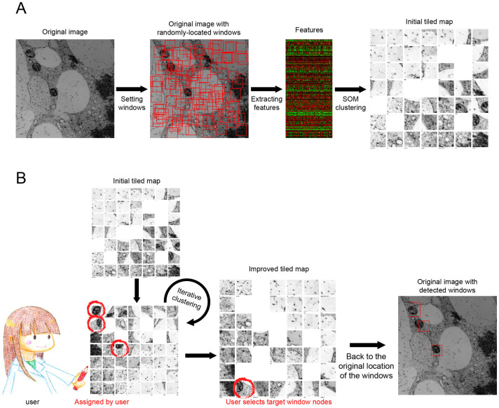
In this study, we analysed TEM images of plant tissues, but similar biomedical images can be efficiently collected by the user-interactive system of CARTA4. Organelles could be detected semi-automatically by analysing a collection of similar subdivided regions of TEM images. First, many square regions of interest, designated as ‘windows' in this study, were placed at random locations covering the entire TEM image (Fig. 1A, Setting windows). The window size can be arbitrarily defined, but we recommend that the size is comparable to that of the target. In all of the examples shown in this report (Fig. 2, 3, 4, 5 and 6), the original TEM image size was 2000 × 2000 pixels, there were 2000 windows, and each window was 50 × 50 pixels. The following procedures to collect similar windows are basically those laid out in the CARTA framework4. An original set of 296 image features (KBI features; http://hasezawa.ib.k.u-tokyo.ac.jp/zp/Kbi/KbiFeatures02)4 was extracted from the windows (Fig. 1A, Extracting features). Then, cluster analyses of the windows in the self-organizing map were performed based on the randomly selected features (Fig. 1A, SOM clustering). The self-organizing map, referred to as the ‘initial tiled map' in this study, serves as the interface for users to manually search for target organelles. The node number of the map can be defined by the user, but 20 × 20 was used in this study (Fig. 2B). The initial tiled map summarizes the distribution of windows based on the features, and shows representative windows at the lattice node (Supplementary Fig. S1). Users can easily find the representative windows containing the targets without laborious visual inspection of the whole image (Fig. 1B, User selects target window nodes). If there is insufficient representation of the target in the windows in the tiled map, the user can improve the map by manually assigning targets (Fig. 1B, Assigned by user). ‘Feature combination' is automatically and optimally selected to improve the clustering results through iterative clustering. In this study, 20 features were selected from the feature set (Supplementary Table S1–5). This process is repeated until the user is satisfied with the map. After interactive assignment and iterative clustering, the user can select the target window nodes in the map, thereby detecting targets in the original TEM image (Fig. 1B, Original image with detected windows).
Figure 1. Workflow of semi-automatic detection of organelles in TEM images.
(A) Scheme of setting randomly located windows and summarizing window distribution based on features. To summarize data from window images in the CARTA framework, a self-organizing map, designated as the initial tiled map, was used4. A part of a tobacco cultured cell TEM image (see also Figure 2) was shown as an example. (B) User interaction to improve the tiled map and detect target organelles. The tiled map can be improved to assemble target organelle windows by repeated manual assignment (handwritten red circles) during iterative clustering. After this improvement, organelles can be semi-automatically detected via the user's selection of representative target window nodes in the map (red rectangles). Stars in the tiled map indicate number of hidden windows at each node (See also Supplementary Fig. S1.).
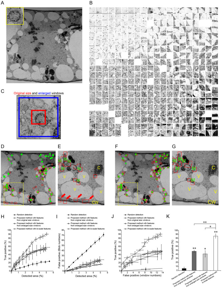
Figure 2. Semi-automatic detection of mitochondria in a tobacco cultured cell TEM image.
(A) TEM image used to detect mitochondria (inset). Image resolution: 2000 × 2000 pixels. (B) Tiled map of 2000 windows, which were randomly located in the TEM image shown in (A). Stars indicate number of hidden windows at each node. (C) Example of original size window (red) and enlarged window (blue). (D) Results of semi-automatic detection based on features from original size windows. Green rectangles show ‘true' mitochondria, which were confirmed by visual inspection; red boxed regions show semi-automatically detected windows. (E) Magnified image of yellow dashed box in (D). M, mitochondrion; C, chromosome; V, vacuole; CW, cell wall. Red arrows show false positive (misdetected) windows. (F) Results of semi-automatic detection based on features from original size and enlarged windows (bi-scale features) as shown in (C). Green rectangles show ‘true' mitochondria; red boxed regions show semi-automatically detected windows that were drawn with original size windows. (G) Magnification of yellow dashed box in (F). M, mitochondrion; C, chromosome; V, vacuole; CW, cell wall. Note the lower rate of misdetection compared with that in (E). (H, I) Relationship between detection area and true (H) or false (I) positive rates of detection with random selection of randomly located windows (filled circles) and with proposed methods with features from original size windows (open squares), enlarged windows (open triangles), and both of them (bi-scale features; open circles). Data are mean ± SD from three independent experiments. (J) Relationship between true and false positive detection rates random selection of randomly located windows (filled circles) and proposed methods based on features from original size windows (open squares), enlarged windows (open triangles), and both of them (bi-scale features; open circles). Data are mean ± SD from three independent experiments. (K) Comparison of true positive detection rates. Mean number of false positive windows was 10.3 (random selection) (N = 4), 12.8 (with features from original size window) (N = 9), 11.3 (with features from enlarged windows) (N = 6) and 12.3 (with bi-scale features) (N = 10). Data are mean ± SD. Significance was determined using Mann–Whitney's U-test (p-value, *<0.0003. **<0.0001).
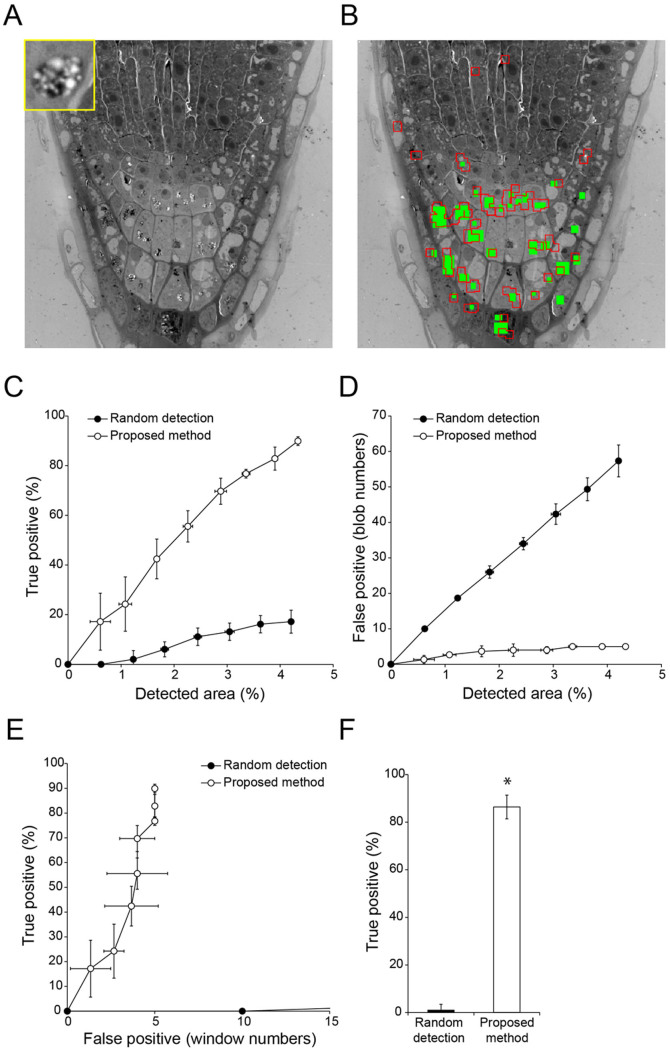
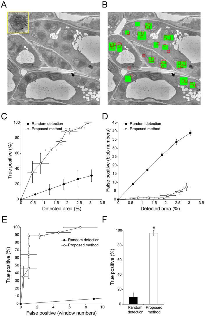
Figure 3. Semi-automatic detection of amyloplasts in a TEM image of Arabidopsis thaliana root tip tissue.
(A) TEM image used to detect amyloplasts (inset). Image resolution: 2000 × 2000 pixels. (B) Result of semi-automatic detection. Green rectangles show ‘true' amyloplasts, which were confirmed by visual inspection; red boxed regions show semi-automatically detected windows. (C, D) Relationship between detection area and true (C) or false (D) positive detection rates with random selection of randomly-located windows (filled circles) and proposed methods (open circles). Data are mean ± SD from three independent experiments. (E) Relationship between true and false positive detection rates with random selection of randomly-located windows (filled circles) and proposed methods (open circles). Data are mean ± SD from three independent experiments. (F) Comparison of true positive detection rates. Mean number of false positive windows was 14.3 (random detection) (N = 6) and 5.00 (proposed method) (N = 6). Data are mean ± SD. Significance was determined using Mann–Whitney's U-test (p-value, *<0.003).
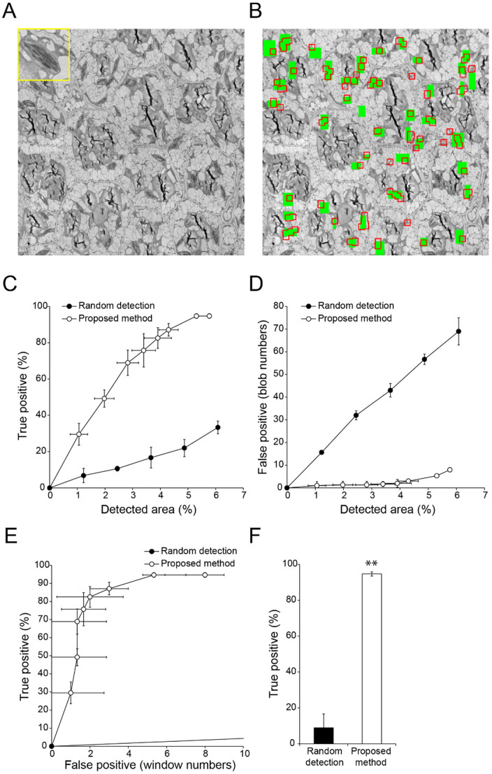
Figure 4. Semi-automatic detection of chloroplasts in a TEM image of Arabidopsis thaliana embryo.
(A) TEM image used to detect chloroplasts (inset). Image resolution: 2000 × 2000 pixels. (B) Results of semi-automatic detection. Green rectangles show ‘true' chloroplasts, which were confirmed by visual inspection; red boxed regions show semi-automatically detected windows. (C, D) Relationship between detection area and true (C) or false (D) positive detection rates with random selection of randomly-located windows (filled circles) and proposed methods (open circles). Data are mean ± SD from three independent experiments. (E) Relationship between true and false positive detection rates with random selection of randomly-located windows (filled circles) and proposed methods (open circles). Data are mean ± SD from three independent experiments. (F) Comparison of true positive rates. Mean number of false positive windows was 33.0 (random detection) (N = 4) and 6.67 (proposed method) (N = 6). Data are mean ± SD. Significance was determined using Mann–Whitney's U-test (p-value, **<0.0001).
Figure 5. Semi-automatic detection of etioplasts in a TEM image of Arabidopsis thaliana cotyledons.
(A) TEM image used for detection of etioplasts (inset). Image resolution: 2000 × 2000 pixels. (B) Results of semi-automatic detection. Green rectangles show ‘true' etioplasts, which were confirmed by visual inspection; red boxed regions show semi-automatically detected windows. (C, D) Relationship between detection area and true (C) or false (D) positive detection rates with random selection of randomly-located windows (filled circles) and proposed methods (open circles). Data are mean ± SD from three independent experiments. (E) Relationship between true and false positive detection rates with random selection of randomly-located windows (filled circles) and proposed methods (open circles). Data are mean ± SD from three independent experiments. (F) Comparison of true positive rates. Mean number of false positive windows was 13.2 (random detection) (N = 6) and 6.00 (proposed method) (N = 6). Data are mean ± SD. Significance was determined using Mann–Whitney's U-test (p-value, *<0.003).
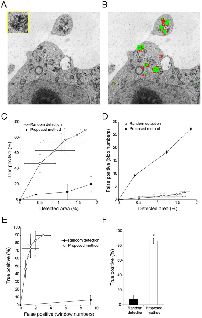
Figure 6. Semi-automatic detection of Golgi stacks and vesicle cluster-shaped compartments (trans-Golgi network and/or secretory vesicle cluster) in a TEM image of tobacco cultured cells.
(A) TEM image used for detection of Golgi stacks and vesicle cluster-shaped compartments2,6 (inset). Image resolution: 2000 × 2000 pixels. (B) Results of semi-automatic detection. Green rectangles show ‘true' Golgi stacks and vesicle cluster-shaped compartments, which were confirmed by visual inspection; red boxed regions show semi-automatically detected windows. (C, D) Relationship between detection area and true (C) or false (D) positive detection rates with random selection of randomly-located windows (filled circles) and proposed methods (open circles). Data are mean ± SD from three independent experiments. (E) Relationship between true and false positive detection rates with random selection of randomly-located windows (filled circles) and proposed methods (open circles). Data are mean ± SD from three independent experiments. (F) Comparison of true positive rates. Mean number of false positive windows was 11.5 (random detection) (N = 4) and 2.50 (proposed method) (N = 6). Data are mean ± SD. Significance was determined using Mann–Whitney's U-test (p-value, *<0.01).
Practical use of proposed method with bi-scale features
To evaluate the accuracy of the method described above, a TEM image of cultured tobacco cells containing 39 ‘true' mitochondria (as confirmed by manual visual inspection) was used as a test case (Fig. 2A). The tiled map was improved via three rounds of manual assignment of mitochondrial windows (Fig. 2B). After the improvement of the tiled map, the mitochondria could be detected in this framework (Fig. 2D, E). The detection rate of true positives increased as the number of selected window nodes increased (Supplementary Video S1). When the detected area reached around 5% of the image area, the detection windows captured approximately 50% of true mitochondria, but approximately 20 windows gave false positive results (misdetection) (Fig. 2D, E, H, I). By comparison, random selection of randomly located windows covered around 20% of mitochondria but more than 60 windows were misdetected when the total detected window area was around 5% of the image (Fig. 2H, I, Supplementary Video S2). These results suggested the method worked to some degree, but that the detection was far from accurate.
In this example, the interface between cytoplasm and cell walls was frequently misdetected as mitochondria (Fig. 2E, arrows). Mitochondria and cell walls are similar in that both have a higher electron density, but their curvature differs on a larger scale. Consequently, we considered that information from enlarged images would improve the accuracy of detection, when combined with information from the original size window (comparable to the size of a mitochondrion). When the KBI features extracted from three-times enlarged windows were combined with those from the original-sized windows (Fig. 2C, Supplementary Table S1) (in total, 592 features; referred to as bi-scale KBI features), the accuracy of detection was dramatically improved (Fig. 2F, G). Using these parameters, approximately 90% of mitochondria were semi-automatically detected, with approximately 10 misdetected windows when the total detected window area was approximately 5% of the total area of the image (Fig. 2H, I). The accuracy was significantly better than that achieved using only 296 KBI features extracted from original-size or enlarged windows (Fig. 2J, K), confirming that the bi-scale KBI features were more useful for organelle recognition in a TEM image.
Performance with various kinds of organelles
To confirm the versatility of the method incorporating bi-scale KBI features, we tried to detect four other kinds of organelles. First, we analysed a TEM image of Arabidopsis thaliana root tip tissue containing amyloplasts, which are organelles for the synthesis and storage of starch granules (Fig. 3A). Manual visual inspection of the image revealed that there were 33 amyloplasts (Fig. 3B, green). Using our proposed method, we successfully detected more than 85% of amyloplasts with approximately 5 misdetected windows when the detected area was approximately 4% of the image area (Fig. 3B, C, D, E, and F). Second, we analysed chloroplasts in a TEM image of an A. thaliana embryo (Fig. 4A). When the proposed method was used to analyse a TEM image containing 44 chloroplasts (Fig. 4B, green), the organelles were detected accurately. When the detected area reached approximately 6% of the image area, more than 90% of chloroplasts were detected with approximately 7 misdetected windows (Fig. 4B, C, D, E, and F). Third, a TEM image of A. thaliana cotyledon tissue containing etioplasts was analysed (Fig. 5A). This image contained 11 etioplasts, which contain a crystalline prolamellar body5 (Fig. 5B, green). Using our method, we detected 90% of etioplasts with 6 misdetected windows when the detected area was approximately 3% of the image area (Fig. 5B, C, D, E, and F). Finally, we analysed Golgi stacks and vesicle cluster-shaped compartments (trans-Golgi network and/or secretory vesicle cluster)2,6 in a TEM image of a cultured tobacco cells (Fig. 6A). When the proposed method was used to analyse a TEM image containing 10 Golgi stacks and the compartments (Fig. 6B, green), they were detected accurately. When the detected area reached approximately 2% of the image area, around 90% of the organelles were detected with approximately 2 misdetected windows (Fig. 6B, C, D, E, and F). Together, these results show that the proposed method is a versatile and highly accurate method to detect organelles in TEM images.
Discussion
Automated detection systems have been proposed as a fundamental technology in computational cell biology7. Many detection methods including thresholding, region-growing, edge-based segmentation, or combinations of these methods have been used as image processing tools. These unsupervised approaches often work well, but require laborious tuning of parameters whenever image properties change as a result of different visualization or capturing methods. Supervised learning approaches have also been used to automatically detect objects. If there is a very large dataset of training images, then this approach can be used relatively easily for accurate detection. For example, supervised learning methods have been used successfully to detect biological objects such as synapses8, platelets9, or rosette-like epithelial tissues10 in fluorescence microscopy images. Such methods have also been used to detect objects in electron microscopic images, including mitochondria11,12 and synapses13. The disadvantages of supervised learning-based approaches are that they generally lack versatility and require a large amount of human labour to produce a large training dataset. Therefore, supervised learning-based detection systems have tended to be disposable systems for specific projects, despite their high costs of development.
Our proposed detection method is based on our original image evaluation framework CARTA, an active learning algorithm developed for high-efficiency data training in machine learning14. The CARTA framework has been used to archive various types of biomedical images such as bright field and fluorescence microscopy images and magnetic resonance images4, demonstrating its versatility. The proposed method takes advantage of the CARTA system for efficient and on-demand organelle detection via a simplified assignment based on a tiled map of representative region windows. Additional customized features can be added easily to the CARTA framework, depending on the purpose of image evaluation4. Interestingly, the detection accuracy was significantly increased by including bi-scale KBI features in the analysis, instead of the simple KBI features (Fig. 2K). These results suggest that including multi-scale features is an attractive strategy to extract features and accurately detect organelles in TEM images, as previously demonstrated for generic object recognition15, medical radiographic image classification16 and analysis of fluorescence microscopy images of cells17. Our proposed method that includes bi-scale KBI features accurately detected mitochondria (Fig. 2), amyloplasts (Fig. 3), chloroplasts (Fig. 4), etioplasts (Fig. 5), and Golgi stacks (Fig. 6), indicating its broad utility to detect biological structures in TEM images. Our proposed method is ready for immediate use to reduce the amount of expert labour required for manual assignment of organelles and for quantitative evaluation of the changes in organelle distribution in large-scale TEM imaging studies2. This method will also be useful to retrieve data on structures of interest from electron microscope image databases18, and to analyse biological structures in innovative three-dimensional electron microscope imaging datasets, such as those that are currently produced in the field of neuroscience1,19.
Methods
Plant materials and TEM imaging
The tobacco (Nicotiana tabacum) BY-2 cell line was prepared by high-pressure freezing/frozen substitution method as described2,6,20. Cotyledons of mature embryo about 10 days after flowering were fixed with 3% glutaraldehyde in a 20 mM sodium cacodylate buffer, pH 7.0, at 4°C overnight, and then postfixed with 1% KMnO4 for 2 hours. Cotyledons of etiolated seedling cultivated for 6 days in the dark were fixed with 2% glutaraldehyde and 4% paraformaldehyde overnight, and then postfixed with 2% OsO4 for 6 hours. These fixed samples were dehydrated in an ethanol series and embedded in Spurr resin. Ultrathin sections (70 nm thick) were stained with uranyl acetate and lead citrate. Observations were made on a JEM-1400 (JEOL, Tokyo, Japan) TEM. Construction of high-resolution TEM pictures was carried out as described2,20.
Image analysis experiments for semiautomatic organelle detection
For preprocessing, the original TEM images were resized to a resolution of 2000 × 2000 pixels with bilinear interpolation using ImageJ software21 to reduce feature measurement times. Then, the images were normalized to an average intensity of 0 with a standard derivation of 1 using KBI plugins (http://hasezawa.ib.k.u-tokyo.ac.jp/zp/Kbi/ImageJKbiPlugins) as previously described22. For image analysis procedures in our proposed method (Figure 1), we used the CARTA ImageJ plugin in KBI version 1192 (freely available at http://hasezawa.ib.k.u-tokyo.ac.jp/zp/Kbi/RegionSearch) with KBI Features version 2, which contains 296 features (http://hasezawa.ib.k.u-tokyo.ac.jp/zp/Kbi/KbiFeatures02)4. To enlarge windows, we used “ImageJ-Edit-Selection-Enlarge…” in the ImageJ menu. In all experiments, we assigned a total of 30 target organelle windows on 20 × 20 nodes of the self-organizing map in the three inspections during iterative clustering (more than 300 clustering trials). Computations were performed on a laptop computer with a Core i5 2.6 GHz processor and 8 GB memory under the Windows 7 operating system (Microsoft, Redmond, WA, USA).
Author Contributions
T.H. designed and performed experiments, analysed data, and wrote the paper. N.K. developed the processing software. K.A. performed experiments and created the illustration of a researcher in Figure 1. M.S., F.S., M.K., N.N. and K.T. contributed TEM images. N.N., K.T. and S.H. coordinated and supervised this project. All authors reviewed the manuscript.
Supplementary Material
Supplementary Information
Organelle detection with proposed method
Random detection
Acknowledgments
We thank Yumi Goto and Mayumi Wakazaki of RIKEN Center for Sustainable Resource Science, for microscopic observations. This work was supported by the Japan Society for the Promotion of Science (JSPS) KAKENHI grant numbers 25711017 to T.H., 24770038 to N.K., 25120727 to N.N., 24687007 to K.T., 23657051 to K.T., 24114007 to S.H., and 24114704 to S.H.
References
- Bock D. D. et al. Network anatomy and in vivo physiology of visual cortical neurons. Nature 471, 177–182 (2011). [DOI] [PMC free article] [PubMed] [Google Scholar]
- Toyooka K. et al. Wide-range high-resolution transmission electron microscopy reveals morphological and distributional changes of endomembrane compartments during log to stationary transition of growth phase in tobacco BY-2 cells. Plant Cell Physiol. 55, 1544–1555 (2014). [DOI] [PubMed] [Google Scholar]
- Baumgartner W. A., Cohen K. B., Fox L. M., Acquaah-Mensah G. & Hunter L. Manual curation is not sufficient for annotation of genomic databases. Bioinformatics 23, 41–48 (2007). [DOI] [PMC free article] [PubMed] [Google Scholar]
- Kutsuna N. et al. Active learning framework with iterative clustering for bioimage classification. Nat. Commun. 3, 1032 (2012). [DOI] [PMC free article] [PubMed] [Google Scholar]
- Nagata N., Suzuki M., Yoshida S. & Muranaka T. Mevalonic acid partially restores chloroplast and etioplast development in Arabidopsis lacking the non-mevalonate pathway. Planta 216, 345–350 (2002). [DOI] [PubMed] [Google Scholar]
- Toyooka K. et al. A Mobile secretory vesicle cluster involved in mass transport from the Golgi to the plant cell exterior. Plant Cell 21, 1212–1229 (2009). [DOI] [PMC free article] [PubMed] [Google Scholar]
- Sommer C. & Gerlich D. W. Machine learning in cell biology–teaching computers to recognize phenotypes. J. Cell Sci. 126, 5529–5539 (2013). [DOI] [PubMed] [Google Scholar]
- Herold J. et al. Flexible synapse detection in fluorescence micrographs by modeling human expert grading. Biomedical Imaging: From Nano to Macro 1347–1350 (5th IEEE International Symposium on Biomedical Imaging, Paris, 2008). [Google Scholar]
- Burduk R. & Krawczyk B. Automatic detection and counting of platelets in microscopic image. J. Med. Inform. Tech. 16, 173–178 (2010). [Google Scholar]
- Lienkamp S. S. et al. Vertebrate kidney tubules elongate using a planar cell polarity-dependent, rosette-based mechanism of convergent extension. Nat. Genet. 44, 1382–1387 (2012). [DOI] [PMC free article] [PubMed] [Google Scholar]
- Cheng L., Ye N., Yu W. & Cheah A. Discriminative segmentation of microscopic cellular images. Medical Image Computing and Computer-Assisted Intervention– Lecture Notes in Computer Science Fichtinger, G., Martel, A. & Peters, T. (eds.) 637–644 (Springer, New York, 2011). [DOI] [PubMed] [Google Scholar]
- Lucchi A., Li Y. & Fua P. Learning for structured prediction using approximate subgradient descent with working sets. Computer Vision and Pattern Recognition 1987–1994 (IEEE Conference on Computer Vision and Pattern Recognition, Champaign, 2013). [Google Scholar]
- Navlakha S., Suhan J., Barth A. L. & Bar-Joseph Z. A high-throughput framework to detect synapses in electron microscopy images. Bioinformatics 29, i9–i17 (2013). [DOI] [PMC free article] [PubMed] [Google Scholar]
- Settles B. [Active learning literature survey]. Computer Science Tech. Rep. 1648 (University of Wisconsin, Madison, 2009). [Google Scholar]
- Maree R., Geurts P., Piater J. & Wehenkel L. Random subwindows for robust image classification. Computer Vision and Pattern Recognition 34–40 (IEEE Computer Society Conference, Washington, 2005). [Google Scholar]
- Marée R., Geurts P., Piater J. & Wehenkel L. Biomedical image classification with random subwindows and decision trees. Computer Vision for Biomedical Image Applications 220–229 (Springer, New York, 2005). [Google Scholar]
- Marée R., Geurts P. & Wehenkel L. Random subwindows and extremely randomized trees for image classification in cell biology. BMC Cell Biol. 10, S2 (2007). [DOI] [PMC free article] [PubMed] [Google Scholar]
- Mano S. et al. The Plant Organelles Database 3 (PODB3) update 2014: Integrating electron micrographs and new options for plant organelle research. Plant Cell Physiol. 55, e1 (2014). [DOI] [PubMed] [Google Scholar]
- Helmstaedter M. & Mitra P. P. Computational methods and challenges for large-scale circuit mapping. Curr. Opin. Neurobiol. 22, 162–169 (2012). [DOI] [PMC free article] [PubMed] [Google Scholar]
- Toyooka K., Sato M., Kutsuna N. & Nagata N. Development of high resolution TEM image acquisition system by using high-pressure freezing method. Plant Morphology 26, 3–8 (2014). [Google Scholar]
- Abramoff M. D., Magelhaes P. J. & Ram S. J. Image processing with ImageJ. Biophotonics Int. 11, 36–42 (2004). [Google Scholar]
- Higaki T. et al. Statistical organelle dissection of Arabidopsis guard cells using image database LIPS. Sci. Rep. 2, 405 (2012). [DOI] [PMC free article] [PubMed] [Google Scholar]
Associated Data
This section collects any data citations, data availability statements, or supplementary materials included in this article.
Supplementary Materials
Supplementary Information
Organelle detection with proposed method
Random detection


