Abstract
We have developed a microfluidic “click chip” incorporating an immobilized Cu(I) catalyst for click reactions. The microfluidic device was fabricated from polydimethylsiloxane (PDMS) bonded to glass and featured ~14,400 posts on the surface to improve catalyst immobilization. This design increased the immobilization efficiency and reduces the reagents’ diffusion time to active catalyst site. The device also incorporates five reservoirs to increase the reaction volume with minimal hydrodynamic pressure drop across the device. A novel water-soluble tris-(benzyltriazolylmethyl)amine (TBTA) derivative capable of stabilizing Cu(I), ligand 2, was synthesized and successfully immobilized on the chip surface. The catalyst immobilized chip surface was characterized by X-ray photoelectron spectroscopy (XPS). The immobilization efficiency was evaluated via radiotracer methods: the immobilized Cu(I) was measured as 1136±272 nmol and the surface immobilized Cu(I) density was 81±20 nmol cm−2. The active Cu(I)-ligand 2 could be regenerated up to five times without losing any catalyst efficiency. The “click” reaction of Flu568-azide and propargylamine was studied on chip for proof-of-principle. The on-chip reaction yields were ca. 82% with a 50 min reaction time or ca. 55% with a 15 min period at 37 °C, which was higher than those obtained in the conventional reaction. The on-chip “click” reaction involving a biomolecule, cyclo(RGDfK) peptide was also studied and demonstrated a conversion yield of ca. 98%. These encouraging results show promise on the application of the Cu(I) catalyst immobilized “click chip” for the development of biomolecule based imaging agents.
Introduction
The use of biomolecules such as peptides or antibodies as the targeting moiety for imaging agents has benefited from the development of “click chemistry” based reactions. A major benefit of “click” reactions is the reduction in the number of protection de-protection steps due to the bioorthogonal nature of these reactions, the functional groups of neither the reactants nor the product interact with the functionalized biomolecule1, and only complementary functional groups form bonds. An additional advantage is that most “click” reactions are compatible with mild non-toxic aqueous conditions, a necessary feature for reactions involving biomolecules. A review on the application of “click chemistry” and bioorthogonal reactions, in labeling biological molecules was published by Best in 2009.2
One of the most common “click” reactions is the Cu(I) catalyzed Huisgen 1,3-dipolar cycloaddition of an azide and alkyne.3 The Cu(I) state is thermodynamically unstable under normal oxidative conditions, but can be protected by complexation with the tetradentate ligand tris-(benzyltriazolylmethyl)amine (TBTA) from oxidation and disproportion.4,5 For in vivo use, imaging agents prepared through “click chemistry” utilizing Cu(I) catalysis requires purification in order to remove the toxic copper salts and any associated ligands from the desired product. An additional consideration is that the reducing agents required to maintain the Cu(I) oxidation state may also react with the other reagents (e.g. peptides or antibodies) leading to adverse effects.6
Microfluidic devices, comprising enclosed micro-channels (normally 10–500 µm wide or tall), mixing units, heaters, pumping systems, are able to control and process chemical or biological reactions in a continuous flow manner or batch mode.7–11 Microreactor synthesis offers: (1) the ability to manipulate small volumes, which mitigates issues associated with dilution effects; (2) efficient mixing to prevent mass transfer limitations, and (3) the ability for fine level of control over reaction conditions, such as reagent concentrations, and temperature, enabling reliable and reproducible reaction yields. These characteristics of microreactors for chemical processing and synthesis are attractive for in situ “click chemistry”, and have been successfully demonstrated in integrated microfluidics platforms for parallel screening or large-scale screening by Tseng et al.10,12
The previously mentioned undesirable requirements of the Cu(I) catalyzed “click” reaction (need for purification and side reactions of reductants) could be eliminated by the immobilization of an oxidatively robust Cu(I) complex. The catalytic copper center can be reduced to the active Cu(I) in the absence of sensitive biological molecules, and the catalyst can then be easily separated from the products. Many previous Cu(I) immobilization schemes utilize nitrogen or carboxylate containing molecules to chelate the copper catalyst onto resins13,14, polysaccharides15, silica particles16, and other solid supports17. One of the more promising immobilized catalyst systems, now commercially available through Sigma-Aldrich, was developed by Chan, et al., and consisted of TBTA bound to TentaGel resin.14 Cu(I) bound to the TBTA functionalized TentaGel displayed high activity with minimal leaching. Solid supports, including TentaGel, can be adapted for use in microreactors by fabricating packed-bed microreactors and directly injecting the suitable resin into the microreactor. These reactors, however, suffer from issues inherent with packed-bed systems, e.g. high back-pressures, reduced sample volumes, channeling and changes in resin swelling with different solvents.
An alternative approach is to immobilize the Cu(I) catalyst onto the microfluidic device itself. Sui, et al. developed a facile method to functionalize intact PDMS devices using an acidic hydrogen peroxide solution and silanes.18 This method, or similar procedures, have been used to immobilize anti-fouling agents19, proteins20, DNA21, and galactose22 onto PDMS surfaces. However, these functionalized PDMS features are primarily used for biological assays or to prevent analyte loss/microchannel fouling. Here we adapted this immobilization procedure and developed a new TBTA derivative for facile functionalization of Cu(I) to PDMS and glass, materials that are amenable for simple fabrication of microfluidic devices. From an application perspective, the research reported here is unique as the immobilization process was used to functionalize an intact microreactor with a chelated metal catalyst for synthetic applications. To the best of our knowledge there is only one report of immobilizing a metal catalyst to the surfaces of a PDMS-based microreactor, this involved nanoparticles rather than a metal-chelate complex.23 A key component of our research was the development and evaluation of a novel TBTA derivative with improved water solubility and capability to be covalently attached to a silane functionalized microreactor. The immobilization process was characterized by both X-ray photoelectron spectroscopy (XPS) and radiotracer studies. We validated the reactor with “click” reactions involving azides and alkynes, and demonstrated improved reaction yields using the microreactor compared to conventional techniques. To the best of our knowledge, this represents the first report of a microreactor incorporating an immobilized Cu(I) catalyst useful for bioconjugation, and where the fabrication procedure is amenable for development of high-density, integrated microfluidic platforms.
Experimental
General
All solvents and chemical reagents were purchased from Sigma-Aldrich (St. Louis, MO) or Fisher Scientific (Pittsburgh, PA) unless specified. All chemicals were used without further purification. Flu568-azide and Flu568-acetylene were purchased from Click Chemistry Tools (Scottsdale, AZ). De-ionized water (DI-H2O) was produced in-house using a Millipore Milli-Q water system. 64CuCl2 was produced at Washington University in St. Louis School of Medicine, and obtained in a 0.1 M HCl solution. Silicon wafers were purchased from University Wafer (Boston, MA). AP-8000 adhesion promoter and SPR220-7.0 were purchased from MicroChem (Newton, MA), and used for fabricating silicon master templates. Sylgard 184 PDMS was purchased from Dow Corning (Midland, MI). Glass microscope slides were purchased from Fisher Scientific, and used to manufacture PDMS reactors. Microbore PTFE tubing (0.012" ID, 0.030" OD) was purchased from Cole-Parmer (Vernon Hills, IL). Silica TLC plates and C18 TLC silica plates were purchased from Sorbent Technologies (Norcross, GA). 1H NMR and 13C NMR spectrometry was performed on an I400 Varian Inova NMR instrument (Agilent, Palo Alto, CA, 400 MHz for 1H NMR and 100.5 MHz for 13C NMR). MALDI-TOF mass spectrometry was performed on a Voyager-DE STR BioSpectrometry Workstation (Applied Biosystems, San Francisco, CA). High resolution electrospray ionization mass spectrometry was conducted on a Thermo Scientific (San Jose, CA) LTQ Orbitrap Velos mass spectrometer with Xcalibur operating system. Three microliter flow modular pump components (syringe pump, a pump driver circuit, and a power supply) were obtained from Harvard Apparatus (Holliston, MA). A Kapton-insulated thin film heater (2"×2"), Omega CN740 temperature controller and an Omega SA 1-RTD probe were obtained from Omega Engineering (Stamford, CT). The ThermoMixer C was purchased from Eppendorf North America (Hauppauge, NY). Microliter syringes were obtained from Hamilton Co. (Reno, NV). The Capintec CRC-712M radioisotope dose calibrator was purchased from Capintec Inc. (Ramsey, NJ), and used for the measurement of radioactivity. X-ray photoelectron spectroscopy was performed on a Kratos Axis Ultra (Kratos Analytical, Manchester, UK). Scanning electron microscope (SEM) imaging was performed on a Hitachi S-4700 SEM (Hitachi Ltd., Tokyo, Japan) with an acceleration voltage of 2 kV. Surface profilometry was measured on an Alpha Step IQ profilometer (KLA-Tencor, Milpitas, CA). Analytical reverse phase high performance liquid chromatography (HPLC) was performed on a Hewlett Packard 1050 series (Model 35900E), and analyzed with Chem Station IC software (Agilent Technologies, Santa Clara, CA). The HPLC analytical column is an Econosil C18 reverse phase column (10 µm, 250 mm) from Alltech Associates, Inc. (Deerfield, IL). The flow rate was 1 mL/min for analytical HPLC and 2.5 mL/min for semi-preparative HPLC, with the mobile phase of solvent A (0.1% TFA in water) and solvent B (0.1% TFA in acetonitrile). The UV detector was set at 576 nm. The gradient analytical HPLC method started at 25% B (0–5 min) and rose to 60% B (10–16 min), and returned to 25% B (16.5–20 min).
PDMS-glass chip fabrication
Lithography
Silicon wafers were rinsed, dried with filtered nitrogen, heated on a hot plate, and then cooled with filtered nitrogen. An adhesion promoter (AP-8000) was dispensed onto the wafers and spin-coated in three consecutive steps: 500 rpm for 2 sec, 1500 rpm for 2 sec, and 3000 rpm for 30 sec. Then SPR220-7.0 (5 mL) was dispensed onto the wafers and spin-coated in two consecutive steps: 500 rpm for 10 sec and 2000 rpm for 30 sec. The photoresist was soft baked on a hotplate for 30 sec at 65 °C, 110 °C for 3 min, then 65 °C for 30 sec, and finally cooled to room temperature for 3 min. The photoresist was exposed to UV light with an intensity of ~14 mW cm−2 through a transparency mask (FineLine Imaging, Colorado Springs, Colorado) and a quartz block for 15 sec followed by a 1 min waiting period. The exposure process was repeated twice for a total exposure time of 45 sec. Exposed photoresist was removed by vigorously swirling wafers in a 4:1 solution of DI water: AZ400K developer for 1 to 3 min. Wafers were rinsed with DI water and dried with filtered nitrogen. The photoresist was then hard baked on a hot plate for 30 sec at 65 °C, 3 min at 110 °C, and 30 sec at 65 °C or 3 min at 80 °C, to make the photoresist more resilient to etching.
Etching
Wafers were briefly cleaned with oxygen plasma, and etched using a Bosch process with a PlasmaTherm ICP-DRIE. After etching, the wafers were swirled for 10 min in 1165 PR stripper, then rinsed with acetone and isopropanol, and finally dried with filtered nitrogen. A PTFE passivation layer was deposited to prevent PDMS from adhering to the silicon.
PDMS attachment to glass
Sylgard 184 reagent was combined in a 10:1 mass ratio (base: curing agent), mixed thoroughly, and degassed in a vacuum desiccator for ~20 min. The PDMS was poured into a petri dish containing the etched master, and cured in an oven at 65 °C for ~2 h. The PDMS was peeled from the master, and the holes for inlets and outlets were punched using 19 gauge hypodermic tubing with beveled edges. Glass slides were scrubbed with a Texwipe soaked in an Alconox solution, and rinsed with E-Pure water (18.0 MΩ cm), then dried with filtered nitrogen. The PDMS and glass were then exposed to oxygen plasma generated by an Atomflo atmospheric plasma system (Surfx Technologies, Redondo Beach, CA) with power set at 100 W, helium flow at 15.0 L min−1 and oxygen flow at 0.30 L min−1. PDMS and glass were slowly passed ~4 times under the plasma, while the oxygen plasma exited a nozzle which was held ~2 cm above the surfaces. The PDMS was immediately sealed to the glass and incubated in an oven at 65 °C overnight.
An illustration of the fabrication process is provided in the supplementary materials (Figure S9).
Profilometer height measurement
After etching the silicon wafers and depositing a PTFE passivation layer the etch heights were measured with a profilometer on the top of a vibration free table. Measurements were made over 13 different sections of the masters. Heights are expressed as the average ± standard deviation.
Synthesis of water-soluble TBTA catalyst
8-Azido-3,6-dioxaoctanol
8-Chloro-3,6-dioxaoctanol (5 g, 28.5 mmol) was dissolved in DI-water (25 mL). Sodium azide (2.4 g, 36.9 mmol) was added to the reaction solution in three portions with caution. The reaction solution was refluxed at 105 °C for 48 h. After the reaction solution cooled down to room temperature, the solvent was removed under vacuum. The residue was washed with acetone (150 mL) to remove any solid salt. The liquid layer was dried over anhydrous sodium sulfate, and then concentrated. The product was further dried under vacuum overnight to afford a viscous yellow liquid (5 g, 96%). 1H NMR (400 MHz, CDCl3): δ 3.67-3.62 (m, 8H), 3.55 (t, J=4.4 Hz, 2H), 3.34 (t, J=4.4 Hz, 2H), 2.77 (br, 1H). 13C NMR (100.5 MHz, CDCl3): δ 72.36, 70.41, 70.14, 69.82, 61.46, 50.41.
Intermediate 1
Tripropargylamine (0.96 g, 7.34 mmol) and tetrakis(acetonitrile)copper(I) hexafluorophosphate (136.8 mg, 0.37 mmol) were dissolved in tetrahydrofuran (10 mL) in a 200 mL round-bottom flask under nitrogen atmosphere. 11-Azido-3,6,9-trioxaundecan-1-amine (0.4 g, 1.83 mmol) was dissolved in tetrahydrofuran (20 mL) and the solution was added to the reaction solution dropwise over 30 min at 40 °C. Then the reaction solution was refluxed at 66 °C for 18 h. After the reaction, the solution was cooled to room temperature. The product was purified by chromatography on silica column with the elution of methanol/dichloromethane 5:95, and then triethylamine/methanol/dichloromethane 2:10:88. The product was obtained as a yellow viscous liquid (0.19 g, 29.7%). 1H NMR (400 MHz, CDCl3): δ 7.74 (s, 1H), 4.85 (br, 2H), 4.54 (t, J=5.0 Hz, 2H), 3.85 (t, J=5.0 Hz, 2H), 3.79 (s, 2H), 3.67 (t, J=4.8 Hz, 2H), 3.60-3.54 (m, 8H), 3.41 (d, J=2.4 Hz, 4H), 3.09-3.00 (m, 4H), 2.29 (t, J=2.2 Hz, 2H). 13C NMR (100.5 MHz, CDCl3): δ 143.64, 124.25, 78.21, 73.67, 70.06, 70.01, 69.91, 69.79, 69.26, 66.38, 50.00, 47.61, 45.70, 41.63. MALDI-TOF: calcd for C17H27N5O3 [M]+: 349.21; found: 349.26. HRMS (ESI): calcd for C17H28N5O3[M+H]+: 350.2187; found: 350.2186.
Water-soluble TBTA 2
Intermediate 1 (0.19 g, 0.54 mmol), 8-azido-3,6-dioxaoctanol (0.23 g, 1.31 mmol) and tetrakis(acetonitrile)copper(I) hexafluorophosphate (81 mg, 0.22 mmol) were dissolved in tetrahydrofuran (5 mL) and refluxed at 66 °C under nitrogen flow. After 18 h, the reaction solution was cooled down to room temperature. The solution was mixed with QuadraPure™ TU resin (0.3 g) in a 50 mL round-bottom flask for 3 h. The solution was filtered, and the crude product was concentrated and purified by chromatography on a silica column using a gradient elution solvent system (methanol/dichloromethane 5:95 to triethylamine/methanol/dichloromethane 2:20:78). The product was afforded as a yellow viscous liquid (0.12 g, 31.6%). 1H NMR (400 MHz, CDCl3): δ 8.06 (s, 2H), 8.04 (s, 1H), 4.60-4.58 (m, 6H), 3.92-3.90 (m, 6H), 3.75 (s, 6H), 3.63-3.56 (m, 20H), 3.51-3.49 (m, 6H), 3.20-3.12 (m, 2H). 13C NMR (100.5 MHz, CDCl3): δ 143.52, 124.86, 72.10, 69.87, 69.84, 69.67, 68.84, 66.37, 60.63, 49.84, 47.50, 46.86, 46.22. MALDI-TOF: calcd for C29H53N11O9 [M]+: 699.40; found: 699.26. HRMS (ESI): calcd for C29H54N11O9[M+H]+: 700.4100; found: 700.4099; calcd for C29H55N11O9[M+2H]2+: 350.7087; found: 350.7086.
Procedures and evaluation for TBTA ligand immobilization on chip
Ligand immobilization
The PDMS-glass chip was activated with a hydrogen peroxide and hydrochloric acid solution (H2O2/HCl/H2O 1:1:5, 4 mL) with flow rate 50 µL min−1. Then the chip was washed with DI-H2O (1 mL), and dried with air for 4 min. A neat solution of 3-(trimethoxylsilyl)propyl acrylate (TMSPA) was pumped into the activated microreactor at 50 µL min−1 for 20 min, then dried with air flow. The silanized chip was annealed at 70 °C under vacuum for 2 h to cure the surface. Ligand 2 (19.5 mg, 29.8 µmol) was dissolved in a 10 mmol% borax solution (1.5 mL),24 and the solution was sonicated for 20 min. The solution was pumped into the chip at the rate of 10 µL min−1 at 47 °C for 150 min. The immobilized chip was washed with water and methanol (2 mL for each solvent), the chip was then dried with air flow for 10 min.
XPS Analysis
XPS experiments were performed using a monochromatic aluminum X-ray source (1486.6 eV). Pass energy was 160 eV for survey spectra and 40 eV for narrow scan spectra. All spectra were collected at a photoelectron take-off angle 90°. To account for sample charging a flood gun was utilized and the hydrocarbon C 1s peak was referenced to 285.0 eV. Analysis was performed utilizing CasaXPS version 2.3.16 software. Shirley background subtraction was used for all analyses.
Quantification of immobilization efficiency
Plastic syringes and Eppendorf tubes were washed with nitric acid (1 N) three times in order to remove any non-specifically bound metals to the chip surfaces. They were then washed with DI water followed by acetone, and dried with air. A Cu-64 stock solution was prepared in sodium acetate buffer (pH 5.5, 0.1 M). Carrier-added Cu(I) solution was prepared by adding 100 mM sodium ascorbate solution into 10 mM radioactive copper sulfate solution with specific activity of ca. 130 Ci/mol. The radiolabeling process was performed at room temperature. The carrier-added radioactive Cu(I) solution (ca. 500 µCi) was pumped into the chip at the rate of 20 µL min−1 for 30 min, then the chip was cleaned with DI-water thoroughly (4 mL), and dried under air flow. All the PTFE tubing was removed, and the radioactivity bound on the chip was counted (120–190 µCi decay corrected). The amount of immobilized Cu(I) on the surface was 1136±272 nmol, and the density of Cu(I) was 81±20 nmol cm−2.
Control study with nonspecific binding of Cu-64
A non-functionalized chip of the same design was cleaned with methanol and water separately at 50 µL min−1 for 10 min. Carrier-added Cu(I) solution was prepared by adding 100 mM sodium ascorbate solution into 10 mM radioactive copper sulfate solution with a specific activity of ca. 110 Ci mol−1. The carrier-added radioactive Cu(I) solution (ca. 500 µCi) was pumped into the chip at the rate of 20 µL min−1 for 30 min, then the chip was cleaned with DI-water thoroughly (4 mL), and dried under air flow. All the PTFE tubing was removed and the chip was counted for radioactivity. The original tubing was then re-inserted into the chip. In order to determine the amount of removable copper bound to the surface, an EDTA (ethylenediaminetetraacetic acid) solution (pH 6, 0.05 M, 1 mL) was pumped into the chip at 30 µL min−1. Then all the tubing was removed and the chip was counted for radioactivity with 7–10 µCi (decay corrected). The remaining amount of copper adsorbed on the surface was 6±1 nmol cm-2.
General procedures for conventional and on-chip click reaction
On-chip “click” reactions
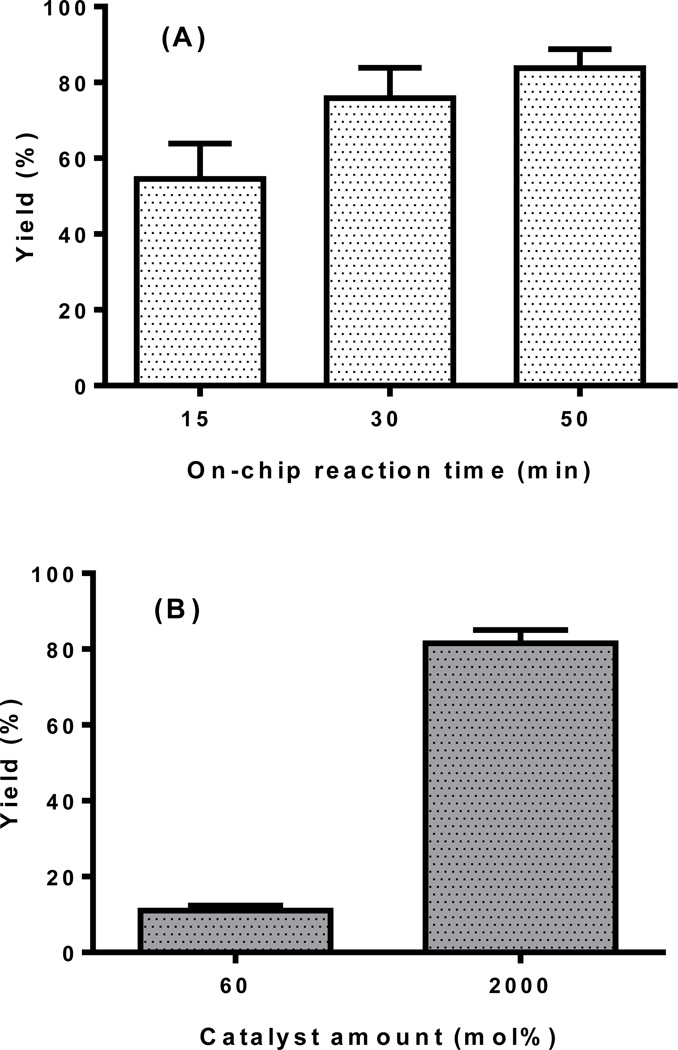
100 µM stock solutions of Flu568-azide and Flu568-acetylene were prepared in an ammonium acetate buffer (pH 6.8, 0.1 M) with 1% sodium dodecyl sulfate (SDS) to increase the solubility. The solution was sonicated for 10 min. Propargylamine stock solution was prepared as 400 µM in an ammonium acetate buffer. The synthesis of cyclo(RGDfK)-N3 peptide was reported previously,25 and prepared as a 600 µM solution in an ammonium acetate buffer. The reaction solution consisted of equal volumes of two reagent stock solutions, and was pumped into the chip from one inlet. The second inlet was connected to the buffer syringe filled with ammonium acetate. The water-soluble TBTA functionalized chip was first activated with Cu(I) by pumping a 5 mM Cu(I) solution prepared from 10 mM copper sulfate and 200 mM sodium ascorbate solutions. The chip was washed thoroughly with DI-water (5 mL). Then the reagent solution was pumped through the chip at flow rate of 25 µL min−1. The reactant flow was controlled by microliter flow modular pump system. Reagent solutions were incubated on chip at 37 °C for 15, 30, or 50 min. After the reaction, the product was eluted from the chip by flowing ammonium acetate buffer into the chip. The chip was further washed with buffer (500 µL) to remove any reaction residue. The reaction was repeated for 4–6 times under the same conditions. The active catalyst immobilized on the chip could be repeatedly regenerated with 5 mM Cu(I) solution as described previously. The products were analyzed by reverse-phase high performance liquid chromatography, and characterized by MALDI-TOF mass spectrometry. The “click” products of the reaction of Flu568-azide and propargylamine were determined by HPLC with yields 54±9% (15 min reaction time), 76±8% (30 min) and 82±4% (50 min). MALDI-TOF: calcd for C38H51N7O9S2 [M]+: 813.32, found: 813.02; C38H50N7NaO9S2 [M+Na-H]+: 835.30, found: 834.90. The “click” product of the reaction of Flu568-acetylene and peptide cyclo(RGDfK)-N3 was determined by HPLC with yield 75±3% (30 min). MALDI-TOF: calcd for C65H88N14O17S2 [M]+: 1400.02, found: 1400.79; C65H87N14NaO17S2 [M+Na-H]+: 1422.57, found: 1422.79.
Conventional “click” reactions
A Cu(I)-TBTA stock solution was prepared by mixing copper sulfate (10 mM, 12.5 µL), sodium ascorbate solution (50 mM, 12.5 µL) and tris[(1-benzyl-1H-1,2,3-triazol-4-yl)methyl]amine (20 mM, 16 µL). Flu568-azide (100 µM, 250 µL) and propargylamine (400 µM, 250 µL) or cyclo(RGDfK)-N3(600 µM, 250 µL) were mixed well, and 60 mol% Cu(I)-TBTA catalyst was added to the reaction solution. The solution was shaken and incubated at 37 °C for 15 min (Figure 3B) or 30 min (Figure 5). The product was analyzed by reverse-phase high performance liquid chromatography. The “click” product of the reaction of Flu568-azide and propargylamine was examined by HPLC with yield 12±2%. MALDI-TOF: calcd for C38H51N7O9S2 [M]+: 813.32, found: 813.94; C38H50N7NaO9S2 [M+Na-H]+: 835.30, found: 835.78. The “click” product of the reaction of Flu568-Acetylene and peptide cyclo(RGDfK)-N3 was examined by HPLC with yield 54±5%. MALDI-TOF: calcd for C65H88N14O17S2 [M]+: 1400.59, found: 1400.79; C65H86N14NaO17S2 [M+Na-2H]+: 1421.56, found: 1421.76.
Figure 3.
“Click” reaction of Flu568-azide and propargylamine at 37°C: (A) on-chip reaction for 15, 30 or 50 min; (B) conventional reaction for 15 min (n=3–4).
Figure 5.
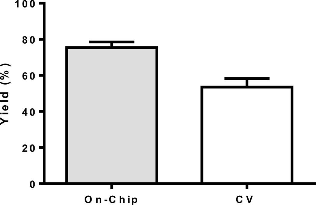
“Click” reaction between Flu568-acetylene and cyclo(RGDfK)-N3 on a functionalized microreactor and conventionally (CV, cat. 60%) for 30 min at 37 °C (n=3–5).
Results and discussion
Microreactor design
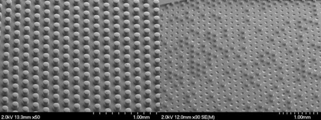
The microreactor was fabricated out of PDMS and glass for the following two reasons: (1) availability of simple, well-established methods for fabrication based on soft lithography, and (2) accessibility of multiple strategies for surface functionalization via creation of reactive silanol groups followed by silane attachment. Sui, et al.’s previous work in particular provided a facile method to form reactive silanol groups in intact PDMS devices for subsequent silanization.18 Deep reactive ion etching (DRIE) was found to produce more robust silicon masters than traditional SU-8 based masters since the DRIE fabricated masters contained a fluorocarbon layer that provided easier liftoff of the PDMS imprints. The resulting PDMS imprints from DRIE fabricated masters displayed no loss of posts after multiple uses of the masters while PDMS imprints made from traditional SU-8 based masters exhibited missing posts with continued use of the masters (Figure 1). When fabricating microreactors with dense features, it may be more efficient to etch silicon using DRIE and then apply a fluorocarbon layer rather than attempt to optimize a process based on traditional SU-8 soft lithography techniques.
Figure 1.
SEM images of PDMS imprints from a DRIE fabricated master (left) and a master created by standard SU-8 soft lithography techniques (right). The images display the equilateral triangle pattern of the posts which ensures rapid diffusion of reagents to catalytic sites (~25 s), and also illustrate the loss of posts when using SU-8 based masters.
Our overall microreactor design included two key features: (1) posts and (2) reservoirs. The posts served primarily to reduce reagent diffusion distances to a catalytic site while also slightly increasing the available surface area for immobilization of the catalyst (~30% increase compared to a device without posts). The 100 µm diameter PDMS posts spaced 100 µm apart minimized the diffusion time of reagents to an active catalytic site to approximately 25 seconds (Formula 1, ≈ (50 µm)2 (10−10 m2 s−1)−1), significantly shorter than the typical overall reaction time (>10 min). Using Formula 1, diffusion times for a device without posts would be roughly 40 seconds with respect to the microreactor bottom and top, but it would take hours to diffuse to the sides of a reservoir. The microreactor contained five reservoirs with an average height of 125.99 ± 1.61 µm (n=13) to provide an adequate sample volume (~46 µL) for analysis. The height and/or number of tanks can be easily increased to provide the desired sample volume with minimal pressure drop compared to scaling up channel-based microreactors. Additionally, if more reservoirs were added to the design the surface area-to-volume ratio is maintained, providing the possibility of increasing sample volume with minimal changes in relative amount of immobilized catalyst.
Formula 1. Approximation of diffusion time (tD is diffusion time, l is characteristic length, and D is the diffusion coefficient).
Ligand Immobilization and evaluation with radioactive 64Cu(I)
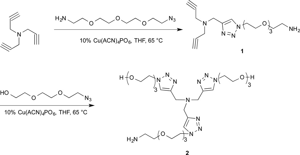
The TBTA-Cu(I) complex has been shown to be an efficient catalyst for “click” reactions.5,14 The Cu(I) state is unstable under normal oxidative conditions, but can be stabilized by complexation with the tetradentate TBTA ligand.4,5 The TBTA ligand has been immobilized on different polymeric materials, e.g. TentaGel14 or polystyrene26, to afford an active Cu(I) catalyst source for “click” reactions. One major issue with the original TBTA developed by Chan et al. from the standpoint of biomolecule compatibility was the limited water solubility. To address this issue we have developed a series of TBTA derivatives (data not shown) and found the water-soluble TBTA derivative ligand 2 as the optimal choice for Cu(I) immobilization. The synthesis of 2 started from a “mono-click” reaction of tripropargylamine and 11-azido-3,6,9-trioxaundecan-1-amine in the presence of the Cu(I) catalyst tetrakis(acetonitrile)copper(I) hexafluorophosphate to afford mono-PEG linker substituted intermediate 1 in 29.7% yield. A second “click” reaction between intermediate 1 and 8-azido-3,6-dioxaoctanol afforded ligand 2 in 31.6% yield (Scheme 1).
Scheme 1.
Synthesis of water-soluble TBTA ligand 2.
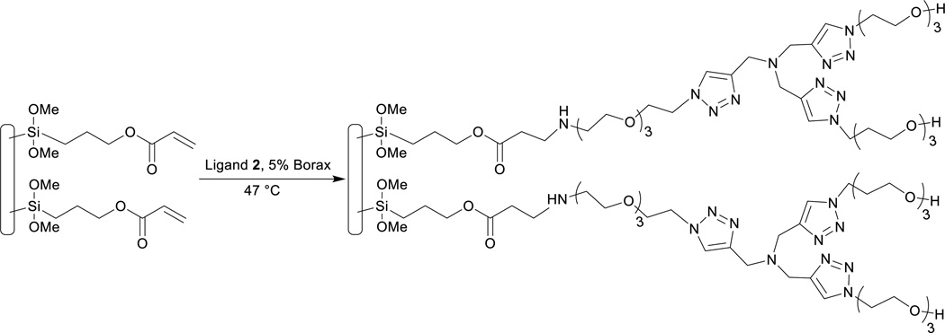
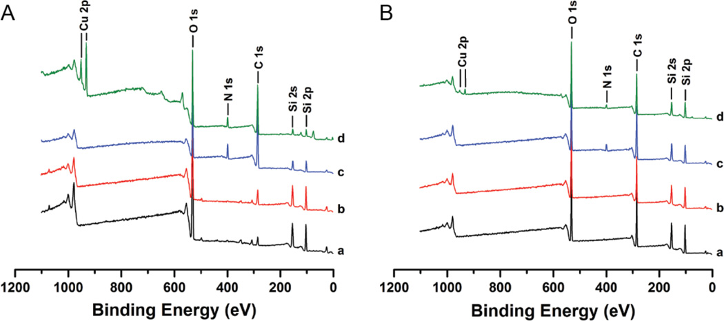
Ligand 2 was successfully immobilized onto the surface of a microchip (Scheme 2). XPS was performed for glass and PDMS substrates which represented each stage of the functionalization process: (1) non-functionalized substrate (control); (2) substrate+TMSPA; (3) substrate+TMSPA+ligand 2; (4) substrate+TMSPA+ligand 2+Cu(I) (Figure 2). A characteristic new peak at ~289 eV in the C 1s narrow scan spectra corresponded well to the O-C=O carbon bond in acrylate molecules. It was detected on both glass and PDMS samples functionalized with TMSPA, which indicated a successful silanization process on the chip (Figures S4, S5). A substantial N 1s peak at ~400 eV in the survey spectra (Figure 2) and an intense C-O peak at ~286 eV in the C 1s narrow scan spectra (Figures S4, S5), were detected on both glass and PDMS samples functionalized with ligand 2. The presence of an N 1s peak indicated the presence of triazole moieties in ligand 2; and the increased intensity and broadness of the C-O peak indicated the presence of ethylene glycol moieties of polyethylene glycol (PEG) chains in ligand 2. All the above observations indicated the water-soluble TBTA derivative was effectively immobilized onto the microreactor surfaces. We also performed a negative control study to prove that the silanization process was essential for ligand 2 immobilization onto PDMS and glass surfaces (Figure S6). No obvious C-O peak associated with the PEG chains in ligand 2 was detected in the C 1s narrow scan spectra for the samples functionalized with ligand 2 without prior functionalization of TMSPA reagent. Therefore, ligand 2 was immobilized onto microreactor internal surfaces via TMSPA spacer and not non-specifically bound to PDMS and glass. Furthermore, the presence of a symmetrical Cu2p3/2 peak and the lack of shake-up peaks in both of the copper narrow scan and XPS survey spectra, indicated the copper oxidation state should be either Cu(0) or Cu(I) instead of Cu(II) (Figure S7).27
Scheme 2.
Immobilization of water-soluble TBTA derivative on chip.
Figure 2.
XPS survey spectra of (A) glass and (B) PDMS samples at each stage of functionalization: (black) non-functionalized substrate; (red) substrate+TMSPA; (blue) substrate+TMSPA+ligand 2; (green) substrate+TMSPA+ligand 2+Cu(I).
Microreactors with ligand 2 attached had a colorless appearance. However, after immobilization of Cu(I), the chip displayed a visibly yellow appearance (Figure S3). The amount of ligand 2 immobilized onto the chip was evaluated via radiotracer methods. Using a known concentration of carrier-added Cu(I) solution containing a trace amount of radioactive Cu-64, we determined the amount of copper bound to the chip by measuring the radioactivity, and thus could calculate the amount of ligand 2 immobilized onto the chip surface assuming the active catalyst was a 1:1 complex of Cu(I) and 2. The chip design incorporating posts was found to have 1136±272 nmol immobilized Cu(I) (n=3), and the surface immobilized Cu(I) density was 81±20 nmol cm−2 (n=3). As our previous studies had shown that copper could be absorbed onto the surface of PDMS based chips,28 a control study was performed to measure the nonspecific binding of Cu(I) onto the PDMS-glass microreactor surface. The various chemical modifications involved with the immobilization of 2 makes it difficult to choose an ideal control model for the surface adsorption of copper. We chose to use a plain chip without any functionalization as the control model. This chip was treated with a radioactive Cu(I) buffer solution using the same procedure described for copper activation of the functionalized chip. Low amounts of Cu-64 (36–48 µCi, decay corrected) were observed on the chip due to nonspecific binding onto the PDMS surface (380±55 nmol). After treatment with an ethylenediaminetetraacetic acid (EDTA) solution (0.05 M, pH 6), only minimal amounts of copper (7–10 µCi, decay corrected) remained on the chip, which corresponded to a copper density of 6±1 nmol cm−2.
“Click” reactions on chip
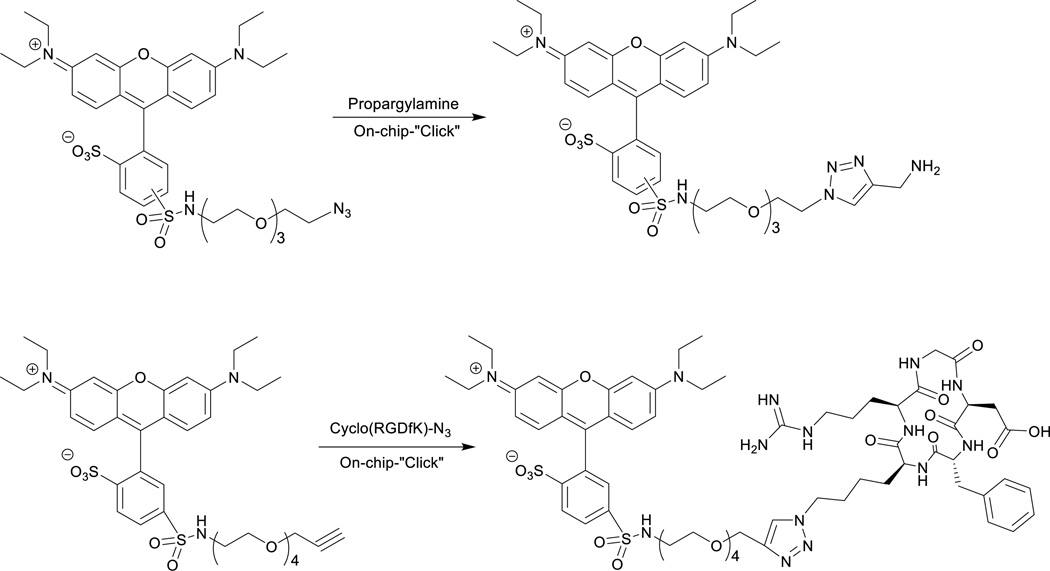
In order to test the utility of the “click chip”, representative test reactions were studied, Scheme 3. The “click” reaction of the Flu568-azide and propargylamine was performed using the activated chip. After the generation of the Cu(I)-ligand 2 on the chip surface, the reaction could be repeated 4–6 times before the yield was observed to decrease significantly. The reaction yield was found to increase with prolonged incubation period. The yield of the above “click” reaction was 55±9% for 15 min reaction, 76±8% for 30 min reaction, and 83±4% for 50 min reaction (Figure 3A). The reactions were then repeated on a different ligand 2 functionalized chip with similar yields (e.g. 52±7% for 15 min reaction). In comparison, the conventional reactions were performed in reaction vials on a ThermoMixer under the same reaction conditions (e.g. reactant concentration, volume, time and temperature). The yield was only 12±2% with 60 mol% Cu(I)-TBTA catalyst for 15 min reaction, which increased to 81±3% in the presence of large excess of catalyst (~2000 mol%). These results clearly indicated that the chip surface was immobilized with sufficient active catalyst to promote the reaction process in a short period of time. The catalysis of this reaction was more efficient on the immobilized chip than that under conventional conditions with a typical catalyst amount (2–15%). The “click” product was collected and examined by high performance liquid chromatography (HPLC) (Figure S1). The product peak was characterized by MALDI-TOF mass spectrometry at 813.02 m/z.
Scheme 3.
On-chip “Click” reactions: (a). Flu568-azide and propargylamine; (b) Flu568-acetylene and cyclo(RGDfK)-N3.
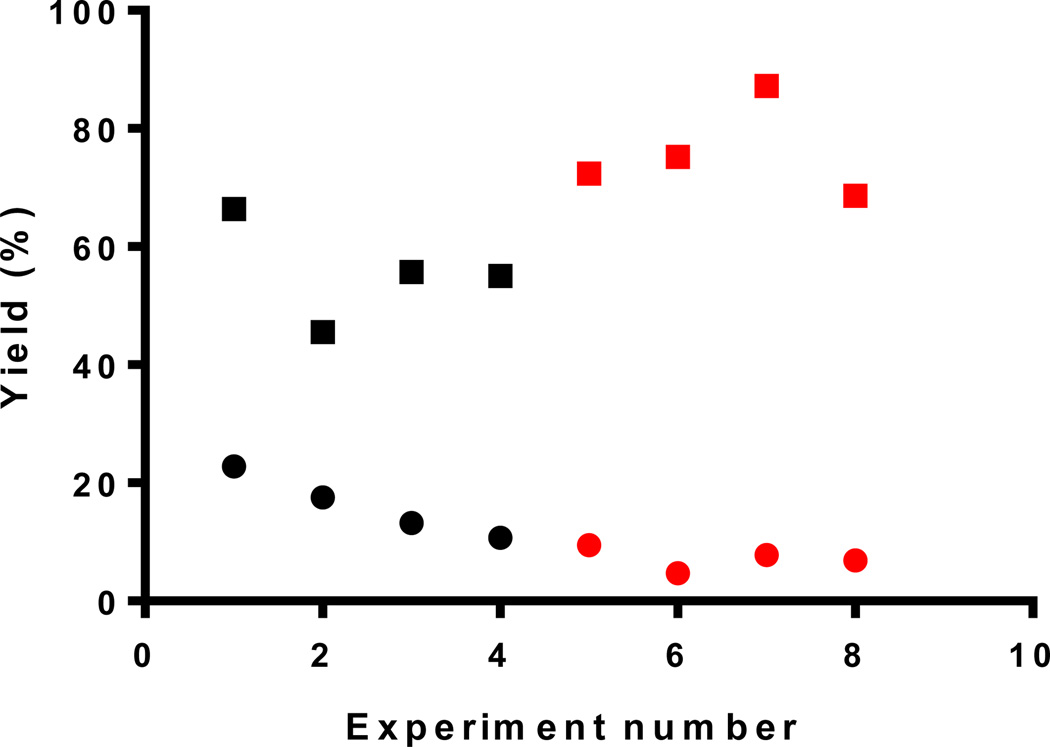
To confirm that the Cu(I)-ligand 2 complex was the active catalyst, the same experiment was performed on a plain chip without any TBTA functionalization. A Cu(I)-ascorbate solution was pumped through the chip, then the chip was washed well with DI-water. The nonspecifically bound Cu(I) catalyzed the reaction (15 min reaction time) but with a significantly lower yield of 16±5%. When the reaction was repeated on the same control chip, the reaction yield decreased dramatically even with increased incubation time, e.g. the yield of 30 min reaction decreased to 7±2% (Figure 4). In comparison, the same series of experiments when performed on a ligand 2 functionalized chip, gave a yield for the 30 min reaction of ~75% identical to the initial 30 min result. These results unambiguously proved that the immobilized Cu(I)-ligand 2 complex was the active catalyst with adsorbed Cu(I) playing only a minor catalytic role, which rapidly diminished over repeated use of the chip.
Figure 4.
“Click” reaction between Flu568-acetylene and propargylamine on a functionalized microreactor (square) and a non-functionalized chip (dot) for 15 min (black) or 30 min (red) at 37 °C.
Studies to determine the robustness of the functionalization on chip confirmed that the functionalized chip remained effective for at least one month allowing for reuse, so long as the Cu(I) catalyst was regenerated as needed. The reactions of Flu568-azide and propargylamine (15 min reaction time) were performed on different days to study the shelf-life of the ligand 2 immobilized chip. It was observed that the reaction yields on days 1, 2, 5, 8, 11 were similar (Figure S8), and the reaction yield on day 11 was consistent with that of day 1 after three regenerations of the Cu(I)-ligand 2 catalyst during this study (55±9% on day 1 v.s. 48±5% on day 11). No visible loss of ligand 2 was observed from the microchip (visual inspection for gaps in the yellow color). The same reaction (30 min reaction time) could be repeated ~20 days later with similar yield (77±6% vs. 76±8%) on the same chip. The reaction yield of the 50 min reaction time remained above 80% after one month of usage of the chip. After five regenerations of the Cu(I)-ligand 2 catalyst, however, the chip was deemed unusable when the reaction yield decreased significantly, and the tank surface became discolored in some spots which indicated that ligand 2 may have detached from the surface.
To validate the application of the reactor for use with biomolecules, we studied the “click” reaction between an azide containing peptide cyclo(RGDfK)-N325 and Flu568-acetylene. The reactions were performed on chip with a 30 min reaction time, and were repeated six times without losing any catalytic efficiency. The reaction yields were determined by HPLC. It was found that the reaction yield (based on loss of the dye) of the Flu568-acetylene was ~98%; however, the product yield of conjugated peptide was only 75±3%, which eluted at 12.5 min on HPLC (Figure S2). The remainder of the Flu568-acetylene was converted into an uncharacterized byproduct which eluted at 13.4 min in the HPLC spectrum. We postulated that this byproduct arose from a reaction between the Flu568-acetylene and the Cu(I) catalyst, and possibly reduced the reaction yield. This same byproduct was also observed in the conventional reaction, with Flu568-acetylene mixed with an excess amount of Cu(I)-ligand 2 in solution at 37 °C. The conventional reaction of cyclo(RGDfK)-N3 and Flu568-acetylene with 60 mole% catalyst afforded only 54±5% product yield (Figure 5). These results confirmed that the RGD peptide was compatible with the catalyst-immobilized chip, and a higher yield could be achieved using the microfluidic platform compared to conventional techniques.
Conclusion
We have developed a new robust catalyst Cu(I)-ligand 2, immobilized on a novel PDMS-glass microchip for performing “click” reactions. The fabricated “click chip” eliminates the need to separate copper species from products, and eliminates side reactions of the copper reductant, typically ascorbate, with sensitive biomolecules. The Cu(I) catalyst was regenerated on chip five times without losing catalytic efficiency. A model reaction, the “click” reaction of Flu568-azide and propargylamine was studied on chip for proof-of-principle. The on-chip reaction yield reached ca. 82% with a 50 min reaction time at 37 °C. A “click” compatible peptide cyclo(RGDfK)-N3 was then tested for reactivity with the dye Flu568-acetylene, and the reaction was found to give a conversion yield of ca. 75%. These results highlight the potential of the “click chip” for the development of biomolecule based imaging agents.
Supplementary Material
Acknowledgements
We acknowledge the financial support of National Institutes of Health (5R01CA16134802) for this research, and the NIH National Cancer Institute Alliance for Nanotechnology in Cancer “Midwest Cancer Nanotechnology Training Center” (R25 CA154015A) for partially funding Mr. Joseph J. Whittenberg. We thank Dr. Fong-Fu Hsu at WUSTL-School of Medicine Biomedical Mass Spectrometry Facility for the assistance of high resolution electrospray ionization mass spectrometry. Experiments were carried out in part in the Frederick Seitz Materials Research Laboratory Central Facilities and Micro-Nano-Mechanical Systems Cleanroom at University of Illinois at Urbana-Champaign. We thank Dr. Rick Haasch at UIUC for his assistance with XPS experiments.
References
- 1.Nwe K, Brechbiel MW. Cancer Biother Radiopharm. 2009;24:289–302. doi: 10.1089/cbr.2008.0626. [DOI] [PMC free article] [PubMed] [Google Scholar]
- 2.Best MD. Biochemistry. 2009;48:6571–6584. doi: 10.1021/bi9007726. [DOI] [PubMed] [Google Scholar]
- 3.Rostovtsev V, Green L, Fokin V, Sharpless K. Angew. Chem. Int. Ed. 2002;41:2596–2599. doi: 10.1002/1521-3773(20020715)41:14<2596::AID-ANIE2596>3.0.CO;2-4. [DOI] [PubMed] [Google Scholar]
- 4.Wang Q, Chan TR, Hilgraf R, Fokin VV, Sharpless KB, Finn MG. J Am Chem Soc. 2003;125:3192–3193. doi: 10.1021/ja021381e. [DOI] [PubMed] [Google Scholar]
- 5.Chan TR, Hilgraf R, Sharpless KB, Fokin VV. Org Lett. 2004;6:2853–2855. doi: 10.1021/ol0493094. [DOI] [PubMed] [Google Scholar]
- 6.Hong V, Presolski SI, Ma C, Finn MG. Angew. Chem. 2009;48:9879–9883. doi: 10.1002/anie.200905087. [DOI] [PMC free article] [PubMed] [Google Scholar]
- 7.Jähnisch K, Hessel V, Löwe H, Baerns M. Angew. Chem. 2004;43:406–446. doi: 10.1002/anie.200300577. [DOI] [PubMed] [Google Scholar]
- 8.Watts P, Haswell SJ. Chemical Society reviews. 2005;34:235–246. doi: 10.1039/b313866f. [DOI] [PubMed] [Google Scholar]
- 9.DeMello AJ. Nature. 2006;442:394–402. doi: 10.1038/nature05062. [DOI] [PubMed] [Google Scholar]
- 10.Lin W-Y, Wang Y, Wang S, Tseng H-R. Nano Today. 2009;4:470–481. doi: 10.1016/j.nantod.2009.10.007. [DOI] [PMC free article] [PubMed] [Google Scholar]
- 11.Longstreet AR, McQuade DT. Acc Chem Res. 2013;46:327–338. doi: 10.1021/ar300144x. [DOI] [PubMed] [Google Scholar]
- 12.Wang Y, Lin W-Y, Liu K, Lin R, Selke M, Kolb H, Zhang N, Zhao X-Z, Phelps M, Shen C, Faull K, Tseng H-R. Lab Chip. 2009;9:2281–2285. doi: 10.1039/b907430a. [DOI] [PMC free article] [PubMed] [Google Scholar]
- 13.Girard C, Onen E, Aufort M, Beauvière S, Samson E, Herscovici J. Org Lett. 2006;8:1689–1692. doi: 10.1021/ol060283l. [DOI] [PubMed] [Google Scholar]
- 14.Chan T, Fokin V. QSAR and Combinatorial Science. 2007;26:1274–1279. [Google Scholar]
- 15.Rajender Reddy K, Rajgopal K, Lakshmi Kantam M. Catal Lett. 2007;114:36–40. [Google Scholar]
- 16.Li P, Wang L, Zhang Y. Tetrahedron. 2008;64:10825–10830. [Google Scholar]
- 17.Dervaux B, Du Prez FE. Chemical Science. 2012;3:959–966. [Google Scholar]
- 18.Sui G, Wang J, Lee C-C, Lu W, Lee SP, Leyton JV, Wu AM, Tseng H-R. Anal Chem. 2006;78:5543–5551. doi: 10.1021/ac060605z. [DOI] [PubMed] [Google Scholar]
- 19.Croushore CA, Supharoek S-A, Lee CY, Jakmunee J, Sweedler JV. Anal Chem. 2012;84:9446–9452. doi: 10.1021/ac302283u. [DOI] [PMC free article] [PubMed] [Google Scholar]
- 20.Deshpande KS, Kuddannaya S, Staginus J, Thüne PC, de Smet LCPM, ter Horst JH, van der Wielen LAM, Ottens M. Biochemical Engineering Journal. 2012;67:111–119. [Google Scholar]
- 21.Liu D, Perdue RK, Sun L, Crooks RM. Langmuir. 2004;20:5905–5910. doi: 10.1021/la049605p. [DOI] [PubMed] [Google Scholar]
- 22.Hsu F-Y, Kuo K-L, Liou H-M. Journal of the Taiwan Institute of Chemical Engineers. 2012;43:165–171. [Google Scholar]
- 23.Lin R, Freemantle RG, Kelly NM, Fielitz TR, Obare SO, Ofoli RY. Nanotechnology. 2010;21:325605. doi: 10.1088/0957-4484/21/32/325605. [DOI] [PubMed] [Google Scholar]
- 24.Hussain S, Bharadwaj S, Chaudhuri M, Kalita H. European Journal of Organic Chemistry. 2007:374–378. [Google Scholar]
- 25.Li H, Zhou H, Krieger S, Parry JJ, Whittenberg JJ, Desai AV, Rogers BE, Kenis PJA, Reichert DE. Bioconjug Chem. 2014;25:761–772. doi: 10.1021/bc500034n. [DOI] [PMC free article] [PubMed] [Google Scholar]
- 26.Lammens M, Skey J, Wallyn S, O’Reilly R, Du Prez F. Chemical Communications. 2009;46:8719. doi: 10.1039/c0cc01451f. [DOI] [PubMed] [Google Scholar]
- 27.Biesinger MC, Lau LWM, Gerson AR, Smart RSC. Applied Surface Science. 2010;257:887–898. [Google Scholar]
- 28.Wheeler TD, Zeng D, Desai AV, Onal B, Reichert DE, Kenis PJA. Lab Chip. 2010;10:3387–3396. doi: 10.1039/c0lc00162g. [DOI] [PubMed] [Google Scholar]
Associated Data
This section collects any data citations, data availability statements, or supplementary materials included in this article.


