Abstract
Purpose:
Several groups are exploring the integration of magnetic resonance (MR) image guidance with radiotherapy to reduce tumor position uncertainty during photon radiotherapy. The therapeutic gain from reducing tumor position uncertainty using intrafraction MR imaging during radiotherapy could be partially offset if the negative effects of magnetic field-induced dose perturbations are not appreciated or accounted for. The authors hypothesize that a more rotationally symmetric modality such as helical tomotherapy will permit a systematic mediation of these dose perturbations. This investigation offers a unique look at the dose perturbations due to homogeneous transverse magnetic field during the delivery of Tomotherapy® Treatment System plans under varying degrees of rotational beamlet symmetry.
Methods:
The authors accurately reproduced treatment plan beamlet and patient configurations using the Monte Carlo code geant4. This code has a thoroughly benchmarked electromagnetic particle transport physics package well-suited for the radiotherapy energy regime. The three approved clinical treatment plans for this study were for a prostate, head and neck, and lung treatment. The dose heterogeneity index metric was used to quantify the effect of the dose perturbations to the target volumes.
Results:
The authors demonstrate the ability to reproduce the clinical dose–volume histograms (DVH) to within 4% dose agreement at each DVH point for the target volumes and most planning structures, and therefore, are able to confidently examine the effects of transverse magnetic fields on the plans. The authors investigated field strengths of 0.35, 0.7, 1, 1.5, and 3 T. Changes to the dose heterogeneity index of 0.1% were seen in the prostate and head and neck case, reflecting negligible dose perturbations to the target volumes, a change from 5.5% to 20.1% was observed with the lung case.
Conclusions:
This study demonstrated that the effect of external magnetic fields can be mitigated by exploiting a more rotationally symmetric treatment modality.
Keywords: MRIgRT, Tomotherapy, Monte Carlo, Radiation therapy
1. INTRODUCTION
Conformal delivery of radiation to moving tumors is an ongoing challenge in radiation therapy. There is recent interest to exploit real-time magnetic resonance imaging (MRI) during treatments to monitor and compensate for intrafractional tumor motion. This interest in magnetic resonance imaging-guided radiation therapy (MRIgRT) has led several groups to develop or propose prototype systems combining linear accelerators (Linac)1–4 or teletherapy-like systems with magnetic resonance (MR) scanners.5,6 ViewRay™ (Oakwood Vollage, OH) has developed a MRI-guided teletherapy unit utilizing cobalt-60 source,5 which is currently being used to treat patients at multiple locations in the U.S. These units offer the benefit of reduced mechanical complexity and magnetic shielding of the source, as well as reduced dose perturbations due to the lower energy of liberated electrons. However, steeper dose falloff at depth, overall lower dose rates, and higher skin dose relative to Linac beams may make these units less desirable clinically. Several combined MRI and Linac systems are currently under development or are in the planning stage. These systems will utilize nonconventional magnetic field arrangements and shielding to avoid magnetic field infringement on the electron acceleration process. These systems will likely be treating patients within the next few years.
One unavoidable consequence of MR imaging during radiotherapy is the influence of the magnetic field on dose distributions inside the patient. Despite being inconsequential to the primary photon beam, the Lorentz force will deflect secondary charged particles in a helical motion around magnetic field lines. Neglecting the influence of magnetic fields on dose distributions during planning and delivery could jeopardize treatment outcome and the safety of the patient. In general, physical constraints limit magnetic field arrangements in MR-guided treatment modalities to two basic configurations, longitudinal and transverse, as defined by the direction of the magnetic field relative to that of the incident photon beam.7 The dose perturbations due to both magnetic field configurations have been well documented in simple slab geometries and fixed-angle IMRT scenarios.7–12 Generally, the transverse magnetic field configuration, one where the magnetic field is perpendicular to the direction of the radiation beam, results in the electron return effect (ERE) which at high-to-low density interfaces, causes a lateral shift of the dose penumbra relative to the beam penumbra at depth, an asymmetric over- and underdosing in cavities, and an increased buildup region at low-to-high density interfaces. In contrast, the parallel configuration reduces these dosimetric perturbations, such as no lateral dose shifting, a reduction in penumbra widths, no electron return effect, and a reduced secondary buildup region at lung–tissue interfaces. However, parallel configurations can give rise to hot spots of excessive skin dose that can range up to 1000% of Dmax. These effects not only vary due to the magnetic field strength and orientation but also the electron kinetic energy, as the dose perturbations are a combination of the electron path-length in a given medium as well as the electron gyro radius. Our work focuses on the dosimetric perturbations impacting rotational deliveries by MV-energy Linacs in the transverse field configuration.
Along with others, our group has demonstrated that transverse magnetic fields have a strong influence on dose distributions in simple slab phantoms.8,9 For single beams, a transverse magnetic field can decrease the buildup region, create an asymmetric dose profile, and may cause additional dose gradients at tissue interfaces that would not have been there in the absence of the MR field. These dose gradients are due to the ERE where electrons entering a low-density cavity are deflected by the magnetic field back into the originating tissue ultimately creating charged particle disequilibrium. Furthermore, other groups have demonstrated similar effects in patient geometries during radiation therapy treatments.3,7,13 As with single treatment fields, the dose perturbations in multifield radiation therapy treatments due to perpendicular magnetic fields were characterized by edges of under- and overdosing along the beam penumbra, as well as in high and low-density tissue interfaces, including increased exit dose due to ERE electrons. In the case of both conventional and step-and-shoot IMRT plans, it is evident that limiting beam angles to mitigate the ERE inside and surrounding the tumor degrades the treatment plan quality. For example, the use of opposing fields to minimize the effect of overdosing and underdosing along the beam penumbra7,13 may also constrain the degrees of freedom of the radiation therapy plan. In addition, static treatment fields have resulted in elevated surface doses due to the ERE effect, with hot spots reaching up to 50% of the prescribed dose,11 an undesirable effect could lead to acute skin complications.
All of the previously referenced clinical cases only considered fixed-field IMRT treatment deliveries.3,7,13 In contrast, a more rotationally symmetric modality, such as helical tomotherapy (HT) or volumetric arc therapy, should permit a natural systematic mediation of these dose perturbations. The circumferential delivery in tomotherapy creates an angular averaging of magnetic field-induced perturbations. As aresult, certain magnetic field-induced perturbations, such asthe increase in exit dose due to return electrons, are spread over through an effectively infinite number of “beamlets,” rather than in discrete beam positions such as in fixed-field IMRT, and the rotational nature of the delivery also allows for more natural cancelation of any dose perturbations along the beamlet penumbra, similar to when using opposed beamlets. Any ERE effect on the exit dose is also more uniformly distributed leading to reduced hot spots in the skin. To the best of our knowledge, we are the first to present a Monte Carlo (MC) investigation on the dose perturbations created from introducing a homogeneous magnetic field during these rotational-type treatments.
A hypothetical MR-guided helical tomotherapy modality was used for this investigation, the rationale being that: (1) similarities between HT and arc-based therapies suchas volumetric modulated arc therapy (VMAT) in comparison with IMRT have been well documented, most notably the higher degree of conformity achieved by HT and VMAT and better organ at risk (OAR) sparing relative to IMRT,at the cost of higher integral dose,14–16 (2) the theoretical proposals of both a MR-guided HT system5 as well as aMR-guided volumetric arc therapy17 motivate additional investigation into this delivery modality, (3) our access to a preexisting detailed and accurate Tomotherapy® head model19–21 and patient cases allows us to assess any potential clinically relevant consequences due to magnetic field-induced dose perturbations.
2. METHODS
For this study, the well-known Monte Carlo code geant4 version 9.5 (Ref. 18) was used to simulate the dose distributions for three clinical Tomotherapy® patient cases planned using the clinical Tomotherapyy® treatment planning system (TPS), subjected to a constant transverse uniform magnetic field. The three patient cases included a head and neck (HN) case, a lung case, and a prostate case. The transverse magnetic field was applied to the simulated geometry, at field strengths of B = 0, 0.35, 0.7, 1.5, and 3 T. The field is oriented parallel to the patient’s long axis and perpendicular to the incident beam axes and axial CT slices. The field is assumed to be uniform throughout the entire geometry, but assumed to have no impact on the incident photon fluence. Sections 2.A–2.C provide details pertaining to the simulations including descriptions of the geometries, source parameters, and physical parameters.
2.A. Simulation details
For this work, previously recorded phase space distributions were recycled for each treatment plan derived from the well-benchmarked code TomoPen.20 The TomoPen MC framework has been previously described in detail.19,20 Briefly, TomoPen includes a detailed model, the Tomotherapy® system, and relies on a fast technique for transporting beamlets through the binary collimator called the transfer functionmethod.21 TomoPen can simulate either 51 projections/rotation or a virtually helical motion by dividing each projection into an arbitrary number of subprojections.20 The source model consisted of a phase space file calculated by transporting a 5.5 MeV electron beam with a spatial Gaussian distribution of FWHM = 1.4 mm through a detailed Tomotherapy® head model. The source model agrees with measured transverse and depth-dose profiles to within 2%.21 For our work, details of the Tomotherapy® treatment plan were transferred to the TomoPen framework and phase space distributions were recorded. Phase space distributions along with CT data were then imported into our geant4 framework for dose simulations in patient tissues involving magnetic fields. As the transfer function method does not transport electrons, contaminant electrons from the head of the tomotherapy machine are not included.
Patient geometry was defined with three general material compositions of water, compact bone, and air taken from ICRU Report 44.22 A bilinear conversion of Hounsfield units (HU) to material density was done using a standard HU to density calibration curve. Voxels with density below 0.2 g/cm3 were mapped to air, density between 0.2 g/cm3 and 1.1 g/cm3 to tissue, and the remainder to bone. Following the simulations, the planning structures were exported and used for generating dose–volume histogram (DVH) metrics from the MC dose distributions. Patient geometries were comprised of voxels with size 1.875 × 1.875 × 3 mm3, 1.95 × 1.95 × 2.5 mm3, and 1.95 × 1.95 × 2 mm3 for the prostate, head and neck, and lung cases, respectively.
2.B. Physical parameter settings
The standard CLHEP package was used in the geant4 simulations. Photon and electron interactions were handled with the Livermore Low Energy Physics cross section data. It has been shown that this is the most accurate cross section dataset for low energy (∼250 eV) photon and electron interactions.8 Magnetic fields were set in the geant4 geometry by invoking the G4UniformMagField class. The trajectory of a charged particle in a constant magnetic field is calculated by an analytical solution to the ordinary differential equation associated with its motion. The default values for transport parameters were used in all simulations, except for the step-size, which was limited to 0.1 mm in order to accurately account for combined effect of multiple Coulomb scattering and magnetic field deflection of charged particles.
2.C. Clinical plans
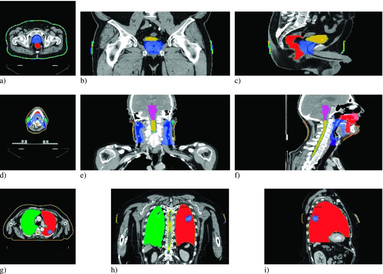
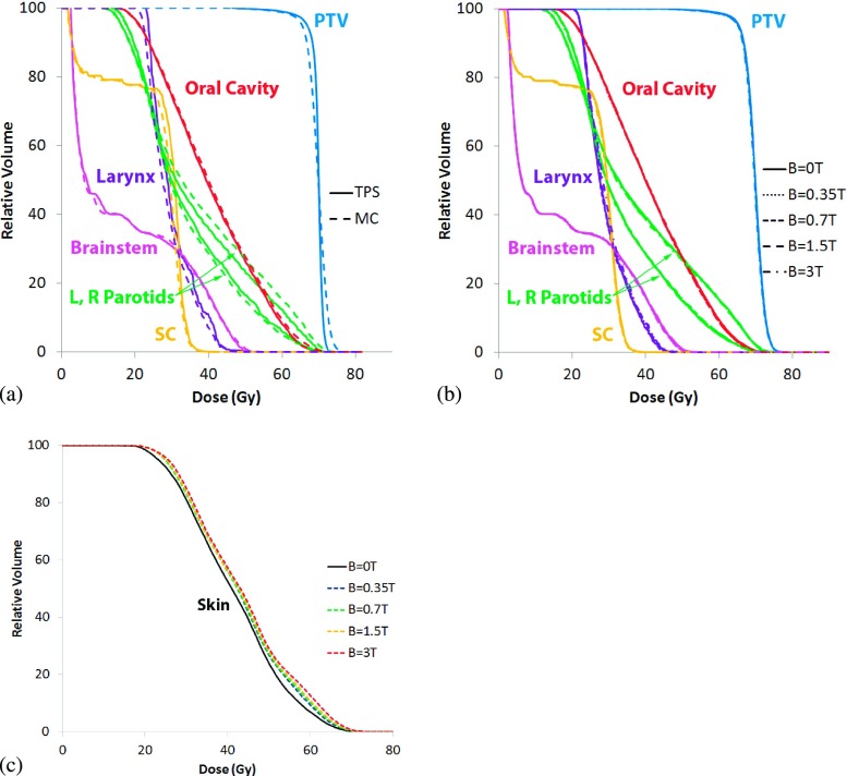
The three Tomotherapy® plans chosen for this investigation were a prostate, head-and-neck, and lung case. The plans were generated on Version 5.0 of the TomoTherapy Plan- ning Station, using the nonvoxel broad beam collapsed cone convolution/superposition (NVBB CCCS) algorithm.23 The prostate case demonstrates a classic example of a well-defined target within a relatively homogeneous geometry. The plan utilized a dynamic jaw treatment with a maximum field width of 2.5 cm to deliver a planning target volume (PTV) median dose of 70 Gy in 35 fractions. For the prostate, the PTV, and two OARs, the rectum and bladder (Fig. 1) were used to compare the results of the Monte Carlo simulations to the treatment planning DVHs. The HN case was chosen to represent a highly complex PTV and OAR geometry. The plan utilized a dynamic jaw24 treatment with a maximum field width of 2.5 cm to deliver a PTV median dose of 70 Gy in 30 fractions. The DVHs of the high risk PTV and the five highest-weighted OARs were used to compare the results of the Monte Carlo simulations to the treatment planning DVHs. These structures included the oral cavity, larynx, brainstem, left and right parotids, and the spinal cord (Fig. 1). In the simulations, 6.1 × 10⁸ histories were used to simulate the prostate case, 4.8 × 10⁸ for the HN case, and 1.6 × 10⁸ for the lung.
FIG. 1.
PTV and avoidance structures for the prostate (a), (b), and (c), head and neck (d), (e), and (f), and lung (g), (h), and (i) patient plans, in the transverse (a), (d), and (g), coronal (b), (e), and (h), and sagittal (c), (f), and (i) views.
The lung case is arguably the most important treatment scenario for MRIgRT, as periodic motion of the lung and target within a large low-density region can be more precisely and directly tracked with MR image guidance, but it involves the worst dosimetric configuration with low density that enhances the range of the spiraling charged particles. The PTV was a well-defined target in the left lung; the three organs at risk used in the comparison include the spinal cord, right, and left lung (Fig. 1). The plan utilized a dynamic jaw treatment with a field size of 2.5 cm to deliver a PTV median dose of 60 Gy in 16 fractions. The DVHs of the PTV, and three organs at risk, were used to compare the results of the Monte Carlo simulations to the treatment planning system.
In addition to the original planning structures used to optimize the treatments, skin contours were created for all three cases to evaluate skin dose perturbations due to the magnetic fields. The structures encompass the outermost 3 mm of the patient geometry, and only for axial slices that also contained the PTV, which helped to isolate changes to skin dose due to ERE electrons.
2.D. Dose heterogeneity index (DHI)
The helical trajectories of liberated charged particles created by the transverse magnetic field could lead to dose heterogeneities in the target volumes defined above. In order to quantitatively assess this impact, we used the following definition of the DHI:
| (1) |
where D20 and D80 represent the minimum dose to 20% and 80% of the target volume and Dpres is the prescribed dose. Therefore, a larger DHI value corresponds to a more heterogeneous dose in the target volume.
3. RESULTS
All of the Monte Carlo simulation results showed excellent agreement with their TPS counterparts in the field-free(B = 0 T) case. With the exception of the lung plan, magnetic field-induced deviations to the dose distributions for the target volumes were under ±3 Gy for the majority of voxels, with a few voxels reaching ±4 Gy. As expected, the highly heterogeneous lung geometry greatly impacted the overall dose distribution. The results of the individual plans are detailed below.
3.A. Prostate simulation results
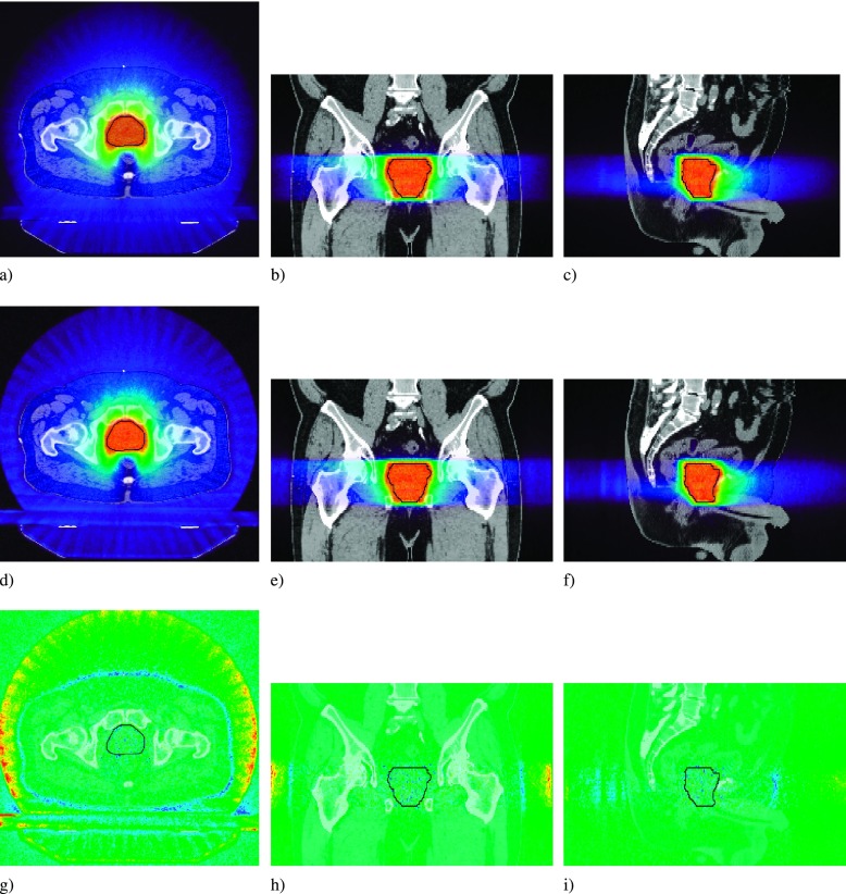
The dose distributions for the prostate plan showed no significant dependence on magnetic field strength. Representative dose profiles (Fig. 2) and dose subtraction maps show the deviation in the delivered dose within the patient. Dose differences in the target volume and throughout the patient geometry did not exceed ±3 Gy and ±4 Gy, respectively. There is a halo of high dose around the bore of the patient, and a rim of lower dose at the patient surface [Fig. 2(g)]. This is due to the magnetic field, where contamination electrons generated in the air surrounding the patient that had originally reached the patient surface, are now confined to helical trajectories in the air along the axis of the patient.
FIG. 2.
Prostate dose profiles for the B = 0 T (a), (b), and (c), and the B = 1.5 T case (d), (e), and (f). The dose difference map is for the B = 1.5 T − B = 0 T case (g), (h), and (i). PTV overlaid in black.
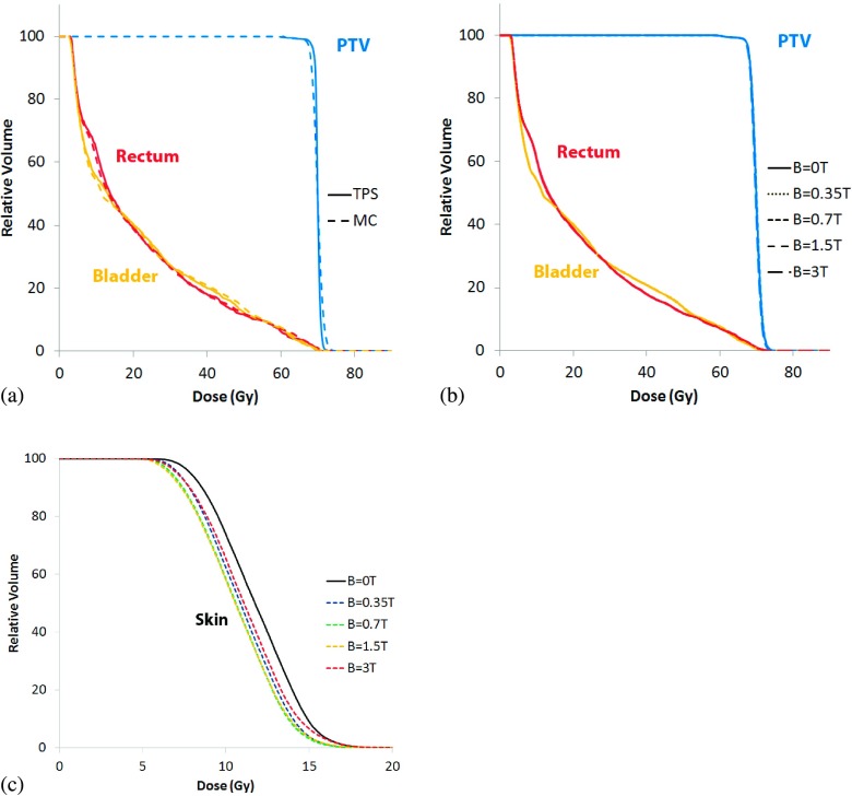
Dose–volume histograms for the prostate case are provided in Fig. 3 below. Figure 3(a) compares the DVHs determined by the treatment planning system with the Monte Carlo derived DVHs when the transverse magnetic field is turned off. Figure 3(b) plots DVHs of the target and OARs for B = 0, 0.35, 0.7, 1.5, and 3 T. As seen in the figure, there were no significant differences between the 0 T simulation and the other simulations that included a transverse magnetic field. The DHI values for all field strengths was 3.0%, with the exception of the 0.7 T case where the DHI was 3.1%. Figure 3(c) provides the skin dose calculated only on slices containing the PTV, and consistent with the dose difference maps, demonstrates a decrease in skin dose as a function of field strength. Field strengths between 0.7 and 1.5 T demonstrated the largest decrease in skin dose, of approximately 1 Gy between D90 and D10.
FIG. 3.
Prostate dose–volume histograms for (a) the TPS compared to the MC B = 0 T case, (b) the MC simulations at B = 0, 0.35, 0.7, 1.5, and 3 T, and (c) changes to skin dose at the same field strengths.
3.B. Head and neck simulation results
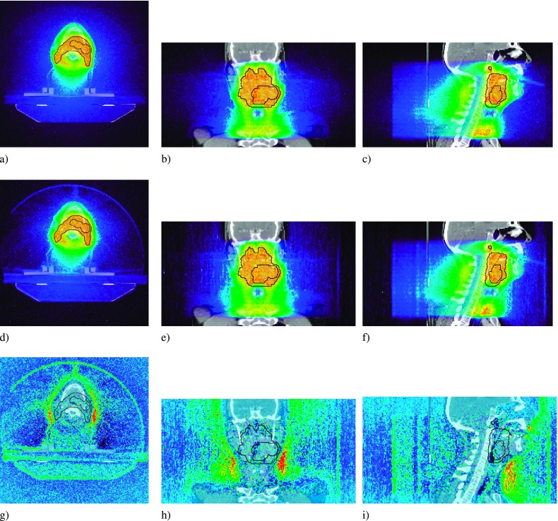
The dose distributions for the HN plan did not show significant dependence on magnetic field strength. Representative dose profiles (Fig. 4) and dose subtraction maps show that, with the exception of air cavities, dose differences did not exceed ±3 Gy in the target volume. As with the prostate case, the largest impact due to the magnetic field can again be seen in the region of air surrounding the patient, with an additional region of high air dose in the region near the neck also visible. This is due to the fact that all electrons in air are confined to spiral helices along the magnetic field lines, which are parallel to the patient axis. The resultant electrons ejected from the head and supraclavicular regions of the patient will be confined to helices in the air around the patient’s neck.
FIG. 4.
Head and neck dose profiles for the B = 0 T (a), (b), and (c), and the B = 1.5 T case (d), (e), and (f). The dose difference map is for the B = 1.5 T − B = 0 T case (g), (h), and (i). PTV overlaid in black.
Figure 5 presents DVHs for the HN case. When varying magnetic field strengths are turned on during the simulations only slight variation in the PTVs were detected [Fig. 5(b)]. For B = 0, 0.35, 0.7 T were 5.4% and the DHI values for the B = 1.5 and 3.0 T were 5.3%. Figure 5(c) shows an increase in skin dose in the presence of a magnetic field, scaling with field strength. The largest increase was for the B = 3 T case, where an increase of 3 Gy to 6 Gy was seen between D90 and D10.
FIG. 5.
Head and neck cumulative dose–volume histograms for (a) the TPS compared to the MC B = 0 T case, (b) the MC simulations at B = 0, 0.35, 0.7, 1.5, and 3 T, and (c) changes to skin dose at the same field strengths.
3.C. Lung simulation results
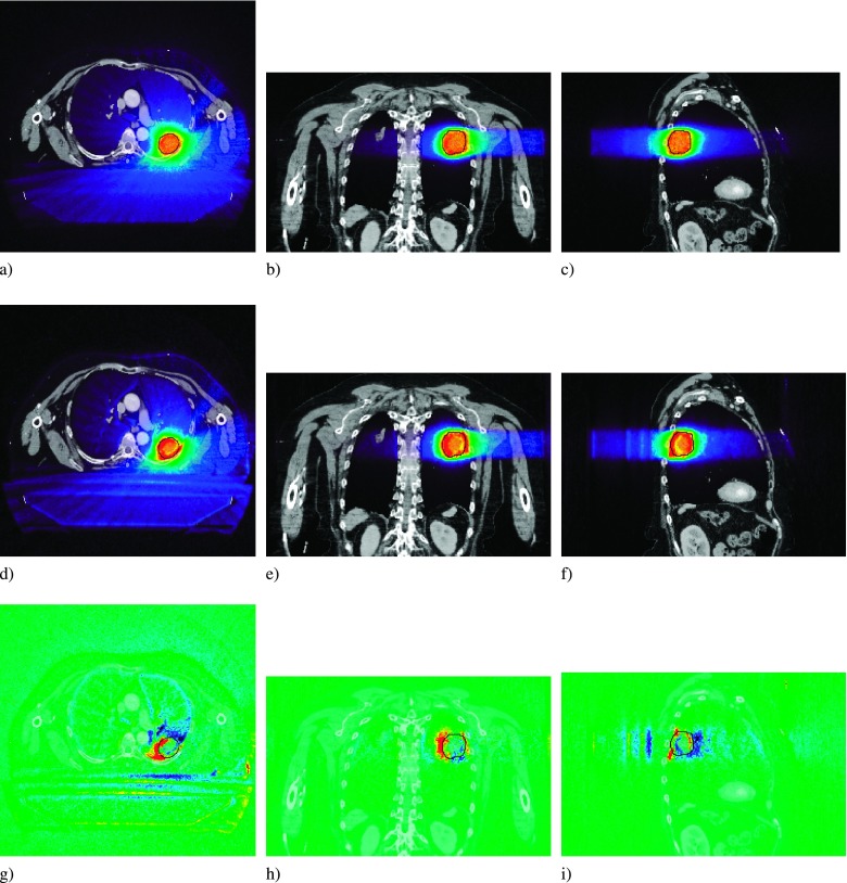
The transverse magnetic field had the greatest influence on the lung plan. The incident fluence, preferentially to be incident from the PA direction, combined with the density heterogeneity of the overall geometry, resulted in a significant perturbation to the overall dose delivered to the PTV. Two dose difference maps show the regions of over- and underdosing [Figs. 6(g)–6(i)]. The fluence, preferentially incident from the PA and right-to-left direction, results in under- and overdosing to the right-anterior and left-posterior periphery of the PTV, respectively [Fig. 6(g)]. This effect, the rotational equivalent of the lateral shift of dose penumbra seen in fixed-angle configurations, is more pronounced in the periphery of the PTV due to the compressed electron range in the lower density tissue. The sagittal slice [Fig. 6(i)] shows an increase in dose at the anterior edge of the tumor, with a corresponding reduction in dose further downstream, characteristic of the electron return effect.
FIG. 6.
Lung dose profiles for the B = 0 T (a), (b), and (c), and the B = 1.5 T case (d), (e), and (f). The dose difference map is for the B = 1.5T − B = 0 T case (g), (h), and (i). PTV overlaid in black.
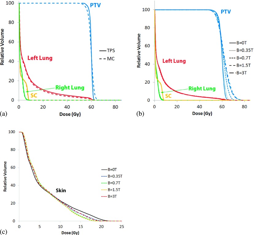
Figure 7 presents DVHs for the lung case. As seen in Fig. 7(a), the MC derived dose distribution closely matches the distribution calculated by the TPS. When varying magnetic field strengths are turned on during the simulations, overdosing to large regions of the PTV can be seen, with minimal impact to avoidance structures [Fig. 7(b)]. As expected, we find that the MC simulations predict large dose heterogeneity in the PTV and surrounding OARs where the DHIs for the B = 0, 0.35, 0.7, 1.5, and 3 T treatments were 5.5%, 7.2%, 10.1%, 20.1%, and 14.2%, respectively. Unlike the previous two cases, the PTV in the lung plan exhibits the greatest influence due to the magnetic field, with small regions of the PTV receiving slightly lower dose, and larger regions receiving much higher dose.
FIG. 7.
Lung cumulative dose–volume histograms for (a) the TPS compared to the MC B = 0 T case, (b) the MC simulations at B = 0, 0.35, 0.7, 1.5, and 3 T, and (c) changes to skin dose at the same field strengths.
Skin dose [Fig. 7(c)] for the lung case decreased for the 25% of skin receiving the highest dose, with D10 showing a decrease of over 2 Gy at B = 0.7 T and B = 1.5 T. The remaining 75% of skin received an increase of approximately 0.5 Gy in dose.
In order to further quantify the results shown in Figs. 2–7, dose differences between MC simulations and TPS at D95 and D5, and DHIs of the PTVs for the results shown in Figs. 2–7 are presented in Tables I and II.
TABLE I.
Comparison of D95 and D5 between the MC and TPS dose calculations for PTV in the three test cases. The right column is percent deviation given by (TPS-MC/TPS) × 100.
| TPS (Gy) | MC (Gy) | Deviation (%) | ||
|---|---|---|---|---|
| Prostate | D95 | 68.9 | 67.9 | 1.4 |
| D5 | 71.1 | 72.1 | −1.4 | |
| Head and neck | D95 | 66.9 | 65.5 | 2.0 |
| D5 | 71.5 | 73.5 | −2.7 | |
| Lung | D95 | 57.6 | 55.8 | 3.1 |
| D5 | 61.5 | 63.1 | −2.6 |
TABLE II.
Summary of the DHI values in each case with varying magnetic field strengths.
| DHI (%) | |||
|---|---|---|---|
| Head and neck | Prostate | Lung | |
| B = 0T | 5.4 | 3.0 | 5.5 |
| B = 0.35 T | 5.4 | 3.0 | 7.2 |
| B = 0.7 T | 5.4 | 3.1 | 10.1 |
| B = 1.5 T | 5.5 | 3.0 | 20.1 |
| B = 3 T | 5.5 | 3.0 | 14.2 |
4. DISCUSSION
This paper presents the first comprehensive investigation on the impact of a transverse magnetic field on helical tomotherapy using Monte Carlo simulations. We considered three common clinical cases treated with a Tomotherapy® Treatment System including a prostate, HN, and lung cases. For this work, all plans were originally optimized without a magnetic field in order to appropriately quantify the impact of magnetic fields on treatment plan quality. This approach follows that presented in previous investigations on IMRT treatments integrated with transverse magnetic fields. We demonstrated that our MC simulations compared well with the TPS when no B-field was present. As consistent with literature, there is slightly more dose heterogeneity in the tumor volume predicted by the MC simulations.25
Despite the helical nature of tomotherapy, it is clear that dose perturbations from magnetic fields are unavoidable, especially in cases where large, low-density heterogeneities exist in the treatment field such as in the lung. The PTV dose coverage in the presence of the MR field and its effect worsened with B field strength. However, unlike the lung case, magnetic fields of varying strength had little influence on the target coverage in both prostate and HN TomoTherapy® plans. The relatively homogeneous anatomy minimized the possibility of dose perturbations due to the electron return effect within the patient. Additionally, the rotational symmetry of the incident fluence of the prostate and HN plans eliminated the dose perturbations along the beam path, as seen in the edges of the beam penumbra MRI-guided fixed-field IMRT studies. The lung case demonstrates the effect of the magnetic field due to an asymmetric incident beam fluence compounded by the heterogeneous geometry. The asymmetry of the incident fluence results in a shift of the secondary electrons to a region that, while largely within the PTV, deposit their dose in the lower density lung, rather than the gross tumor, resulting in a pronounced overdose to the PTV. In a geometry with more homogeneous density, such a shift would result in a dose distribution resembling the prescription, but misaligned with respect to the target. For a uniform prescription to the target, the resulting PTV dose–volume histogram from such a misalignment would reflect cold regions where the dose was shifted out of the PTV, but no increase in dose beyond the original maximum. However, in a lung case such as this, the secondary electrons resulting from the chest wall and lesion itself are shifted to a lower density portion of the PTV as well as residual lung, resulting in both cold and hot spots in the PTV relative to the original prescription. Due to the peripheral location of the target volume in this lung case, a rotationally symmetric incident fluence would still experience an asymmetric shift of the resulting dose distribution due to variation in transient charged particle equilibrium as a function of beam angle.
Previous simple phantom investigations3,7,11 have demonstrated the perturbations to surface dose due to a photon beam under the influence of a perpendicular magnetic field, including an increased buildup region due to incident contamination electrons being swept away by the magnetic field, and an increased distal dose due to EREs. In a rotational delivery configuration, the dose to air, and consequently skin dose, is a function of these two competing effects, demonstrated by the prostate and the HN case. In the prostate case, the dose map [see Figs. 2(d)–2(f)] shows a halo of increased dose to air around the patient, with a thin ring of decreased dose near the patient surface [Figs. 2(g)–2(i)]. This is a result of the ERE dose contributing less to skin dose than contamination electrons do, consistent with what is seen in literature when using equal, opposed beams.26 As the analytical transfer function method used to simulate the modulation of the MLCs does not transport electrons from the head,21 the decrease in skin dose in the presence of a magnetic field is solely due to the removal of contamination electrons generated in the air surrounding the patient. Therefore, the decrease in skin dose due to a magnetic field seen in the prostate case may be even more pronounced with the inclusion of head contamination electrons. These results are consistent with what was seen in literature for simpler field configurations.27
In addition to contamination electrons and a rotational beam configuration, there is a subtle dependency of skin dose on the shape of the patient geometry as well, as seen in the HN case. There, we see an increase in skin dose of 3 to 6 Gy to the patient’s neck, lower jaw, and supraclavicular areas. Unlike the ERE and lateral penumbra shifts previously seen in literature, where for MV energy Linacs, the dose perturbations due to the effects peak at ∼B = 1.5 T and then decrease for lower and higher field strengths, this increase in dose scales linearly with magnetic field up to the 3 T limit of our investigation. We hypothesize that this excess dose to air near the neck region is a novel effect due to electrons liberated near the head and supraclavicular regions, being confined to field lines parallel to the patient axis, a consequence of our tangential field configuration. In concave regions of a patient geometry, electrons may become confined to field lines that ultimately intersect the patient geometry. As these intersection points need not be confined to the extent of the incident photon beam, it is an effect that should be carefully considered when treating near any concave geometry. A caveat to this however, is that since we did not model contamination electrons from the accelerator head itself, it is possible that the decrease in skin dose due to the magnetic field sweeping away contamination electrons could offset the increase due to this effect.
In the lung case, it is apparent from the dose difference map [Figs. 6(g)–6(i)] that the decrease in dose to the highest dosed regions of skin is a result of contamination electrons liberated from within the couch not reaching the patient once a magnetic field is applied. However, it is clear that any gap between patient skin and couch would not likely physically exist. As such, the majority of the decrease in skin dose can likely be attributed to misalignment of the replacement couch. The small increase in skin dose for the majority of the skin is a real effect, however, owing to the preferentially PA direction of the radiation beam. The thin border of higher dose along the anterior surface of the patient [Fig. 6(g)] corresponding to the 0.5 Gy increase in dose seen in the skin DVH [Fig. 7(c)] is still the result of ERE exit dose, but spread out due to the rotational beam. As with head and neck case, it is unclear about the extent of this effect when fully accounting for contamination electrons.
5. CONCLUSION
The purpose of this study was to examine the dosimetric implications of a rotational MRIgRT treatment modality, the engineering of which was explored in literature previously.6 The perturbations due to magnetic fields perpendicular to the direction of the photon beam, which manifest along a beam’s depth at interfaces as ERE dose, and along a beam’s profile as regions of asymmetric over- and underdosing, are mitigated in certain configurations. More homogeneous geometries such as prostate show minimal ERE effects, and the rotational symmetry of the incident fluence serves to naturally minimize and cancel out perturbations that occur on the edge of beam penumbra in fixed-field scenarios, offering an absolute benefit of decreased skin dose over its field-free counterpart. While other groups have demonstrated that plan optimization using beamlets generated with a magnetic field can mitigate many of the effects seen in this investigation,13,28 the lung and HN case also illustrate the care that must be taken when judging plans created for MRIgRT treatments. While changes to the lung PTV due to a magnetic field were pronounced, the relatively larger left lung OARshowed little impact in the DVH due to the localized effects of the dose perturbation. The HN case demonstrates the potential need to consider localized patches of skin in concave regions of patient geometry that intersect field lines, a situation unique to the physics of MRIgRT. Even a homogeneous case such as prostate may contain local regions that warrant such consideration during the use of a rectal balloon, where rectal wall becomes a key ERE interface in a volumetrically large structure. In the future, it may be beneficial to create additional optimization structures that specificallytarget localized effects only seen in the presence of magnetic fields.
ACKNOWLEDGMENTS
This work was partially supported by the “UW Radiological Training Grant” No. T31 CA0090206.
REFERENCES
- 1.Lagendijk J. J. W.et al. , “MRI/linac integration,” Radiother. Oncol. 86(1), 25–29 (2008). 10.1016/j.radonc.2007.10.034 [DOI] [PubMed] [Google Scholar]
- 2.Fallone B. G.et al. , “First MR images obtained during megavoltage photon irradiation from a prototype integrated linac-MR system,” Med. Phys. 36(6), 2084–2088 (2009). 10.1118/1.3125662 [DOI] [PubMed] [Google Scholar]
- 3.Kirkby C., Murray B., Rathee S., and Fallone B. G., “Lung dosimetry in a linac-MRI radiotherapy unit with a longitudinal magnetic field,” Med. Phys. 37(9), 4722–4732 (2010). 10.1118/1.3475942 [DOI] [PubMed] [Google Scholar]
- 4.Oborn B. M., Metcalfe P. E., Butson M. J., and Rosenfeld A. B., “Monte Carlo characterization of skin doses in 6 MV transverse field MRI-linac systems: Effect of field size, surface orientation, magnetic field strength, and exit bolus,” Med. Phys. 37(10), 5208–5217 (2010). 10.1118/1.3488980 [DOI] [PubMed] [Google Scholar]
- 5.Dempsey J. F.et al. , “A device for realtime 3D image-guided IMRT,” Int. J. Radiat. Oncol., Biol., Phys. 63, S202 (2005). 10.1016/j.ijrobp.2005.07.349 [DOI] [Google Scholar]
- 6.Kron T., Eyles D., John S. L., and Battista J., “Magnetic resonance imaging for adaptive cobalt tomotherapy: A proposal,” J. Med. Phys. 31(4), 242–254 (2006). 10.4103/0971-6203.29194 [DOI] [PMC free article] [PubMed] [Google Scholar]
- 7.Kirkby C., Stanescu T., Rathee S., Carlone M., Murray B., and Fallone B. G., “Patient dosimetry for hybrid MRI-radiotherapy systems,” Med. Phys. 35(3), 1019–1027 (2008). 10.1118/1.2839104 [DOI] [PubMed] [Google Scholar]
- 8.Yang Y. and Bednarz B., “SU-E-T-678: Monte Carlo investigation on dose perturbations in the lung due to constant magnetic fields during MRIgRT,” Med. Phys. 38, 3646 (2011). 10.1118/1.3612640 [DOI] [Google Scholar]
- 9.Yang Y. M. and Bednarz B., “Consistency evaluation between EGSnrc and geant4 charged particle transport in an equilibrium magnetic field,” Phys. Med. Biol. 58(4), N47–N58 (2013). 10.1088/0031-9155/58/4/n47 [DOI] [PubMed] [Google Scholar]
- 10.Raaymakers B. W., Raaijmakers A. J. E., Kotte A. N. T. J., Jette D., and Lagendijk J. J. W., “Integrating a MRI scanner with a 6 MV radiotherapy accelerator: Dose deposition in a transverse magnetic field,” Phys. Med. Biol. 49(17), 4109–4118 (2004). 10.1088/0031-9155/49/17/019 [DOI] [PubMed] [Google Scholar]
- 11.Raaijmakers A. J. E., Raaymakers B. W., and Lagendijk J. J. W., “Integrating a MRI scanner with a 6 MV radiotherapy accelerator: Dose increase at tissue–Air interfaces in a lateral magnetic field due to returning electrons,” Phys. Med. Biol. 50(7), 1363–1376 (2005). 10.1088/0031-9155/50/7/002 [DOI] [PubMed] [Google Scholar]
- 12.Raaijmakers A. J. E., Raaymakers B. W., van der Meer S., and Lagendijk J. J. W., “Integrating a MRI scanner with a 6 MV radiotherapy accelerator: Impact of the surface orientation on the entrance and exit dose due to the transverse magnetic field,” Phys. Med. Biol. 52(4), 929–939 (2007). 10.1088/0031-9155/52/4/005 [DOI] [PubMed] [Google Scholar]
- 13.Raaijmakers A. J. E., Hårdemark B., Raaymakers B. W., Raaijmakers C. P. J., and Lagendijk J. J. W., “Dose optimization for the MRI-accelerator: IMRT in the presence of a magnetic field,” Phys. Med. Biol. 52(23), 7045–7054 (2007). 10.1088/0031-9155/52/23/018 [DOI] [PubMed] [Google Scholar]
- 14.Cao D., Holmes T. W., Afghan M. K. N., and Shepard D. M., “Comparison of plan quality provided by intensity-modulated arc therapy and helical tomotherapy,” Int. J. Radiat. Oncol., Biol., Phys. 69(1), 240–250 (2007). 10.1016/j.ijrobp.2007.04.073 [DOI] [PubMed] [Google Scholar]
- 15.Oliver M., Ansbacher W., and Beckham W. A., “Comparing planning time, delivery time and plan quality for IMRT, rapidArc and tomotherapy,” J. Appl. Clin. Med. Phys. 10(4), 117–131 (2009). 10.1120/jacmp.v10i4.3068 [DOI] [PMC free article] [PubMed] [Google Scholar]
- 16.Rao M.et al. , “Comparison of Elekta VMAT with helical tomotherapy and fixed field IMRT: Plan quality, delivery efficiency and accuracy,” Med. Phys. 37(3), 1350–1359 (2010). 10.1118/1.3326965 [DOI] [PubMed] [Google Scholar]
- 17.Kerkhof E. M.et al. , “A new concept for non-invasive renal tumour ablation using real-time MRI-guided radiation therapy,” BJU Int. 107(1), 63–68 (2011). 10.1111/j.1464-410x.2010.09458.x [DOI] [PubMed] [Google Scholar]
- 18.Agostinelli S.et al. , “ geant4 a simulation toolkit,” Nucl. Instrum. Methods Phys. Res., Sect. A 506(3), 250–303 (2003). 10.1016/S0168-9002(03)01368-8 [DOI] [Google Scholar]
- 19.Sterpin E., Salvat F., Cravens R., Ruchala K., Olivera G. H., and Vynckier S., “Monte Carlo simulation of helical tomotherapy with penelope,” Phys. Med. Biol. 53(8), 2161–2180 (2008). 10.1088/0031-9155/53/8/011 [DOI] [PubMed] [Google Scholar]
- 20.Sterpin E., Salvat F., Olivera G., and Vynckier S., “Monte Carlo evaluation of the convolution/superposition algorithm of Hi-Art™ tomotherapy in heterogeneous phantoms and clinical cases,” Med. Phys. 36(5), 1566–1575 (2009). 10.1118/1.3112364 [DOI] [PubMed] [Google Scholar]
- 21.Sterpin E., Salvat F., Olivera G. H., and Vynckier S., “Analytical model of the binary multileaf collimator of tomotherapy for Monte Carlo simulations,” J. Phys.: Conf. Ser. 102(1), 012022 (2008). 10.1088/1742-6596/102/1/012022 [DOI] [Google Scholar]
- 22.ICRU, Tissue Substitutes in Radiation Dosimetry and Measurement (ICRU, Bethesda, MD, 1989). [Google Scholar]
- 23.Lu W., “A non-voxel-based broad-beam (NVBB) framework for IMRT treatment planning,” Phys. Med. Biol. 55(23), 7175–7210 (2010). 10.1088/0031-9155/55/23/002 [DOI] [PubMed] [Google Scholar]
- 24.Sterpin E., Chen Y., Chen Q., Lu W., Mackie T. R., and Vynckier S., “Monte Carlo-based simulation of dynamic jaws tomotherapy,” Med. Phys. 38(9), 5230–5238 (2011). 10.1118/1.3626486 [DOI] [PubMed] [Google Scholar]
- 25.Zhuang T.et al. , “Dose calculation differences between Monte Carlo and pencil beam depend on the tumor locations and volumes for lung stereotactic body radiation therapy,” J. Appl. Clin. Med. Phys. 14(2), 4011–4024 (2013). 10.1120/jacmp.v14i2.4011 [DOI] [PMC free article] [PubMed] [Google Scholar]
- 26.Raaijmakers A. J. E., Raaymakers B. W., and Lagendijk J. J. W., “Magnetic-field-induced dose effects in MR-guided radiotherapy systems: Dependence on the magnetic field strength,” Phys. Med. Biol. 53(4), 909–923 (2008). 10.1088/0031-9155/53/4/006 [DOI] [PubMed] [Google Scholar]
- 27.Oborn B. M., Metcalfe P. E., Butson M. J., Rosenfeld A. B., and Keall P. J., “Electron contamination modeling and skin dose in 6 MV longitudinal field MRIgRT: Impact of the MRI and MRI fringe field,” Med. Phys. 39(2), 874–890 (2012). 10.1118/1.3676181 [DOI] [PubMed] [Google Scholar]
- 28.Bol G. H., Hissoiny S., Lagendijk J. J. W., and Raaymakers B. W., “Fast online Monte Carlo-based IMRT planning for the MRI linear accelerator,” Phys. Med. Biol. 57(5), 1375–1385 (2012). 10.1088/0031-9155/57/5/1375 [DOI] [PubMed] [Google Scholar]


