Abstract
Purpose
Our goal was to optimize procedures for assessing shapes, sizes, and other quantitative metrics of retinal pigment epithelium (RPE) cells and contact- and noncontact-mediated cell-to-cell interactions across a large series of flatmount RPE images.
Methods
The two principal methodological advances of this study were optimization of a mouse RPE flatmount preparation and refinement of open-access software to rapidly analyze large numbers of flatmount images. Mouse eyes were harvested, and extra-orbital fat and muscles were removed. Eyes were fixed for 10 min, and dissected by puncturing the cornea with a sharp needle or a stab knife. Four radial cuts were made with iridectomy scissors from the puncture to near the optic nerve head. The lens, iris, and the neural retina were removed, leaving the RPE sheet exposed. The dissection and outcomes were monitored and evaluated by video recording. The RPE sheet was imaged under fluorescence confocal microscopy after staining for ZO-1 to identify RPE cell boundaries. Photoshop, Java, Perl, and Matlab scripts, as well as CellProfiler, were used to quantify selected parameters. Data were exported into Excel spreadsheets for further analysis.
Results
A simplified dissection procedure afforded a consistent source of images that could be processed by computer. The dissection and flatmounting techniques were illustrated in a video recording. Almost all of the sheet could be routinely imaged, and substantial fractions of the RPE sheet (usually 20–50% of the sheet) could be analyzed. Several common technical problems were noted and workarounds developed. The software-based analysis merged 25 to 36 images into one and adjusted settings to record an image suitable for large-scale identification of cell-to-cell boundaries, and then obtained quantitative descriptors of the shape of each cell, its neighbors, and interactions beyond direct cell–cell contact in the sheet. To validate the software, human- and computer-analyzed results were compared. Whether tallied manually or automatically with software, the resulting cell measurements were in close agreement. We compared normal with diseased RPE cells during aging with quantitative cell size and shape metrics. Subtle differences between the RPE sheet characteristics of young and old mice were identified. The IRBP−/− mouse RPE sheet did not differ from C57BL/6J (wild type, WT), suggesting that IRBP does not play a direct role in maintaining the health of the RPE cell, while the slow loss of photoreceptor (PhR) cells previously established in this knockout does support a role in the maintenance of PhR cells. Rd8 mice exhibited several measurable changes in patterns of RPE cells compared to WT, suggesting a slow degeneration of the RPE sheet that had not been previously noticed in rd8.
Conclusions
An optimized dissection method and a series of programs were used to establish a rapid and hands-off analysis. The software-aided, high-sampling-size approach performed as well as trained human scorers, but was considerably faster and easier. This method allows tens to hundreds of thousands of cells to be analyzed, each with 23 metrics. With this combination of dissection and image analysis of the RPE sheet, we can now analyze cell-to-cell interactions of immediate neighbors. In the future, we may be able to observe interactions of second, third, or higher ring neighbors and analyze tension in sheets, which might be expected to deviate from normal near large bumps in the RPE sheet caused by druse or when large frank holes in the RPE sheet are observed in geographic atrophy. This method and software can be readily applied to other aspects of vision science, neuroscience, and epithelial biology where patterns may exist in a sheet or surface of cells.
Introduction
The RPE is a continuous monolayer of interconnected, relatively uniform cuboidal cells on a thin spheroidal shell. The RPE cells function as a barrier between the neuroepithelium and the choroid. The RPE cells have numerous other functions that are tightly integrated with photoreceptor cells [1]. The RPE is integral to the function of the mammalian outer blood-retinal barrier (BRB) [2-4]. The etiology of several diseases includes breakdown of the BRB accompanied by RPE cell loss and mosaic remodeling [4-8]. RPE cell death affects the organization and shape of neighboring cells as they remodel to rescue the barrier function in the RPE sheet [9,10]. We seek to analyze large numbers of RPE cells in whole mounts to understand direct cell-to-cell and noncontact interactions that maintain the barrier function of the RPE, with the expectation that this will lead to better understanding of structural changes in normal aging and disease etiology.
Quantitative analyses of Drosophila wing epithelium development [11,12] suggest a theory of epithelial cell interactions that maintain homeostasis and cell movement under stress [13]; these may be useful guides to RPE research. There is an extensive history of qualitative studies of the topography of the RPE sheet in human [14,15], monkey [16], mouse [17-19], and other species [20-24]. However, to obtain and analyze the large numbers of cells per RPE sheet required for quantitative metrics as suggested by the Drosophila studies, we had to improve the preparation and analysis of RPE sheets.
Here, we describe our improvements to standard [25] mouse RPE dissection and preparation in text and video. We also provide a complete package of software tools refined from open-source software that allows quick, in-depth analysis of many images [20-23,26-30]. The improved tissue preparation and image analysis tools allow us to routinely analyze more than 10,000 cells per mouse RPE sheet, resulting in more robust statistical analyses that allow accurate and precise discrimination among genotype–age groups (cf., normal young and normal old mice) [31]. The interested communities of vision science, neuroscience, and epithelial biology can adopt these approaches easily.
Methods
Mouse husbandry
Mice were handled according to Association for Research in Vision and Ophthalmology (ARVO) guidelines and approved by the Emory University Institutional Animal Care and Use Committee. C57BL/6J mice were obtained from the Jackson Laboratory (Bar Harbor, ME). Homozygous rd8 mice, which also carried rpe65−/− on a mixed C57BL/6N, 129S1/Sv, and 129X1/SvJ background, were provided by Dr. T. Michael Redmond (NEI, NIH). IRBP−/− (knockouts of the IRBP [Rbp3] gene) mice originally came from Dr. Gregory Liou (Medical College of Georgia) and were backcrossed onto C57BL/6J for 10 generations. Standard mouse diet and housing conditions were as described in Johnson et al. [32]. Mice were killed using CO2 asphyxiation before dissection.
Eye preparation
The superior position was marked on the cornea with a blue “Sharpie” permanent marking pen (Sanford; series 30,000, Staples or many other office supply houses) or by cautery (Gemini Cautery System, Fisher Scientific, Pittsburgh, PA). Immediately following orientation, oculus dexter (OD, i.e., right eye) globes were enucleated and fixed in phosphate-buffered 10% formalin (Fisher Scientific, catalog #SF100–4) for 10 min at room temperature; subsequently, these eyes were used in flatmounting. OD globes were rapidly washed three rapidly with Hank’s Buffered Saline Solution (HBSS 1x; Mediatech, Inc., Herndon, VA; catalog #21–022-CM).
Dissection
Two microscope systems, the Seiler Askania SMC4 (Askania, Rathenow, Germany) and the Olympus SZX2-ZB16 microscope (Olympus, Center Valley, PA), described in Johnson et al. [32], were employed for the following flatmount dissections. Dumont #5 forceps (World Precision Instruments, Inc., Sarasota, FL; item #500,342), 8 cm STR Vannas scissors (World Precision Instruments, Inc., item #14,003), and a 23- to 18-gauge needle (for making the initial puncture in the center of the cornea) were needed to cut and manipulate the globe.
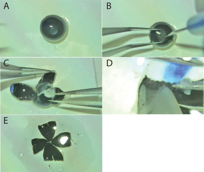
Right eyes were cleaned of excess liquid and placed on a Superfrost/Plus microscope slide (Fisher Scientific, catalog #12–550–15; movie, Figure 1). Muscle and fat surrounding the globe were cut to create a smooth outer surface, without puncturing the globe (Figure 2A, photograph of a smooth globe). Finally, the optic nerve was snipped at its base.
Figure 1.
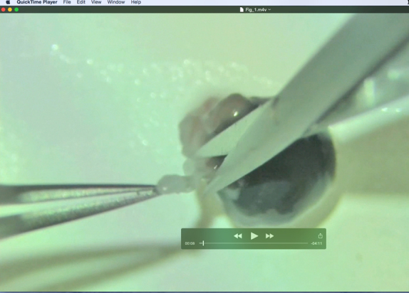
Flatmount dissection movie. This movie was filmed with an Olympus SZX16 with a SZX2-RFA16 reflected light fluorescence illuminator modified with a halogen lamp to provide true coaxial illumination and an HD video camera (Video 1). It outlines the dissection in a six-step process of extra-ocular tissue removal, corneal incision, radial cuts, flap opening, lens removal, iris removal, and retina removal.
Figure 2.
Still-shots of an RPE flatmount dissection. A: The smooth surface of an eye globe after removal of fat and extra-ocular muscles. B: Corneal penetration with a stab knife as forceps steady the eye. C: Scissors insertion at the corneal puncture cutting along the radial axis toward the optic nerve. D: The flattened globe, with neural retina remaining, after four radial cuts. E: Neural retina removal exposes the RPE for subsequent staining.
While steadying the eye with forceps, a small puncture was made in the center of the cornea (Figure 2B, still shot of corneal puncture) with a microsurgical stab knife (Surgical Specialties Corporation, Reading, PA, catalog #72–1501) or a 28- to 30-gauge needle, creating an insertion site for the scissors. Vannas scissors were inserted into the corneal puncture and four symmetric radial cuts were made starting from the corneal center and ending immediately before the optic nerve head. These four radial cuts, manifesting as petals, were gently flattened onto the filter paper from their spherical shape using forceps (Figure 2C, still shot of radial flaps, lens in place). The lens was removed with forceps and the eyecup was kept moist with a drop of HBSS (approximately 20 μl).
Using #5 Dumont forceps, the surgeon grasped and peeled the neural retina away from the ciliary body (Figure 2D). After the retina was released from the ciliary body for each flap, the neural retina was lifted and removed by going under the retina and grasping the optic nerve head with the forceps and lifting the retina off. Last, the corneal tab marked with the blue Sharpie was cut off, defining the superior orientation for subsequent microscopy (Figure 2E, final flattened mount).
Immunohistochemistry
ZO-1 staining
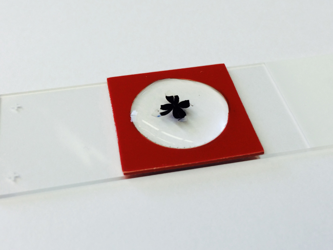
Tight junctions were stained with rabbit anti-ZO-1 (Invitrogen, Grand Island, NY; catalog #61–7300). A boundary around the RPE flatmount was created using a silicone gasket (JTR20-A-1.0 isolator, PSA on one side; Grace Bio Labs, Bend, OR, product #665104). The gasket allowed for a consistent volume of blocking buffer, primary antibody, and secondary antibody that completely immersed the RPE flatmount (Figure 3). We discourage the use of “Pap pens” or grease pens to establish boundaries for immunostaining, as these may contain compounds that strongly inhibit fluorescence, or fluoresce themselves, after mounting. The flatmount was incubated in 300 μl of a “blocking buffer” consisting of 1% (w/v) bovine serum albumin (BSA; Roche Diagnostics GmbH, Mannheim, Germany, Product 03,116,956,001) and 0.1% (v/v) Triton X-100 (Sigma, St. Louis, MO) in HBSS for 1 h at room temperature in a humidified chamber. Blocking buffer was aspirated with a microcapillary pipette tip.
Figure 3.
Completed flatmount immersed in antibody. All antibody staining is performed directly on a microscope slide. A silicone gasket creates a 300 µl well surrounding the flatmounted RPE.
The RPE flatmount was incubated in the primary antibody, a 1:100 dilution of rabbit anti-ZO-1 in 300 μl blocking buffer solution, for 16 h at room temperature. Mounts were stored in a humidified chamber to avoid evaporation of the antibody and subsequent dehydration of the RPE flatmount.
Following 16 h of incubation, the primary antibody was removed with five 300 μl rinses of HBSS with 0.1% (v/v) Triton X-100 for 2 min each rinse. Flatmounts were incubated with a secondary antibody, a 1:1,000 dilution of goat–anti-rabbit immunoglobulin G (IgG) conjugated with Oregon Green (Invitrogen; O-11038) in blocking buffer, for 1 h at room temperature in a black container. Handling of the secondary antibody was conducted under dim light to avoid degradation of the conjugated fluorophore. After 1 h of incubation, the secondary antibody was rinsed off with 300 μl HBSS with 0.1% (v/v) Triton X-100 and 20 μg/ml propidium iodide five times for 2 min and twice with 300 μl HBSS with 0.1% (v/v) Triton X-100. The silicone gasket was removed and flatmounts were mounted in Vectashield Hardset (H-1400; Vector Labs, Burlingame, CA), with a 24×40 mm coverslip (VWR micro cover glass; catalog #48,393 230). The mounting medium solidifies overnight at room temperature in the dark, as described in the manufacturer’s instructions for Hardset. We typically store the slides at room temperature in the dark until imaging. Regardless of storage temperature after curing, the signal will dissipate significantly after a week, so imaging needs to be done promptly.
Imaging
Image acquisition
Confocal microscopy was performed using a Nikon Ti inverted microscope with C1 confocal scanner (Nikon Instruments, Melville, NY) as detailed in Johnson et al. [32]. The software used to capture the images was Nikon EZ-C1 Gold version 3.80. Oregon Green was excited using the argon gas 488 nm laser line and emissions were collected through a 515/30 bandpass filter. Images were acquired no less than 8 h and no more than 7 days after mounting with Vectashield Hardset to ensure adequate drying of mounting media and to avoid degradation of the fluorophore.
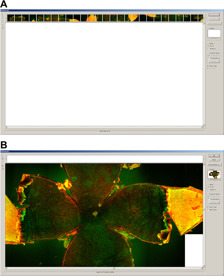
Using an automated XY stage control within the EZ-C1 software, the entire flatmount was systematically imaged with a 10× objective lens and a medium confocal pinhole. Typically, 25 to 36 images were required to cover the entire RPE flatmount with adequate overlap of adjacent images. Ten micrometer Z-stacks were captured to allow for uneven tissue. Maximum intensity volume projections were used for subsequent analysis. The software was set to acquire at 1.243164 microns/pixel. Files were converted from Nikon IDS format to BMP in ImageJ using the JavaScript in Appendix 1. They were photomerged (Figure 4) using Photoshop CS2 (Adobe Inc., San Jose, CA). More recent versions of Photoshop employ a photomerging algorithm that warps the images, and we found that the warping affected accurate assembly and distorted cells on the boundaries of one image to the next. This should be kept in mind if using later versions of Photoshop or other image-stitching software.
Figure 4.
The image stitching or merging process in Photoshop. A: Open image files in the Photoshop CS2 photomerge utility. B: Final arrangement of stitched images to create a photomerged image. Each individual image acquired by the Nikon microscope was merged using the Adobe Photoshop CS2 Photomerge feature. Merging the entire flatmount allows for orienting and sampling the whole RPE sheet.
Image processing
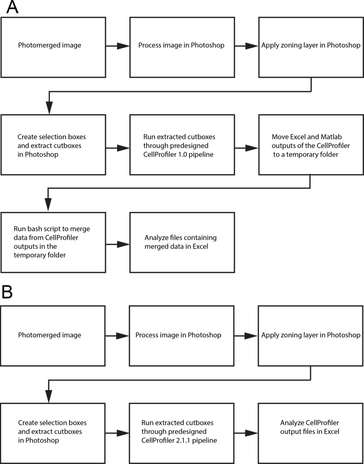
Two approaches were taken to image processing and analysis, and flowchart representations of each are shown in Figure 5. The first approach (Figure 5A; Method 1) was developed for use with CellProfiler version 1.0, and requires preprocessing of the images. The second approach relies on an updated CellProfiler version 2.1.1 (Figure 5B; Method 2) and requires less preprocessing.
Figure 5.
Image processing. A: Old pipeline compatible with CellProfiler 1.x. B: A new pipeline compatible with CellProfiler 2.x.
In the first approach (Figure 5A), images were stitched together using the Photoshop Photomerge utility, and uneven background fluorescence was removed using a Photoshop “Action” entitled ProcessImage (Appendix 2). The ProcessImage Action subtracted a Gaussian blurred copy of the image from the original. After this, a linear burn of the Gaussian blur–subtracted image was used to eliminate any non-specific green signal from RPE nuclei, using a high contrast grayscale image from propidium iodide staining in the red channel. Finally, this Action refocused the output signal in the green channel and saved the image into a specified folder, appending the original filename. See the “before” and “after” pictures in Figure 6.
Figure 6.
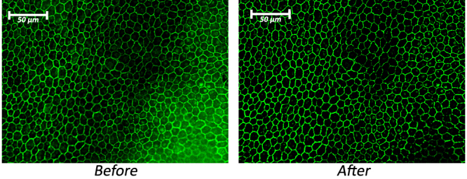
A section of stained RPE cells. The “before” picture was acquired through the EZ-C1 software accompanying the Nikon microscope and is displayed without any image processing. The “after” picture was processed using the ProcessImage action script, created for Adobe Photoshop CS3 and included in Appendix 2. The script’s function was to increase the intensity of the green border staining relative to the background noise found within the cells and balance illumination across the image.
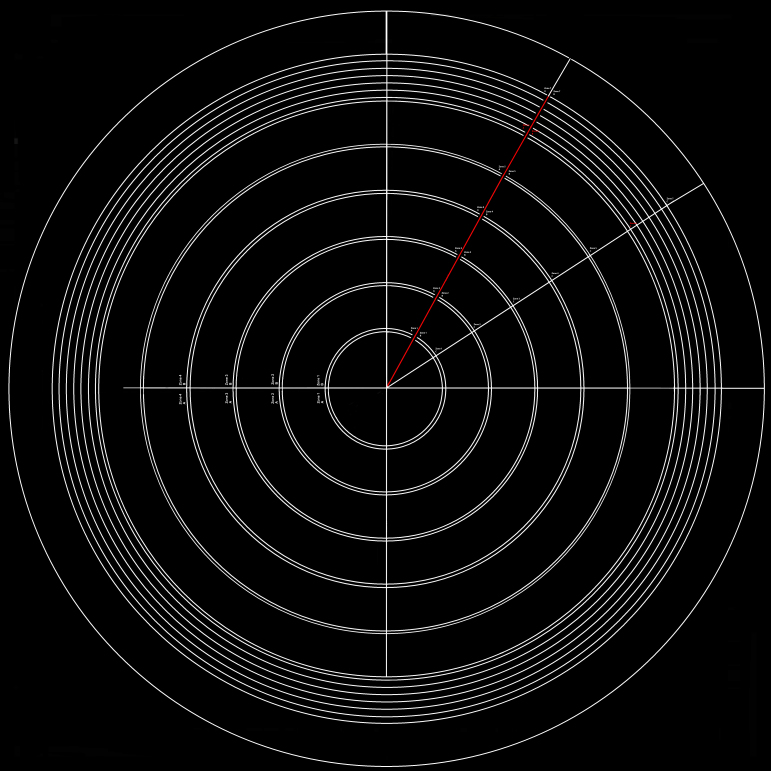
A grid (Figure 7 and Appendix 3) made of concentric circles, starting 400 microns from the optic nerve, with concentric circles placed 320 microns apart, was made 30% opaque and overlaid as a second layer above the photomerged and background-subtracted whole flatmount. These concentric circles formed zones (each one a quarter of a ring) at specific intervals from the center of the optic nerve head. Each zone was 300 microns in width and spaced 20 microns apart from adjacent zones.
Figure 7.
Zone location by ring and petal. A partially opaque grid used to map the RPE flatmount is overlaid in Adobe Photoshop with its origin positioned at the center of the optic nerve. The grid consists of concentric circles beginning 400 microns from the optic nerve. Pairs of double concentric circles, 320 microns apart, create sampling regions. Each subsequent sampling region begins 20 microns away from the preceding one. This grid along with orientation of the superior petal allows for position specificity that includes distance from the optic nerve and anatomic orientation. The grid is available for download in Appendix 3.
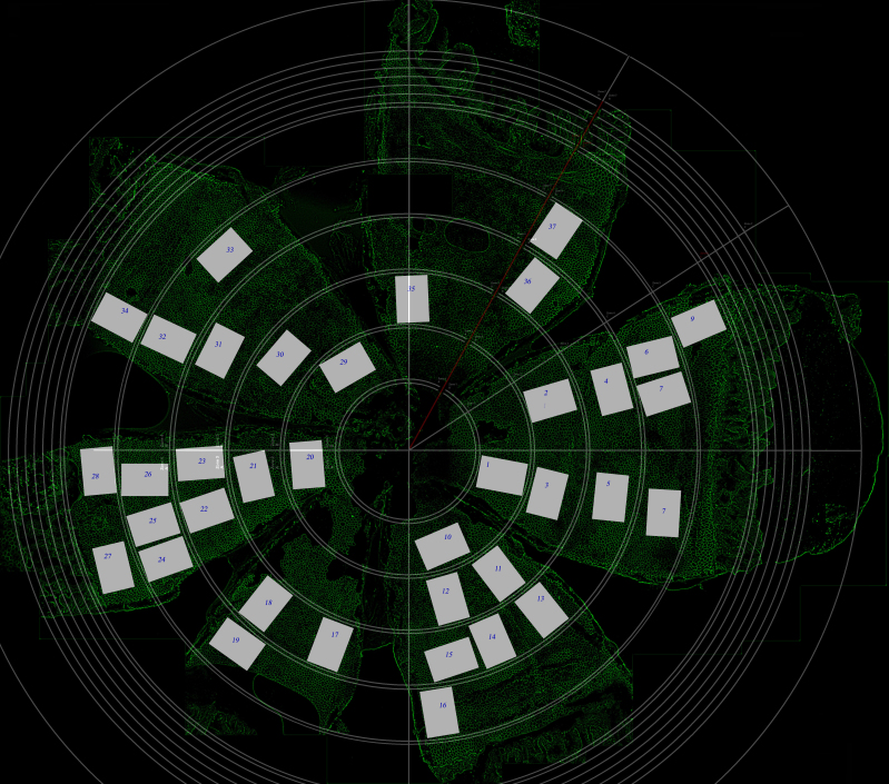
Sampling boxes (with dimensions of 265×180 pixels), were placed within each zone. We placed as many boxes as possible in each zone, excluding boxes where the RPE sheet was damaged or had obvious artifacts. We avoided zone borders, concentrations of secondary signal over 6 microns in diameter, or areas above 40 microns in diameter with dim or no staining (box in grid, Figure 8).
Figure 8.
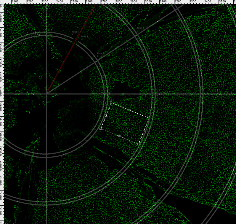
Positioning a sampling box. A 265×180 micron sampling box, creating using Adobe Photoshop’s rectangular marquee, was placed within sampling regions created by the grid. A maximum number of sampling boxes were placed in each sampling region allowing for full rotation of the box and avoiding grid borders, concentrations of secondary signal above 7.5 microns in diameter or areas of 50 microns in diameter with dim or no staining. The action script creating this 265×180 pixel box is available for download as GrabSelection, Appendix 5.
The first 265×180 box was created using a Photoshop CS3 script called “SetSelection” (Appendix 4). After this first box was placed, one of the four scripts “grab_selection_20N,” “grab_selection_20S,” “grab_selection_20E,” or “grab_selection_20W” (Appendix 5) was used to cut out the box, straighten it, make the image the full size of its canvas, rotate some 90° so that all were in landscape perspective (width greater than height; for subsequent CellProfiler analysis, see the next paragraph), and place it in a folder with a unique file name ending in a sequentially incremented number. The resulting images (Figure 9) were suitable for analysis within CellProfiler version 1.0.
Figure 9.
A fully sampled RPE flatmount. Depending on staining quality, approximately 30 boxes were sampled throughout each sheet. Each section of RPE used for analysis is numbered with its corresponding label on the flatmount.
Image analysis
CellProfiler
CellProfiler is a high throughput, well-maintained open-source program that is designed to analyze batches of images through customizable scripts called “pipelines” [33]. A pipeline called cp1-mouse.cp (used with CellProfiler 1.0 and given in Appendix 6) was created to analyze RPE cells, but could be more broadly applied to any epithelial monolayer.
CellProfiler (version 1.0) was installed on a computer running Mac OS X version 10.5.6 with a 2×2.66 GHz Dual-core Intel Xeon Processor and 4GB 667 MHz DDR2 FB-DIMM of memory. The pipeline was loaded into the program. A source folder containing all sample boxes from one eye was created and designated the “default image folder.” A “default output folder” was designated in a similar manner. The pipeline was executed, creating a set of output data files for each 265×180 pixel sampling box.
Merging neighbor data
To ensure that CellProfiler 1.0 did not include partial cells that were cut off by the edge of each sample box image, all counting and measurements were carried out only for cells that did not share an edge with the image border. These partial cells are sometimes called “border elements.” However, to obtain accurate counts for the “number of neighbors” statistic, specifically for those cells that neighbor cells on the image border, CellProfiler had to first identify all cells in one set of data (DefaultOUT.mat_inc_id_objects.xls) and then identify all cells excluding those touching the image border in another set of data (DefaultOUT.mat_id_objects.xls). Without using both datasets, the cells touching cells on the image border would have an artificially low number of neighbors (compare the left and right images in Figure 10).
Figure 10.

Counting of cell sides. CellProfiler output images for counting the number of neighboring cells. A: Cells that are not touching the border of the image and are within a specified size range. All cell measurements reflect cells within a specific size range that do not touch the border of an image. This image excludes these border elements. B: A second identification of cells was performed to obtain accurate counts for cells that neighbored cells touching the border. This identification included all cells (and all partial cells), independent of their location within the image. The number of neighboring cells for the cells next to border cells was the only statistic that was altered through this second round of identification.
A program was created to replace the values in the “number of neighbors” field of the two latter files. This was done with a shell script, “bash_analysis” (Appendix 7). The resulting summary file was arranged according to each CellProfiler input image.
Filtering out inaccurately identified cells
Depending on the quality of a given sample box, the step involving filtering out inaccurately identified cells was useful for excluding images in which cells were not accurately counted. CellProfiler’s object (cell) identification was qualitatively judged by its primauto output figure (Figure 11 [bottom]), which showed identified objects outlined in green and unidentifiable objects outlined in red. To avoid the possibility of subjective bias when selecting images, only images that met a specified threshold for the “percent of the image consisting of objects” were accepted. For this set of data, the threshold was set at a minimum of 57.5%. This percentage may seem low, but the edge effect, which tags partial cells on the border as “unidentified,” markedly reduces this percentage despite a lack of abnormalities of these partial cells. Thus, this threshold represents a number 10% less than that of a 265×180 pixel image consisting wholly of identifiable objects.
Figure 11.
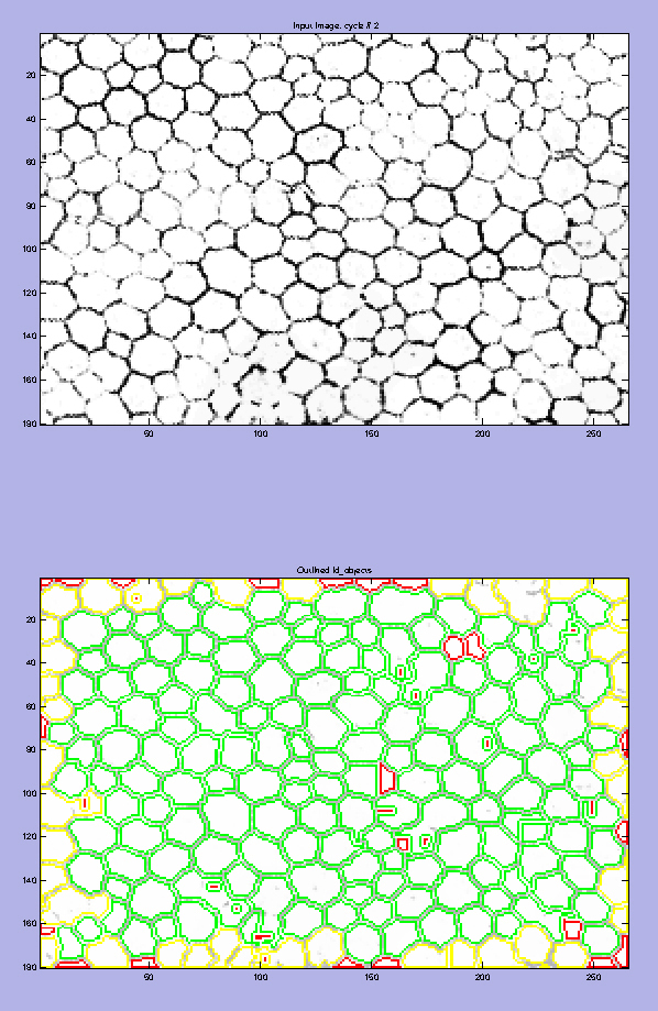
Comparison of an input image and its resulting segmentation. A: The input image is shown at the top. The primauto output file (lower image) from CellProfiler shows cells within the image that were identified as objects to count and measured in green. Those cells that it does not recognize as objects are outlined in red, and those that touch the border are outlined in yellow. These images may be used as a qualitative judge of CellProfiler’s ability to identify objects in a given image. The “percent of the image consisting of objects” reported by CellProfiler was used as a quantitative threshold when screening for accurate cell identification.
CellProfiler validation and sample sizes
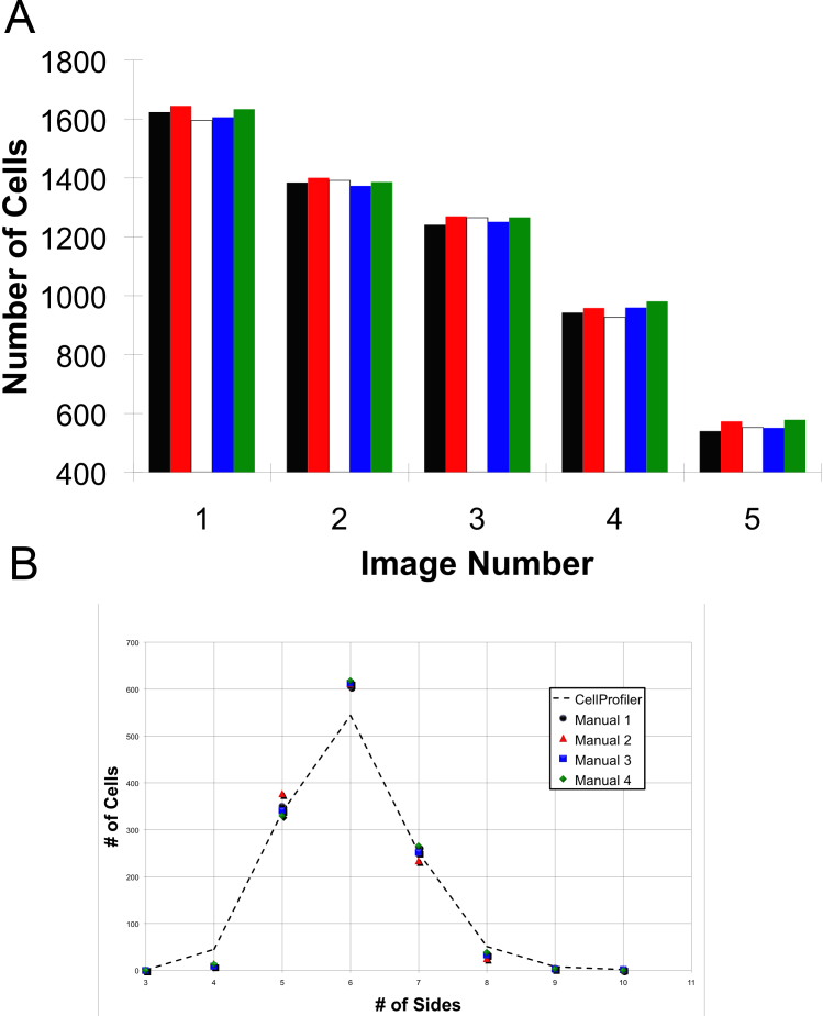
Five different images were hand counted. Each of the five images varied in number of aberrations in staining and image quality. Furthermore, the five images varied in size from approximately 550 to 1,600 cells per image. Experiments were designed with the minimum number of images with hand-enumerated cells to minimize the manual time and effort. The experiment had only two arms, first, manual counting, and second, automated counting of the same images. Two characteristics of the image were collected, namely the total number of cells (Figure 12A) and the number of cells with a specified number of neighbors (Figure 12B). We found that there were negligible numbers of cells with three sides (less than or equal to one per thousand cells), and the same was true of cells with 10 or more sides. Because of the tiny numbers of these cells, they were excluded from statistical analyses of normal sheets of RPE cells. Presumably, these cells would be rare due to physical and biological constraints that cause too much stress or too little strength for them to be appreciably stable.
Figure 12.
Interobserver variability compared to CellProfiler. Five images were counted manually four times by three independent observers and automatically by CellProfiler once. The CellProfiler results were similar to the four manual counts by proportion of cell neighbors and by total cell counts. A: Validation by total cell counts. CellProfiler’s count is outlined in red. The five images varied in size from approximately 550 to 1,600 cells. B: CellProfiler’s accuracy on the counting of cells with a given number of sides, displayed in a scatter plot compared to four manual counts.
In Method 2 (Figure 5B), a second pipeline was developed for use with version 2.1.1 of CellProfiler (which was released on July 25, 2014). This new software the pipeline offered many advantages over earlier versions, and many of the above steps in Photoshop could be skipped with equal or better results. In addition, the problem with the number of neighbors was corrected in CellProfiler 2.1.0 and higher. The images should still be photomerged and cutboxes created from the bull’s-eye target, but none of the image processing needs to be conducted outside of CellProfiler. This new pipeline script is given in Appendix 8.
Statistical analyses
Comparison of automated counting to manual counting was conducting with χ2 tests. In all figures, error bars represent the standard deviation. Sample numbers represent independent animals, and the number of animals is given in each figure legend. In comparisons of each metric one-way analysis of variance (ANOVA) was used to compare each group against one another, and significant differences are marked with asterisks. Significance (p) is indicated by the number of asterisks as follows: *: 0.01 to 0.05, **: 0.001 to 0.01, ***: 0.0001 to 0.001, and ****: p<0.0001. The metrics from CellProfiler are defined and examples given in Appendix 9.
Results
Here, we report our experience related to improving the RPE flatmounting technique. We found that it was not necessary to dissect the RPE from the choroid or sclera of the mouse eye. The resulting technique is thus much simpler and faster than that reported by others who tediously removed one or both of these layers [18]. Fixation for 10 min after eye removal was also faster and easier than in the 20–30 min cardiac perfusion approach [18]. In addition, others have fixed overnight or for hours. We found that lengthy fixation yielded tissues that were too stiff to lay flat or that caused the RPE to adhere to the retina, which ruined the opportunity to evaluate the complete sheet. We advise against too many cuts to allow flattening. These extra cuts interrupt the sheet and too many cells are lost because they are cut (damaged due to scissors marks), have no adjacent cells, or there are too few to fill a rectangle of a set size for analysis. The Z-stack feature of confocal microscopy accommodates subtle aberrations and undulations of the RPE surface, and the whole mount does not have to be completely flat.
The simplest flatmounting protocol that we could devise is illustrated in the movie in Figure 1. Static images of the dissection protocol are shown in Figure 2 (Panels A-E) for reference. Staining of cell borders with anti-ZO-1 antibodies was done on a slide as illustrated in Figure 3. Critical features in evaluating the quality of staining (besides the intensity of the fluorescence on the edges) include the following: no nuclear, perinuclear, or cytoplasmic staining; no grains or speckles; and a high signal and low background. These features are often lot- and manufacturer-specific for the primary and secondary antibodies, necessitating screening of several lots of each. A silicone gasket (Figure 3) is used because it is inert, does not leach fluorescent materials, does not leach chemicals that interfere with fluorescence of the RPE sheet, has wells of uniform size and large capacity, and may be quickly applied to and removed from the slide. These gaskets generate more consistent staining than other approaches such as Pap pens or grease pencils.
Imaging is performed on a confocal microscope with a motorized stage at a moderate power (10× objective). Images are stitched together. Figure 4 illustrates the photomerging window and menus in Photoshop CS2. Before photomerging, image adjustments are made to balance the illumination, subtract background, and increase the contrast of the ZO-1 staining around the edge of each cell. This is done with an automatic script to save time and effort and to assure no error or subjectivity on the part of an operator. Figure 6 illustrates adjustments to the image that are made automatically to remove uneven background fluorescence and illustrated in “before” and “after” images. We found that an overlap of about 10% from one image to the next worked well with the automated merge step using Photoshop CS2.
The whole flatmount was subdivided into concentric rings by overlaying a grid (Figure 7). While the location of the boundary from one ring to the next is somewhat arbitrary, we know from many prior studies that cells near the optic nerve head, in the midperiphery, and in the far periphery, are differently sized [18]. Correspondingly, we assigned geographic quadrants (nasal, temporal, inferior, and superior) by flap. Using Photoshop CS3, we could cut out parts of the image and note where the box (with uniform dimensions) came from on the RPE image with the overlay grid (Figure 8). We kept track of images from the whole flatmount with a script that named the filenames of the boxes, and recorded the location of the cut-out box on the original (Figure 9). This was an advantage when keeping track of many whole mounts and large numbers of sampled boxes from them. Once entered into a CellProfiler pipeline, the images yielded the identification of tens of thousands of individual RPE cells per eye, and data management was clearly beyond the capability of manual approaches. Figure 11 illustrates an intermediate step from CellProfiler in segmenting an image into individually recognizable RPE cells, and in this representative image, almost all RPE cells are correctly identified and accurately counted. This step required input to the program indicating a minimum and maximum size expected of an RPE cell. A set of test images were used to entrain these parameters and the size range of 7 to 30 pixels in diameter was arrived at by empirical optimization. Once this range was set, it was not varied within an experiment. After this optimization on one set of images, the CellProfiler pipeline was tested on fresh images and compared to the results obtained by human analysts (Figures 12A,B).
We tested the null hypothesis that CellProfiler and manual counting do differ in counting the total number of cells from the same image. The observed total count from each image did not differ from the expectation, regardless of whether manual or automatic counting was used, χ2=2.746. The critical χ2 (p=0.01, dF=16)=5.812. CellProfiler’s accuracy was calculated as a percent difference, deviating from the average of the results from each human analyst. The percent difference for total cells was 1.04% lower than manual counting. The results clearly demonstrated that the CellProfiler counts were within the accuracy and reliability of manual cell counting. The percent difference for number of cells with 5, 6, and 7 neighbors was 2.26%, 10.49%, and 5.74%, respectively. CellProfiler overestimated the number of 4-, 8-, and 9-sided cells and underestimated the number of other-sided cells in comparison to human observers by small amounts (Figure 12B).
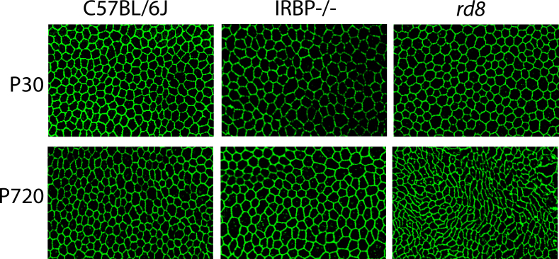
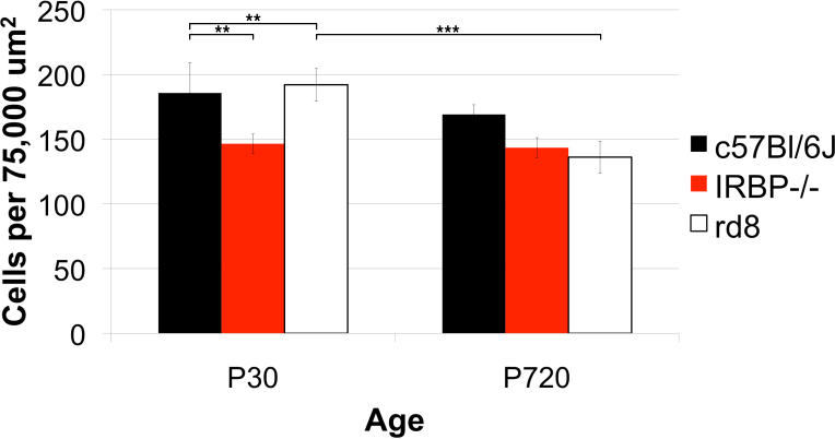
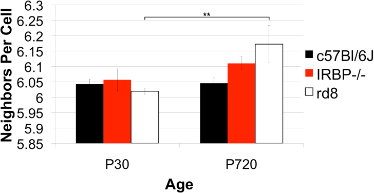
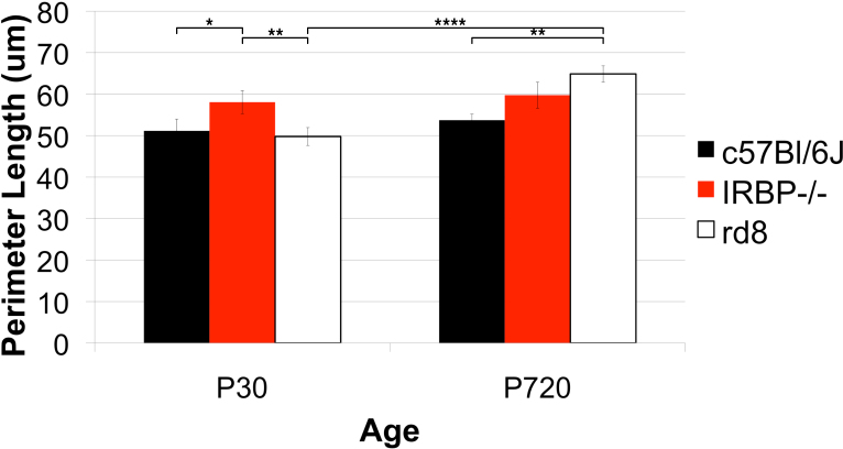
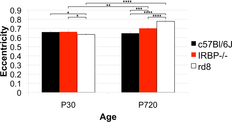
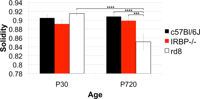
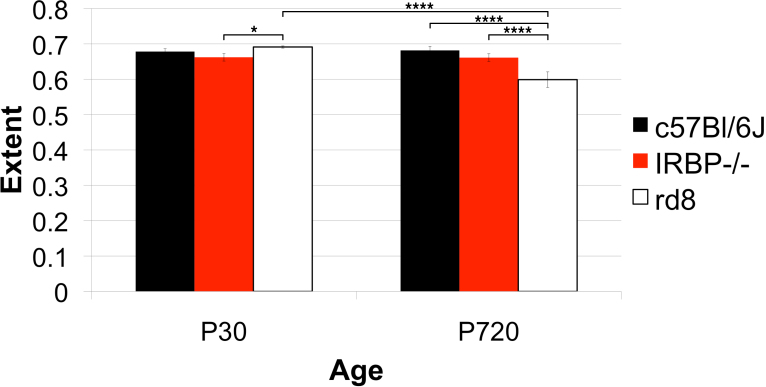
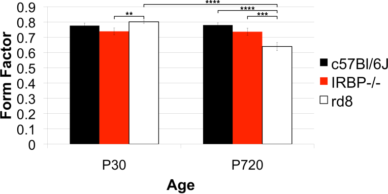
In Figure 13, we compared old versus young and normal versus mutant mouse RPE sheets. By human observation, there were few obvious differences in the RPE sheets of young (P30) mice regardless of the three strains we compared, but at a later age (P720), we found significant, quantitative changes as the mice aged, and as retinal degenerations progressed. These quantitative outcomes are illustrated in Figure 13, Figure 14, Figure 15, Figure 16, Figure 17, Figure 18, Figure 19, and Figure 20. The metrics quantified and calculated in CellProfiler (see Appendix 9 for definitions and examples of the metrics) are given as averages in each respective figure as follows: Figure 14, Density of RPE cells; Figure 15, Number of neighboring cells; Figure 16, Perimeter; Figure 17, Eccentricity; Figure 18, Solidity; Figure 19, Extent; and Figure 20, Form Factor. For most the indicated metrics, wild type (WT, C57BL/6J) and IRBP−/− mouse flatmounts were quantitatively and qualitatively almost identical (at both ages, postnatal day [P]30 and P720); however, the rd8 mutant mice exhibited distinct changes showing on average fewer and larger RPE cells with a less regular appearance (a distorted cell shape) at P720 compared to WT at P720 or to rd8 at P30.
Figure 13.
Qualitative variation in RPE sheets among different strains of mice. Each image represents a 75,000 square micron field of anti-ZO-1 stained RPE from three mouse genotypes, C57Bl/6J (wild type, WT), IRBP−/−, and rd8 at postnatal day (P)30 and P720. A: C57Bl/6J at P30. B: C57Bl/6J at P720. C: IRBP−/− at P30. D: IRBP−/− at P720. E: rd8 at P30. F: rd8 at P720.
Figure 14.
Strain differences in cell density. The density of RPE cells was calculated per 75,000 square micron area. The cell densities of three genotypes, one wild type (WT), C57Bl/6J, and two models of retinal degeneration, IRBP−/− and rd8, were compared at two ages, postnatal days (P)30 and P720. N=4–5 animals for each genotype at P30, and n=3 animals at each genotype at P720. The cell density of IRBP−/− was decreased at P30 compared to WT, but its density remained steady through P720, while that of the WT dropped slightly. The cell density in rd8 was similar to WT at P30, but the rd8 density decreased markedly by P720, while that of the WT remained steady.
Figure 15.
Strain differences in the number of neighboring RPE cells. Three genotypes, one wild type (WT), C57Bl/6J, and two models of retinal degeneration, IRBP−/− and rd8 at postnatal day (P)30 and P720 were compared. The sample sizes were four to five animals for each genotype at P30, and three animals for each genotype at P720. Although no significant differences in number of neighboring cells was present at P30, both the IRBP−/− and the rd8 showed significantly higher average number of neighbors than their WT counterpart at P720. As the IRBP−/− aged from P30 to P720, average number of neighbors does not increase significantly. However, the rd8 showed a significant increase in average number of neighboring RPE cells from P30 to P720. A side is defined by a cell-to-cell contact with a different cell. The total number of sides is equivalent to the number of neighboring cells.
Figure 16.
Strain differences in perimeter length. Three genotypes, one wild type (WT), C57Bl/6J, and two models of retinal degeneration were compared, IRBP−/− and rd8, at two ages, postnatal days 30 and 720. The sample sizes were four to five animals for each genotype at P30 and three animals per genotype at P720. IRBP−/− had a longer perimeter length at P30 and P720 compared to WT. There was no change between P30 and P720 for either IRBP−/− or WT. However, while rd8 did not differ in the average perimeter length of each cell at P30, it was greater at P720 compared to WT.
Figure 17.
Strain differences in eccentricity. Three genotypes, one wild type (WT), C57Bl/6J, and two models of retinal degeneration, IRBP−/− and rd8, at postnatal day (P)30 and P720 were compared. Group sizes were four to five animals for each genotype at P30 and three animals for each genotype at P720. The rd8 was slightly reduced in average eccentricity at P30 compared to WT, but there was no difference in eccentricity between IRBP−/− and WT at P30. As the WT aged, its RPE cells retained the same eccentricity. There was a slight increase in eccentricity in the IRBP−/− between P30 and P720. However, the rd8 showed markedly increased average eccentricity at P720 compared to P30. Additionally, the IRBP−/− was slightly more eccentric than the age-matched WT. There was a large difference between the rd8 and the WT at P720.
Figure 18.
Strain differences in solidity. The solidity of RPE cells in three genotypes, one wild type (WT), C57Bl/6J, and two models of retinal degeneration, IRBP−/− and rd8, at postnatal day (P)30 and P720. Group sizes were four to five animals for each genotype at P30 and three animals at each genotype at P720. At P30, neither the IRBP−/− nor the rd8 differed significantly in cell solidity from the WT. However, at P720, RPE cells of the rd8 were significantly less solid than those of the rd8 at P30 and the WT at P720.
Figure 19.
Strain differences in extent. Three genotypes, one wild type (WT), C57Bl/6J, and two models of retinal degeneration, IRBP−/− and rd8, at postnatal day (P)30 and 720 were compared. Group sizes were four to five animals for each genotype at P30 and three animals for each genotype at P720. The extent in rd8 was slightly larger than in WT. The WT and the IRBP−/− were the same at P30 or P720. However, the rd8 at P720 was significantly smaller than the rd8 at P30 or age-matched WT.
Figure 20.
Strain differences in form factor. Three genotypes, one wild type (WT), C57Bl/6J, and two models of retinal degeneration were compared, IRBP−/− and rd8, at postnatal day (P)30 and P720. Four to five animals for each genotype at P30 and three animals for each genotype at P720 were sampled and compared. At P30, neither the IRBP−/− nor the rd8 differed significantly from the WT. The WT and the IRBP−/− were the same at both P30 and P720. However, the rd8 at P720 had a significantly smaller form factor than rd8 or its age-matched WT did at P30.
Discussion
To our knowledge, RPE cell-shape metrics (quantitatively described by form factor, eccentricity, and other characteristics) are rarely used for RPE sheet analysis [14], and when they are used, only human RPE cells are analyzed. In other epithelial sheet analyses, in particular of the corneal endothelium, only a few parameters—including shape, hexagonality, and cell density—are typically considered. However, many different quantitative metrics have been extensively employed in nonocular tissues, especially the Drosophila wing epithelium.
Advances in the study of the Drosophila wing epithelium [11,12] have recently shed light on subtle but important differences in the geometry of individual cells and the topological arrangements that imply networks of cells [34]. These cell-packing patterns are governed in part by genetics, cell division, growth, force sensing, signaling, and mechanics [34-36]. These changes in size and shape and the emergence of a different epithelial organization during wing development are coordinated [34]. In the present report, we adopted analogous analysis strategies to those used for the Drosophila wing to explore mechanisms governing RPE sheet organization. However, we asked what happens when RPE cells die (both normally and during pathology) instead of when they are born, as was done in the Drosophila wing epithelium investigations. These two processes are quite distinct; loss of RPE cells does not simply involve running the proliferation process backwards through time. After the eye is fully grown, it does not shrink. Extracellular matrices are different in the young, old, and diseased eye, and the tractional forces are different. The remaining RPE cells are expected to increase in size to make up for the loss of another cell (to keep the outer BRB intact). Thus, the loss of RPE cells is expected to have different consequences on the patterning of a damaged RPE sheet compared to the early developing RPE sheet. However, without high-quality images of many RPE cells, studies analogous to those in the Drosophila wing epithelium cannot be conducted on the RPE; hence, we identified the need for the methods that we describe here to obtain suitable images from the mouse RPE for advanced quantitative analyses similar to those carried out on the Drosophila wing [34-36].
Here, we attempted to evaluate RPE sheets based on local organization. Our tools provide the location of each cell center and each vertex in large numbers (tens of thousands of cells) in different geographic regions of the globe. These datasets offer the intriguing possibility of analyzing both local and distant topological interactions, including stretching changes caused by growth or gross distortions caused by drusen [37], geographic atrophic lesions, injury, or bystander damage.
Mathematical modeling and simulations suggest a rationale for the movement and reorganization of the RPE sheet in two dimensions (2D) and 3D based on physical principles [11] after an RPE cell dies. To test these models in vivo, we needed a rapid system to test a large fraction of cells from the whole RPE sheet. As there are so many RPE cells per sheet in an adult mouse eye [18], it was impractical to analyze the shapes of so many without a digital imaging system and software. Here, we detailed such a system, which has proven effective [38,39]. In this study, we validated the system by comparing the resulting cell counts and other statistics from the software to those collected manually. The automated approach produced outcomes that were within the variation among human observers (Figure 11 and Figure 12).
The resulting protocol and software are simple to initiate and use. The critical steps include the following: a) a short fixation time, b) the use of ZO-1 antibodies for mouse and phalloidin for human, c) confocal imaging at high magnification, d) the use of an old version (CS2) of Adobe Photoshop to photomerge images, and e) collection of accurately overlapped images from an automated stage. The software is open-source CellProfiler, which is robust and well supported. As test cases, we applied the optimized RPE sheet preparation and software protocols to examine two retinal degeneration mutations (rd8 and IRBP−/−), asking whether collateral damage in the adjacent RPE sheets occurred in either model.
The rd8 mutation [40,41] is in the crb1 gene, and this plays a role in establishing and maintaining apicobasal polarity in these epithelial cells. The loss of Crb1 breaches the outer limiting membrane in the rd8 mouse [40]. We might anticipate that rd8 would cause problems in the RPE sheet as a bystander effect. Rd8 is commonly found the C57BL/6N strains of mice, which are frequently used in transgenic and knockout mouse technology. Many strains of mice bear the rd8 lesion. Although the rd1 and rd10 lesions cause far more rapid and intense damage compared to rd8, it may be that many mouse lines have visual disorders solely because of contamination of the lines with rd8, which arose in “N” lines in the early 1950s, but was not noticed as an ongoing problem until 2012 [42]. In our analyses, rd8 caused extensive damage to the RPE sheet only at an old age.
The IRBP−/− had no obvious deleterious effect on the RPE: It did not appear that the RPE sheet was defective in patterning or tiling, regardless of local or global patterns (or any other metrics), of young or old, whether the sheet was examined before PhR cell death or well after much of the outer nuclear layer (ONL) was lost when comparing the IRBP−/− to WT mice. This may suggest a different cell death process [43] in IRBP−/− compared to death in other retinal degenerations such as in rd10 [31,39]—one that causes little bystander damage to the RPE, and that is quite different from that noted in the rd8 mutation here. That is, the loss of IRBP has different effects on RPE maintenance, with little or no particular impact on it. This is also different from the quite obvious and substantial loss of the ONL of the neural retina caused when no IRBP is present [44,45].
Future improvements
Nuclei
Information on the nucleated state (one nucleus, or more than one nucleus per RPE cell) compared to the size, shape, and location of each cell is needed. An apical-basal alignment of the long axis of nuclei among different RPE cells might normally be expected, as the RPE cells are quite regular. A distortion in the orientation of nuclei might indicate a basis of pathology during degeneration of the RPE sheet. A current difficulty is to correctly match the tight junctions of a given cell with its nucleus or nuclei, which are on a distinctly lower Z-axis plane, more basal from the tight junctions. A second complication is to ensure that nuclei in the choroid underlying the RPE are not mistakenly analyzed. When RPE cells are stretched thin, reducing melanosome density, there can be show-through of the nuclei from the underlying capillaries. While it might seem that careful focusing of the confocal microscope on the planes that overlie the choroid would solve this problem, the brightness of choroidal nuclei stained with efficient fluorophores is great, leading to a potential confounding effect of these choroidal nuclei. That is, they may appear to be nuclei of RPE cells. One solution [18] is to remove the underlying choroid from the RPE sheet (a tedious process). Another is to image at higher magnification and use thinner stacks or no stacks with a smaller confocal pinhole, so that the choroid is never imaged. The latter approach would require only some comparatively minor adjustments to the current software for processing and analysis of the resulting higher power images.
More time points
In general, we found distinct differences in some metrics of cell shape and size depending on location in the globe and age [31], and as illustrated in Figure 13, Figure 14, Figure 15, Figure 16, Figure 17, Figure 18, Figure 19, and Figure 20 in the present work. More time points at intermediate and older ages in WT and mutant strains of mice are expected to clarify effects due to age versus pathology and disease of the RPE cell.
More genotypes
We know that there will be distinctive phenotypic and quantitative differences based on precise DNA sequence changes [31]. This is borne out in another strain that we report here, the rd8 mutation. We need more different mutant genotypes to be tested to distinguish one disease from the next.
Noninvasive images
Human RPE soon may be routinely imaged noninvasively [46-49]. The image processing and analysis software described here, with minor modification, ought to be directly applicable to images from human, mouse, and other species in aging and in disease states, whether imaged in living tissue, or as illustrated here, after death.
Spatial point pattern analysis
Qualitative analyses suggest that RPE cells in different zones may interact differently due to the differing shape and size of each cell, and due to different types of mechanical, chemical, or pathological stress in different locations of the sheet. Analogous regular arrangements of cells in the inner retina are well known [50-53] and reflect physiological signaling during development of the inner retina such that dendritic fields of homotypic cells do not overlap. Determination of the spatial point patterns of each RPE cell with others as regular, clustered, normally distributed, random, or other pattern will help us understand the function of the RPE sheet. Adequate statistical packages for these analyses have already been developed, for example, the Spatstat package for R [54]. We have begun to use these point pattern analysis tools on our existing databases of RPE sheets.
Automation improvements
Preliminary studies suggest that we can automate the selection of RPE rectangles that are artifact-free using pattern based statistical analysis, so that more of the RPE sheet can be analyzed per flatmount.
Summary of key points to ensure the success of the flatmounting technique
1. Keep it simple. The less done, the fewer errors are made, the less damage is done, the less time it takes, and the more reliable the resulting data will be. There is no need to remove the sclera or choroid from the mouse eye.
2. Make the minimum number of cuts to flatten the sheet for the purpose at hand. Four cuts were optimal in our work. Additional shallow relief cuts can be made along the outer edge as shown in the movie (Figure 1) at the outside edge of each flap.
3. Be extremely careful not to accidentally score the RPE during any manipulation.
4. Do not over fix. Less is better (10 min is ideal in our hands), but then process the tissue, and conduct the imaging relatively quickly, preferably the day after the mounting medium has solidified.
5. Do not overstain. Use the lowest possible titer of the primary and secondary antibodies to keep the cell borders clean and to reflect specific staining with ZO-1. The lower the background inside the cell, the better. Investigators may need to test several sources and lots of ZO-1 antibodies or use a different cell border marker.
6. In terms of imaging, we obtained reliable image quality and assembly of photomerged images if we used a confocal microscope with an automated stage that moves in a uniform pattern and overlaps one image with the next by 10%.
7. Pay close attention to sampling locations. Normal RPE cells at the outer edge near the ciliary body have different shapes (a more relaxed and shield-like appearance with a less-regular hexagonal shape; cf., [39,55]) compared to the more central and posterior sheet (more regular polygons). Sample from all different rings and quadrants of the bull’s-eye target.
Acknowledgments
This work was supported by the National Eye Institute (R01EY016470 (JN), R01EY021592 (JN), R01EY014026 (JHB), P30EY006360, an unrestricted grant to the Department of Ophthalmology at Emory University from Research to Prevent Blindness, Inc., and the Abraham and Phyllis Katz Foundation (JHB).
Appendix 1. JavaScript for ImageJ to convert Nikon IDS format to BMP.
To access the data, click or select the words “Appendix 1.” The appendices contain Photoshop Actions, Matlab, Perl scripts, and CellProfiler pipelines. If used with the indicated versions of these software packages, there should be no major difficulties in installing the scripts and using this system for RPE sheet analyses.
Appendix 2. A Photoshop CS3 “Action” entitled ProcessImage
To access the data, click or select the words “Appendix 2.”
Appendix 3. A grid (Figure 7) made of concentric circles, starting 400 microns from the optic nerve, with concentric circles placed 320 microns apart, was made 30% opaque
To access the data, click or select the words “Appendix 3.”
Appendix 4. A Photoshop CS3 “Action” entitled SetSelection.
To access the data, click or select the words “Appendix 4.”
Appendix 5. Photoshop CS3 scripts called “grab_selection_20N, grab_selection_20S, grab_selection_20E, or grab_selection_20W .” A different script is used depending on which quadrant is being processed.
To access the data, click or select the words “Appendix 5.”
Appendix 6. A CellProfiler pipeline “cp10-mouse-rpe.cp”
To access the data, click or select the words “Appendix 6.”
Appendix 7. A shell script called “bash_analysis”
To access the data, click or select the words “Appendix 7.”
Appendix 8: A CellProfiler v2.1.1 pipeline, “cp211-mouse-RPE.cpea”.
To access the data, click or select the words “Appendix 8.”
Appendix 9. A table of object size and shape measurements used in this study.
To access the data, click or select the words “Appendix 9.” CellProfiler collects and calculates many parameters that describe object size and shape. In most cases, these measurements include a statistic that describes the variation of the metric expressed as a standard deviation. The CellProfiler documentation describes each parameter or metric fully, and the reader is urged to consult this freely available documentation. A table of metrics here is a set that we used for analysis in this study, but the reader should find it useful to consult the CellProfiler documentation for other worthy metrics that might apply to different experimental needs for measurement of intensity and texture of each cell.
References
- 1.Strauss O. The retinal pigment epithelium in visual function. Physiol Rev. 2005;85:845–81. doi: 10.1152/physrev.00021.2004. [DOI] [PubMed] [Google Scholar]
- 2.Rizzolo LJ, Peng S, Luo Y, Xiao W. Integration of tight junctions and claudins with the barrier functions of the retinal pigment epithelium. Prog Retin Eye Res. 2011;30:296–323. doi: 10.1016/j.preteyeres.2011.06.002. [DOI] [PubMed] [Google Scholar]
- 3.Peng S, Rao VS, Adelman RA, Rizzolo LJ. Claudin-19 and the barrier properties of the human retinal pigment epithelium. Invest Ophthalmol Vis Sci. 2010 doi: 10.1167/iovs.10-5984. [DOI] [PMC free article] [PubMed] [Google Scholar]
- 4.Williams CD, Rizzolo LJ. Remodeling of junctional complexes during the development of the outer blood-retinal barrier. Anat Rec. 1997;249:380–8. doi: 10.1002/(SICI)1097-0185(199711)249:3<380::AID-AR9>3.0.CO;2-Y. [DOI] [PubMed] [Google Scholar]
- 5.Kaur C Foulds W, Ling E. Blood–retinal barrier in hypoxic ischaemic conditions: Basic concepts, clinical features and management. Prog Retin Eye Res. 2008;27:622–47. doi: 10.1016/j.preteyeres.2008.09.003. [DOI] [PubMed] [Google Scholar]
- 6.Simó R, Villarroel M, Corraliza L, Hernández C, García-Ramírez M. The retinal pigment epithelium: something more than a constituent of the blood-retinal barrier–implications for the pathogenesis of diabetic retinopathy. J Biomed Biotechnol. 2010;2010:190724. doi: 10.1155/2010/190724. [DOI] [PMC free article] [PubMed] [Google Scholar]
- 7.Bastiaans J, van Meurs JC, van Holten-Neelen C, Nagtzaam NMA, van Hagen PM, Chambers RC, Hooijkaas H, Dik WA. Thrombin induces epithelial-mesenchymal transition and collagen production by retinal pigment epithelial cells via autocrine PDGF-receptor signaling. Invets Ophthal Visual Science. 2013;54:8306–14. doi: 10.1167/iovs.13-12383. [DOI] [PubMed] [Google Scholar]
- 8.Kim JH, Lee S-J, Kim K-W, Yu YS, Kim JH. Oxidized low density lipoprotein-induced senescence of retinal pigment epithelial cells is followed by outer blood-retinal barrier dysfunction. Int J Biochem Cell Biol. 2012;44:808–14. doi: 10.1016/j.biocel.2012.02.005. [DOI] [PubMed] [Google Scholar]
- 9.Nagai H, Kalnins VI. Normally occurring loss of single cells and repair of resulting defects in retinal pigment epithelium in situ. Exp Eye Res. 1996;62:55–61. doi: 10.1006/exer.1996.0007. [DOI] [PubMed] [Google Scholar]
- 10.Kalnins VI, Sandig M, Hergott GJ, Nagai H. Microfilament organization and wound repair in retinal pigment epithelium. Biochem Cell Biol. 1995;73:709–22. doi: 10.1139/o95-079. [DOI] [PubMed] [Google Scholar]
- 11.Farhadifar R, Röper J-C, Aigouy B, Eaton S, Jülicher F. The influence of cell mechanics, cell-cell interactions, and proliferation on epithelial packing. Curr Biol. 2007;17:2095–104. doi: 10.1016/j.cub.2007.11.049. [DOI] [PubMed] [Google Scholar]
- 12.Bardet P-L, Guirao B, Paoletti C, Serman F, Léopold V, Bosveld F, Goya Y, Mirouse V, Graner F, Bellaïche Y. PTEN controls junction lengthening and stability during cell rearrangement in epithelial tissue. Dev Cell. 2013;25:534–46. doi: 10.1016/j.devcel.2013.04.020. [DOI] [PubMed] [Google Scholar]
- 13.Guillot C, Lecuit T. Mechanics of epithelial tissue homeostasis and morphogenesis. Science. 2013;340:1185–9. doi: 10.1126/science.1235249. [DOI] [PubMed] [Google Scholar]
- 14.Watzke RC, Soldevilla JD, Trune DR. Morphometric analysis of human retinal pigment epithelium: correlation with age and location. Curr Eye Res. 1993;12:133–42. doi: 10.3109/02713689308999481. [DOI] [PubMed] [Google Scholar]
- 15.Harman AM, Fleming PA, Hoskins RV, Moore SR. Development and aging of cell topography in the human retinal pigment epithelium. Invest Opthal Vis Sci. 1997;38:2016–26. [PubMed] [Google Scholar]
- 16.Snodderly DM, Sandstrom MM, Leung IY-F, Zucker CL, Neuringer M. Retinal pigment epithelial cell distribution in central retina of rhesus monkeys. Invest Ophthalmol Vis Sci. 2002;43:2815–8. [PubMed] [Google Scholar]
- 17.Bodenstein L, Sidman RL. Growth and development of the mouse retinal pigment epithelium. II. Cell patterning in experimental chimaeras and mosaics. Dev Biol. 1987;121:205–19. doi: 10.1016/0012-1606(87)90153-9. [DOI] [PubMed] [Google Scholar]
- 18.Bodenstein L, Sidman RL. Growth and development of the mouse retinal pigment epithelium. I. Cell and tissue morphometrics and topography of mitotic activity. Dev Biol. 1987;121:192–204. doi: 10.1016/0012-1606(87)90152-7. [DOI] [PubMed] [Google Scholar]
- 19.Ding J-D, Johnson LV, Herrmann R, Farsiu S, Smith SG, Groelle M, Mace BE, Sullivan P, Jamison JA, Kelly U, Harrabi O, Bollini SS, Dilley J, Kobayashi D, Kuang B, Li W, Pons J, Lin JC, Bowes Rickman C. Anti-amyloid therapy protects against retinal pigmented epithelium damage and vision loss in a model of age-related macular degeneration. Proc Natl Acad Sci USA. 2011;108:E279–87. doi: 10.1073/pnas.1100901108. [DOI] [PMC free article] [PubMed] [Google Scholar]
- 20.Wang B-G, Eitner A, Lindenau J, Halbhuber K-J. High-resolution two-photon excitation microscopy of ocular tissues in porcine eye. Lasers Surg Med. 2008;40:247–56. doi: 10.1002/lsm.20628. [DOI] [PubMed] [Google Scholar]
- 21.Konari K, Sawada N, Zhong Y, Isomura H, Nakagawa T, Mori M. Development of the blood-retinal barrier in vitro: formation of tight junctions as revealed by occludin and ZO-1 correlates with the barrier function of chick retinal pigment epithelial cells. Exp Eye Res. 1995;61:99–108. doi: 10.1016/s0014-4835(95)80063-8. [DOI] [PubMed] [Google Scholar]
- 22.Frambach DA, Misfeldt DS. Furosemide-sensitive Cl transport in embryonic chicken retinal pigment epithelium. Am J Physiol. 1983;244:F679–85. doi: 10.1152/ajprenal.1983.244.6.F679. [DOI] [PubMed] [Google Scholar]
- 23.Ban Y, Rizzolo LJ. A culture model of development reveals multiple properties of RPE tight junctions. Mol Vis. 1997;3:18. [PubMed] [Google Scholar]
- 24.Maminishkis A, Miller SS. Experimental models for study of retinal pigment epithelial physiology and pathophysiology. J Vis Exp. 2010;45:45. doi: 10.3791/2032. [DOI] [PMC free article] [PubMed] [Google Scholar]
- 25.Claybon A, Bishop AJR. Dissection of a mouse eye for a whole mount of the retinal pigment epithelium. J Vis Exp. 2011;48:48. doi: 10.3791/2563. [DOI] [PMC free article] [PubMed] [Google Scholar]
- 26.Carpenter AE. Extracting rich information from images. Methods Mol Biol. 2009;486:193–211. doi: 10.1007/978-1-60327-545-3_14. [DOI] [PubMed] [Google Scholar]
- 27.Logan DJ, Carpenter AE. Screening cellular feature measurements for image-based assay development. J Biomol Screen. 2010;15:840–6. doi: 10.1177/1087057110370895. [DOI] [PMC free article] [PubMed] [Google Scholar]
- 28.Jones TR, Carpenter AE, Lamprecht MR, Moffat J, Silver SJ, Grenier JK, Castoreno AB, Eggert US, Root DE, Golland P, Sabatini DM. Scoring diverse cellular morphologies in image-based screens with iterative feedback and machine learning. Proc Natl Acad Sci USA. 2009;106:1826–31. doi: 10.1073/pnas.0808843106. [DOI] [PMC free article] [PubMed] [Google Scholar]
- 29.Kamentsky L, Jones TR, Fraser A, Bray M-A, Logan DJ, Madden KL, Ljosa V, Rueden C, Eliceiri KW, Carpenter AE. Improved structure, function and compatibility for CellProfiler: modular high-throughput image analysis software. Bioinformatics. 2011;27:1179–80. doi: 10.1093/bioinformatics/btr095. [DOI] [PMC free article] [PubMed] [Google Scholar]
- 30.Bray M-A, Fraser AN, Hasaka TP, Carpenter AE. Workflow and metrics for image quality control in large-scale high-content screens. J Biomol Screen. 2012;17:266–74. doi: 10.1177/1087057111420292. [DOI] [PMC free article] [PubMed] [Google Scholar]
- 31.SJiang Y, Qi X, Chrenek MA, Gardner C, Boatright JH, Grossniklaus HE, Nickerson JM.Functional principal component analysis reveals discriminating categories of retinal pigment epithelial morphology in mice Invest Opthal Visual Science 2013547274–83. [DOI] [PMC free article] [PubMed] [Google Scholar]
- 32.Johnson CJ, Berglin L, Chrenek MA, Redmond TM, Boatright JH, Nickerson JM. Technical brief: subretinal injection and electroporation into adult mouse eyes. Mol Vis. 2008;14:2211–26. [PMC free article] [PubMed] [Google Scholar]
- 33.Carpenter AE, Jones TR, Lamprecht MR, Clarke C, Kang IH, Friman O, Guertin DA, Chang JH, Lindquist RA, Moffat J, Golland P, Sabatini DM. CellProfiler: image analysis software for identifying and quantifying cell phenotypes. Genome Biol. 2006;7:R100. doi: 10.1186/gb-2006-7-10-r100. [DOI] [PMC free article] [PubMed] [Google Scholar]
- 34.Sánchez-Gutiérrez D, Sáez A, Pascual A, Escudero LM. Topological progression in proliferating epithelia is driven by a unique variation in polygon distribution. PLoS ONE. 2013;8:e79227. doi: 10.1371/journal.pone.0079227. [DOI] [PMC free article] [PubMed] [Google Scholar]
- 35.Classen A-K, Anderson KI, Marois E, Eaton S. Hexagonal packing of Drosophila wing epithelial cells by the planar cell polarity pathway. Dev Cell. 2005;9:805–17. doi: 10.1016/j.devcel.2005.10.016. [DOI] [PubMed] [Google Scholar]
- 36.Aegerter-Wilmsen T, Heimlicher MB, Smith AC, de Reuille PB, Smith RS, Aegerter CM, Basler K. Integrating force-sensing and signaling pathways in a model for the regulation of wing imaginal disc size. Development. 2012;139:3221–31. doi: 10.1242/dev.082800. [DOI] [PubMed] [Google Scholar]
- 37.Al-Hussaini H, Schneiders M, Lundh P, Jeffery G. Drusen are associated with local and distant disruptions to human retinal pigment epithelium cells. Exp Eye Res. 2009;88:610–2. doi: 10.1016/j.exer.2008.09.021. [DOI] [PubMed] [Google Scholar]
- 38.Jiang Y, Qi X, Chrenek MA, Gardner C, Dalal N, Boatright JH, Grossniklaus HE, Nickerson JM. Analysis of Mouse RPE Sheet Morphology Gives Discriminatory Categories. Adv Exp Med Biol. 2014;•••:601–607. doi: 10.1007/978-1-4614-3209-8_76. [DOI] [PMC free article] [PubMed] [Google Scholar]
- 39.Chrenek MA, Dalal N, Gardner C, Grossniklaus H, Jiang Y, Boatright JH, Nickerson JM. Analysis of the RPE sheet in the rd10 retinal degeneration model. Adv Exp Med Biol. 2012;723:641–7. doi: 10.1007/978-1-4614-0631-0_81. [DOI] [PMC free article] [PubMed] [Google Scholar]
- 40.den Hollander AIA, ten Brink JBJ, de Kok YJY, van Soest SS, van den Born LIL, van Driel MAM, van de Pol DJD, Payne AMA, Bhattacharya SSS, Kellner UU, Hoyng CBC, Westerveld AA, Brunner HGH, Bleeker-Wagemakers EME, Deutman AFA, Heckenlively JRJ, Cremers FPF, Bergen AAA. Mutations in a human homologue of Drosophila crumbs cause retinitis pigmentosa (RP12). Nat Genet. 1999;23:217–21. doi: 10.1038/13848. [DOI] [PubMed] [Google Scholar]
- 41.Richard M, Roepman R, Aartsen WM, van Rossum AGSH, den Hollander AI, Knust E, Wijnholds J, Cremers FPM. Towards understanding CRUMBS function in retinal dystrophies. Hum Mol Genet. 2006;15(Spec No 2):R235–43. doi: 10.1093/hmg/ddl195. [DOI] [PubMed] [Google Scholar]
- 42.Mattapallil MJ, Wawrousek EF, Chan C-C, Zhao H, Roychoudhury J, Ferguson TA, Caspi RR. The rd8 mutation of the Crb1 gene is present in vendor lines of C57BL/6N mice and embryonic stem cells, and confounds ocular induced mutant phenotypes. Investigative Ophthalmology & Visual Science 2012. [DOI] [PMC free article] [PubMed] [Google Scholar]
- 43.Sato K, Li S, Gordon WC, He J, Liou GI, Hill JM, Travis GH, Bazan NG, Jin M. Receptor interacting protein kinase-mediated necrosis contributes to cone and rod photoreceptor degeneration in the retina lacking interphotoreceptor retinoid-binding protein. J Neurosci. 2013;33:17458–68. doi: 10.1523/JNEUROSCI.1380-13.2013. [DOI] [PMC free article] [PubMed] [Google Scholar]
- 44.Wisard J, Faulkner A, Chrenek MA, Waxweiler T, Waxweiler W, Donmoyer C, Liou GI, Craft C, Schmid GF, Boatright JH, Pardue MT, Nickerson JM. Exaggerated eye growth in IRBP deficient mice in early development. Invest Ophthalmol Vis Sci. 2011;52:5804–11. doi: 10.1167/iovs.10-7129. [DOI] [PMC free article] [PubMed] [Google Scholar]
- 45.Ripps H, Peachey NS, Xu X, Nozell SE, Smith SB, Liou GI. The rhodopsin cycle is preserved in IRBP “knockout” mice despite abnormalities in retinal structure and function. Vis Neurosci. 2000;17:97–105. doi: 10.1017/s095252380017110x. [DOI] [PubMed] [Google Scholar]
- 46.Roorda A, Zhang Y, Duncan JL. High-resolution in vivo imaging of the RPE mosaic in eyes with retinal disease. Invest Ophthalmol Vis Sci. 2007;48:2297–303. doi: 10.1167/iovs.06-1450. [DOI] [PubMed] [Google Scholar]
- 47.Rossi EA, Rangel-Fonseca P, Parkins K, Fischer W, Latchney LR, Folwell MA, Williams DR, Dubra A, Chung MM. In vivo imaging of retinal pigment epithelium cells in age related macular degeneration. Biomed Opt Express. 2013;4:2527–39. doi: 10.1364/BOE.4.002527. [DOI] [PMC free article] [PubMed] [Google Scholar]
- 48.Morgan JI, Dubra A, Wolfe R, Merigan WH, Williams DR. In vivo autofluorescence imaging of the human and macaque retinal pigment epithelial cell mosaic. Invest Ophthalmol Vis Sci. 2009;50:1350–9. doi: 10.1167/iovs.08-2618. [DOI] [PMC free article] [PubMed] [Google Scholar]
- 49.Scoles D, Sulai YN, Dubra A. In vivo dark-field imaging of the retinal pigment epithelium cell mosaic. Biomed Opt Express. 2013;4:1710–23. doi: 10.1364/BOE.4.001710. [DOI] [PMC free article] [PubMed] [Google Scholar]
- 50.Reese BE. Development of the retina and optic pathway. Vision Res. 2011;51:613–32. doi: 10.1016/j.visres.2010.07.010. [DOI] [PMC free article] [PubMed] [Google Scholar]
- 51.Diggle PJ. Displaced amacrine cells in the retina of a rabbit: analysis of a bivariate spatial point pattern. J Neurosci Methods. 1986;18:115–25. doi: 10.1016/0165-0270(86)90115-9. [DOI] [PubMed] [Google Scholar]
- 52.Fuerst PG, Koizumi A, Masland RH, Burgess RW. Neurite arborization and mosaic spacing in the mouse retina require DSCAM. Nature. 2008;451:470–4. doi: 10.1038/nature06514. [DOI] [PMC free article] [PubMed] [Google Scholar]
- 53.Cameron DA, Carney LH. Cellular patterns in the inner retina of adult zebrafish: quantitative analyses and a computational model of their formation. J Comp Neurol. 2004;471:11–25. doi: 10.1002/cne.11040. [DOI] [PubMed] [Google Scholar]
- 54.Baddeley A, Turner R. Package ‘spatstat’. Documentation 2014:1–1255. [Google Scholar]
- 55.Kokkinopoulos I, Shahabi G, Colman A, Jeffery G. Mature peripheral RPE cells have an intrinsic capacity to proliferate; a potential regulatory mechanism for age-related cell loss. PLoS ONE. 2011;6:e18921. doi: 10.1371/journal.pone.0018921. [DOI] [PMC free article] [PubMed] [Google Scholar]


