Abstract
Instrumented gait analysis based on optoelectronic systems is an expensive technique used to objectively measure the human movement features and it is generally considered as the gold standard. Opto-electronic plethysmography (OEP) is a particular motion analysis system able to: (i) determine chest wall kinematic via the evaluation of marker displacements placed on the thorax and (ii) compute respiratory volumes during breathing.
The aim of this work is to describe the performances of a custom made, bio-inspired, mechatronic chest wall simulator (CWS), specifically designed to assess the metrological performances of the OEP system. The design of the simulator is based on the chest wall kinematic analysis of three healthy subjects previously determined.
Two sets of experiments were carried out: (i) to investigate the CWS dynamic response using different target displacements (1 - 12 mm), and (ii) to assess the CWS accuracy and precision in simulating quite breathing, covering the physiological range of respiratory frequency and tidal volume.
Results show that the CWS allows simulating respiratory frequency up to ~ 60 bpm. The difference between the actual displacement and the set one is always < 9 μm. The precision error, expressed as the ratio between measurement uncertainty and the actual displacement, is lower than 0.32 %.
The observed good performances permit to consider the CWS prototype feasible to be employed for assessing the performances of OEP system in periodical validation routines.
Keywords: Breathing pattern, chest wall kinematic, chest wall simulator, metrological assessment, motion analysis, opto-electronic plethysmography, respiratory monitoring.
1. INTRODUCTION
Motion analysis systems are used to measure human movements. In the last decade, a growing interest on opto-electronic systems has been established [1, 2]. Differently from the other technologies [3-7], they are based on the recording of the light reflected back by markers illuminated by light sources (typically IR) or directly collected by specific transducers to measure and study human complex movements for different clinical fields, e.g. analysis of general physical activities [8-10], gait analysis [11-13], posture and trunk movements [14], upper limbs movement [15], respiratory biomechanics [16-22].
The first study aiming at calculating three-dimensional chest wall volume changes dates back to 1994 [23], where authors developed the first motion analysis systems for assessing breathing mechanics, implementing an algorithm on the ELITE plus OR system. The first version of the developed system was composed of 4 cameras positioned in the workspace and 32 hemispherical passive markers placed along vertical and horizontal lines on the individual’s chest wall. Volume was estimated through a geometrical construction and a model based on 54 tetrahedrons. The lung volume was evaluated through the ELITE system and verified by spirometry test: a good correlation with spirometric measurements has been observed with a maximum percentage error of 21.3 % in BTPS1 condition [23]. Two years later, Cala et al. [24] improved the accuracy of breathing volume measurements by means of 86 markers (i.e., percentage measurement error ranges between 2 % and 3.5 %) and developed a biomechanical model separating the chest wall into 3 compartments: the upper rib cage, the lower rib cage and the abdomen. In 1999, Gorini et al. [25] proposed a 89 markers protocol for lung volume measurements.
In 2000 Aliverti et al. [26] introduced Opto-electronic Plethysmography (OEP) as result of technologic improvement of ELITE system. Since that milestone, OEP has been used to investigate respiratory pattern parameters [27-29], asynchronies inside chest wall, in respiratory rehabilitation [29-31], and to characterize different respiratory strategies and muscle diseases, such as COPD [27, 32]. Despite the large number of clinical investigations [33], there is still a lack in literature regarding the accuracy, repeatability and other metrological characteristics of OEP systems: we found only two works [34, 35] that aim to assess the reliability, accuracy and precision of the OEP volume measurements, both in static and dynamic conditions. In particular, Bastianini et al. [34] developed an electromechanical system using a DC-precision actuator and a single spherical marker fixed at the end of the motor shaft: by means of that device the discrimination threshold of the OEP system was assessed, as well as the accuracy in small linear displacements. Moreover’- the study examined the effect of the number of cameras (i.e., 2, 4, 6), and of the marker size (spherical 6 and 12 mm diameter) on the properties above. Results showed a 30 μm discrimination threshold and a significant improvement of OEP accuracy with the increase in number of cameras (percentage error decreases from 17% to 10% increasing camera from 2 to 4), for marker of small diameter (i.e. 6 mm). The second study [35] described a dynamic volumetric simulator, designed and assembled to reproduce human thorax movements during breathing: it was controlled to assess volume measurements depending on volume variations computed by a custom algorithm. Results showed that OEP percentage measurement error on tidal volume ranges from 9 % to 20 % and does not depend on thorax displacement’s magnitude.
Nevertheless, an imperfect panel’s synchronization and low repeatability during movements affected the above-described device. Complex motion control system composed by external motion control units, a dedicated host-pc running a LabVIEWTM application, as well as a number of dedicated wiring, introduced motion control issues. Furthermore dimensions of the entire simulator were nearly 3 times higher than calibration workspace.
To the best of our knowledge, no other kinds of volumetric simulators able to provide human chest wall movements covering the whole physiological range of values have been described.
Nowadays, only simulators of the rib cage so-called human mannequin used as training medical procedures, have been developed [36-38]. However, these systems are not able to perform specific chest-wall movements and to simulate kinematics of human chest wall.
In order to fill up the lack of devices, the present work focuses on the design and development of a custom made chest wall simulator (CWS). Cost effective and efficient motor control strategy and apparatus, low dimensions and weight features were considered during the CWS design. Experiments were carried out simulating tidal volume and breathing frequency values in the whole range of physiological interest in order to evaluate CWS performances in both static and dynamic conditions.
2. THEORETICAL BACKGROUND AND CWS DESIGN
2.1. Opto-electronic Plethysmography
The OEP system allows measurement of the chest wall change in volume during breathing, by modeling the thoraco-abdominal surface [26]: three-dimensional position and displacements of each chest wall element are measured by a Motion Analyzer that tracks passive IR-reflective markers, placed on the patient’s skin with a bio-adhesive hypoallergenic tape [39]. The Motion Analyzer is embedded with some specific TV cameras, operating at 60 Hz.
The OEP determines the three-dimensional coordinates of each marker by means of trademarked software (Motion Analyzer, BTS Bioengineering Corp. that is able to reconstruct spatial coordinates after computing the two-dimensional coordinates of a single marker acquired by at least 2 cameras.
In a reference coordinate system, an elementary surface can be obtained starting from connecting each triplet of markers to form a triangle [39, 40]. Therefore a closed surface can be achieved from a triangle mesh of the elementary surfaces above and its volume can be calculated using the Gauss theorem, as widely reported in [24].
This procedure allows the computation of the volume enclosed by the thoraco-abdominal surface [41], approximated by a closed triangle mesh, where vertices correspond to markers positions.
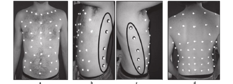
The most commonly used set up for the acquisition both in the standing and sitting position [42-44] consists of 89 markers: seven horizontal and five vertical lines (Fig. 1a, 1d), two medium-axillary (Fig. 1b, 1c), and seven extra markers arranged in anatomical structures between the sternal notch and the clavicles to the level of the anterior superior iliac crest, being 37 anterior (Fig. 1a), 42 posterior (Fig. 1d) and 10 lateral (Fig. 1b, 1c) markers.
Fig. (1).
Opto-electronic plethysmography: 89 marker setup as in [41, 43]. (a) 37 anterior markers, (b) 5 lateral markers (left) (c) 5 lateral markers (right) (d) 42 posterior markers.
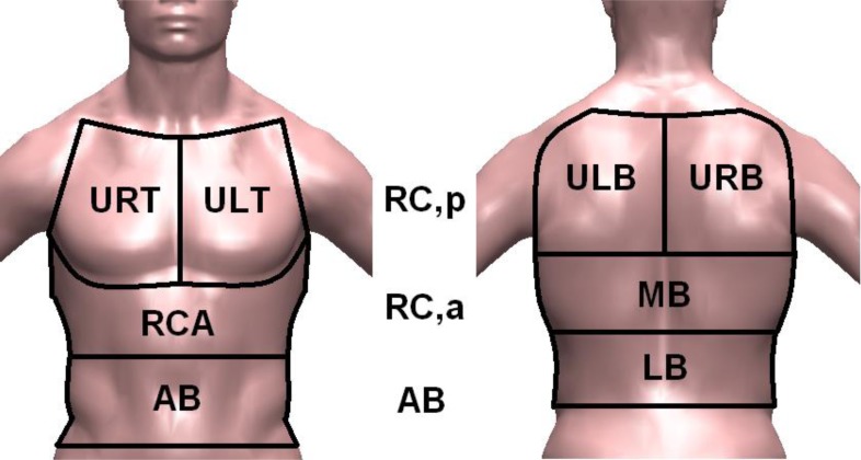
The chest wall was modeled as 3 different compartments: pulmonary rib cage – RC,p – (the part modeled as the rib cage opposed to the lung), abdominal rib cage – RC,a – (the part modeled as the rib cage opposed to the diaphragm), and abdomen – AB –. Abdominal volume change was defined as the volume swept by the abdominal wall, as described in [44] while the total chest wall volume is calculated as the sum of VRC,p, VRC,a, and VAB [40].
2.2. Bio-Inspired Mechatronic Chest Wall Simulator (CWS)
A mechatronic chest wall simulator (CWS) was designed and developed to achieve repeatable dynamic movements, being similar to an adult human chest wall in terms of dimensions, morphological features and kinematics behaviors.
The design was based on anthropometric measurements of thoracic wall [45], in order to choice dimensions as similar as possible to the human thorax (e.g., waist circumference around 1 m). Moreover, three consenting healthy voluntaries selected within the authors (ES, CM, SS) (3 male; heights 1.72, 1.68 and 1.79 m, weights 70, 64 and 80 kg) underwent OEP in order to study human chest wall kinematics and each marker trajectory during the time. Inclusion criteria were: healthy and robust physique previously certified, no history signs of psycho-physical alterations and absence of any kind of breathlessness. Eligible healthy subjects were evaluated by a multidisciplinary team composed by physiotherapists and medical doctors.
2.2.1. Mechanical Design
Mechanical design of the CWS was led by measurements of chest wall movements. In particular, three healthy subjects were enrolled for exam with the OEP above: trajectories of 89 markers have been recorded during quiet breathing in supine position. Starting from marker positions, speed (s, Eq. 1) and acceleration (a, Eq. 2) of each marker were calculated:
| (1) |
| (2) |
where p represents the position in one direction (X, Y, Z), n is the frame number, f is the marker number (ranging from 1 to 89) and t is the time. An N-Point Moving Average filter was used to smooth data. Then, the module of the displacement, speed and acceleration values were calculated. Starting from modules, maximum and minimum values of position, speed and acceleration were obtained considering all the markers and the three patients, in order to know the movement features of each marker during the breathing. Results are showed in Table 1.
Table 1.
Maximum and minimum markers displacement, speed and acceleration data during quiet breathing (mean ± standard deviation).
| MAX | MIN | |
|---|---|---|
| Displacement (mm) | 20 ± 2 | 0.7 ± 0.3 |
| Speed (mm/s) | 20 ± 2 | 0.4 ± 0.1 |
| Acceleration (mm/s2) | 60 ± 1 | 0.5 ± 0.2 |
For each marker the displacement was calculated from trajectories acquired in a three space reference coordinate system: markers trajectories were processed and compared with each other by an ad hoc developed algorithm on 3D image data acquired from 6 cameras. Markers with quite similar trends were grouped for a total of 8 different groups: these groups were located as shown in Fig. (2) (i.e., 4 on the front and 4 on the back), and renamed as Upper Right Thorax (URT), Upper Left Thorax (ULT), Rib Cage Abdominal (RCA), Abdomen (AB), Upper Left Back (ULB), Upper Right Back (URB), Middle Back (MB) and Lower Back (LB).
Fig. (2).
Chest wall compartments and movable panels names.
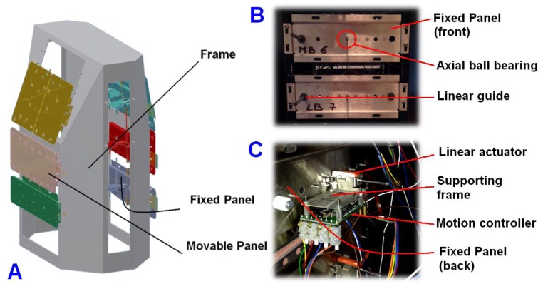
The trajectories of the 8 groups above were estimated by analyzing the thorax movements during the breathing. By means of a virtual plane parallel to the chest wall, each movable panel trajectory line was calculated for each direction (X, Y, and Z). The α angle between each movable panel trajectory and the virtual plane was obtained. Angle analysis showed the necessity to move ULT and URT movable panels with a tilt angle of 20° and ULB and URB with an angle of 10° with respect to the parallel plane. Therefore the simulator frame has been designed with an inclination of the simulated anterior thorax of 20° and an inclination of 10° for the corresponding back zone (Fig. 3A).
Fig. (3).
(A) 3D CAD representation of the bio-Inspired mechatronic Chest Wall Simulator (CWS), (B) Front of a fixed panel, (C) Back of a fixed panel.
The same α angle was estimated at the beginning () and at the ending () of each breathing phase, for 1 minute. For all movable panels the %Δα as expressed in Eq. 3 was estimated to be < 5%. Hence, the angles of movable panels were considered constant during the breathing.
| (3) |
Based on the results above, we rejected a design that considered one actuator for each marker and developed a simulator composed of 8 movable panels (each one controlled by a linear actuator), one for each group of markers previously found. This solution has reduced some drawbacks in terms of costs, control implementation issues and bulky problems.
The CWS (Fig. 3A) was composed of (a) a metallic frame for supporting, (b) 8 fixed panels (Fig. 3B), (c) 8 linear actuators and (d) 8 motion controllers are fixed to panels above by means of supporting frames (Fig. 3C). The shaft of each actuator acts on a movable panel through a hole and an axial ball bearing, so (d) 8 movable panels were provided, made in aluminum and characterized by different mass and size (Table 2) with 2 mm thickness, they are also covered with several holes in order to decrease the air resistance and to reduce the mass. A linear guide was installed to each fixed panel (Fig. 3B), aiming to sustain the correspondent movable panel and to avoid its rotation.
Table 2.
Movable Panels: size, mass and inertia factor (KJ).
| Movable Panel | Size | Mass (g) | KJ | ||
|---|---|---|---|---|---|
| Length (mm) | Height (mm) | ||||
| Front | URT | 120 | 150 | 41.1 | 6.9 |
| ULT | 120 | 150 | 41.6 | 6.9 | |
| RCA | 220 | 115 | 80.9 | 12.6 | |
| AB | 232 | 79 | 46.6 | 7.7 | |
| Back | URB | 125 | 160 | 64.8 | 10.3 |
| ULB | 125 | 160 | 51.4 | 8.3 | |
| MB | 260 | 110 | 70.7 | 11.1 | |
| LB | 270 | 70 | 50.1 | 8.2 | |
Referring to Table 2, some features of the coupled load have been investigated to optimize motion controllers: panel size, mass and shape have been chosen to limit the inertia factor value KJ for each pair actuator-panel (Eq. 4).
| (4) |
where Mload is the actuator-panel mass, and Mshaft is the motor shaft mass (i.e., 7.0 g).
Referring to Table 1 and Fig. (1), in order to control panels displacement the CWS has been embedded with eight linear DC actuators (40 μm repeatability, 140 μm accuracy), each one equipped with a 40 mm shaft length (maximum speed of 2.4 m/s and maximum acceleration of 147.5 m/s2) and a motion controller. The actuator model was chosen on a detailed forces study: considering external forces, friction forces, parallel forces and the movable panel mass, the continuous force delivered by each motor resulted good enough in all movements. A 3Φ delta-wound coil drove the output shaft that embeds permanent magnets. Each actuator stator has been equipped with 3 Hall sensors (1/3000 polar pitch resolution, corresponding to 4 μm linear shaft displacement) as control feedback, providing the position of each panel. Due to the proximity of magnetic sources and actuators housings, as well as the presence of ferromagnetic materials, the CWS has been manufactured using non-ferromagnetic (and non-photo-reflective) panels and structures.
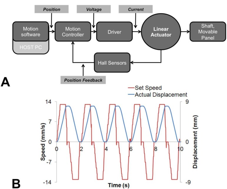
The motion control scheme is shown in Fig. (4a): a serial RS 232 network allowed the communication between all the motion controllers and a Host PC, in which commercial motion software was installed. All linear actuators are simultaneously ad independently driven: all of them are subjected to a trapezoidal speed profile as in Fig. (4b) (i.e., acceleration phase, constant speed phase, and deceleration phase).
Fig. (4).
(A) Motion Control Scheme for a single actuator, (B) Trapezoidal speed profile and relative displacement at 8 mm of target displacement and 13 mm/s maximum set speed, collected from Hall sensors.
3. EXPERIMENTS AND RESULTS
3.1. Dynamic Response Analysis
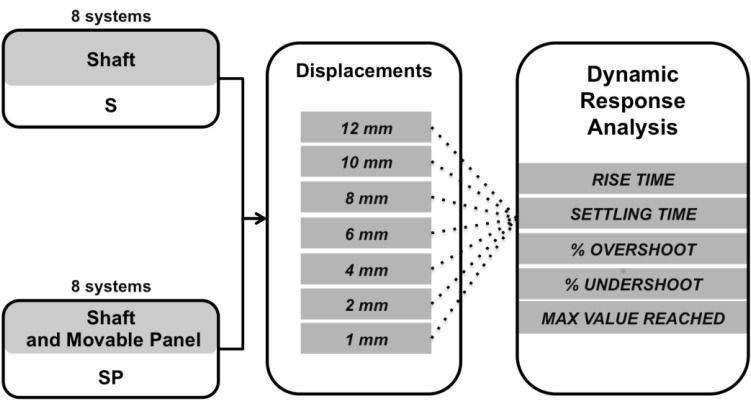
The dynamic response of the CWS has been investigated for each of the 8 systems made up of (i) an actuator, (ii) a motion controller, and (iii) a movable panel, where the panel displacement ranged from 1 mm to 12 mm (Fig. 5), that corresponds to the normal physiological interval in quiet breathing [44-47].
Fig. (5).
Experimental protocol for dynamic response analysis.
The aim of these experiments was two fold: (i) the dynamic response analysis allows controller parameters setting and optimization, with particular focus on PID gains; (ii) the measurement of time used by the system to complete the set displacement establishes the maximum number of breathings per minute (bpm) that the CWS can simulate, in fact, it can be considered the time employed by the CWS to perform its fastest inspiratory or expiratory phase.
In our analysis, we considered two different operation modes for each system: (i) without the panel, where the actuator moves only the shaft (S); and (ii) with the panel, where the actuator moves both the shaft and the movable panel (SP). The dynamic response has been evaluated by setting 7 different displacement values (Fig. 5) in order to widely cover the thoracic wall movements during quiet breathing (i.e. between 1 and 12 mm) [46, 47]. During each trial, the motion controller drives the actuator with the maximum acceleration and maximum speed.
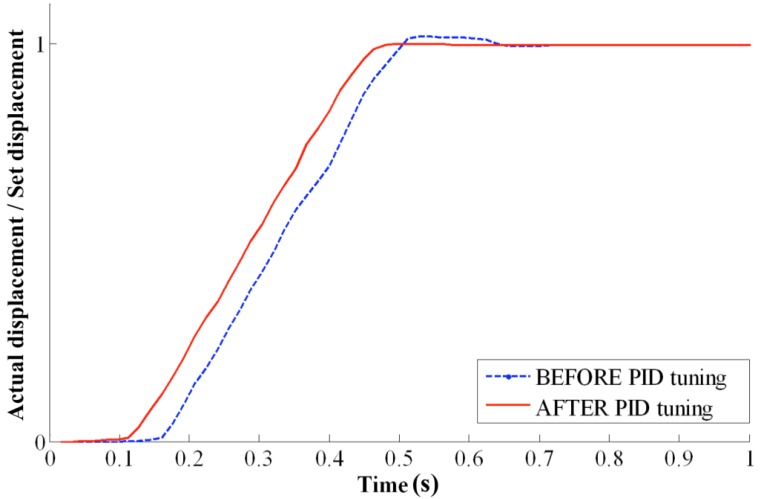
A typical displacement trend, expressed as the ratio between the actual and the set displacement, is shown in Fig. (6) where dashed and solid curves refer to before and after the PID gain optimization, respectively. Actual displacement signals were recorded by Hall sensors embedded into the actuator stator. Analysis of S and SP dynamic responses has been performed on the following quantities: rise time2, settling time3, overshoot4, undershoot5 and maximum value reached. For settling time analysis a ± 5% dynamic error band was set.
Fig. (6).
SP dynamic response (Shaft and movable Panel RCA) for a set displacement of 12 mm, before and after PID gain tuning.
For all the 8 systems in the S configuration, the rise time was lower than 0.32 s, whereas the settling time is lower than 0.46 s; referring to the SP configuration, the rise time was always lower than 0.29 s, whereas the settling time lower than 0.50 s.
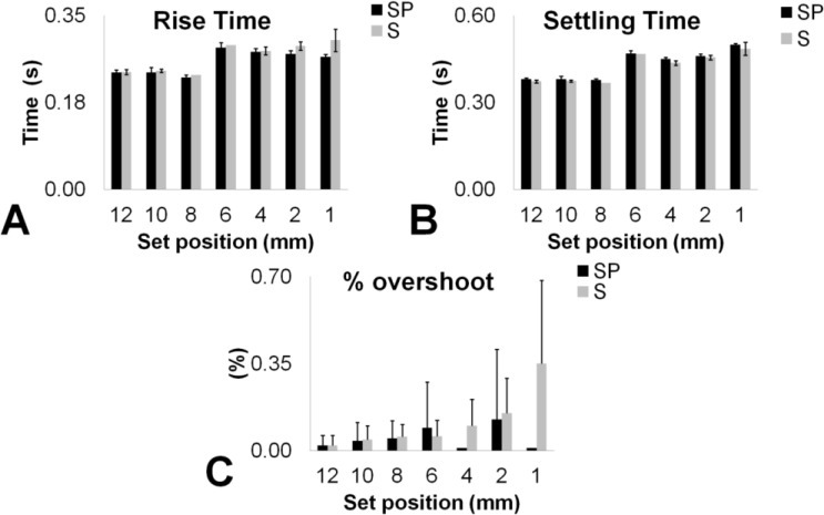
In Fig. (7), the main results for all the above-defined quantities are shown, where black and grey bars refer to mean values on all the 8 systems in SP and S configuration respectively. In particular, for each displacement set are illustrated rise time (Fig. 7A), settling time (Fig. 7B) and percentage overshoot %OS (Fig. 7C); the last quantity was obtained starting from the maximum value reached in the response curve.
Fig. (7).
Rise time (A), Settling time (B) And overshoot (C) Data for experimental set positions, in S and SP operation mode.
From plots in Fig. (7), no significant difference was observed between configurations results, whereas a slight discrepancy has been observed between displacements that are lower and higher than 6 mm for rise and settling time measurements (Fig. 7A,7B). In Fig. (7c), %OS resulted always lower than 0.7% for both of the configurations. Except for 6 mm displacement, SP condition showed a lower %OS, likely due to panel damping.
From results above the dynamic response for both configurations seem to be suitable in the range of physiological interest (i.e., up to 60 bpm) moreover the analysis could be reduced to a lower number of displacements (e.g. 1 mm, 6 mm, and 12 mm).
In comparison to each set position, the maximum value reached in the response curve was analyzed. Data showed a good accuracy in position for both S and SP settings and all target position (Table 3): the highest percentage error e% = 100 · (MRVset - MRVP) / MRVset between nominal (MRVset) and reached values (MRVP) was 0.4%.
Table 3.
Maximum value reached in S and SP configurations (mean ± standard deviation).
| Set Position (μm) | Reached Position (μm) | |
|---|---|---|
| S | SP | |
| 12 000 | 12 000 ± 4 | 12 000 ± 8 |
| 10 000 | 10 004 ± 8 | 10 000 ± 8 |
| 8 000 | 8 004 ± 4 | 8 000 ± 8 |
| 6 000 | 6 004 ± 4 | 6 004 ± 12 |
| 4 000 | 4 004 ± 4 | 3 996 ± 4 |
| 2 000 | 2 004 ± 4 | 2 000 ± 8 |
| 1 000 | 1 004 ± 4 | 996 ± 4 |
The percentage undershoot, obtained from the minimum value reached in the response curve below the final value for each set position, was absent in SP configuration, likely due to the higher damping of panels, and it was always lower than 0.4% under S configuration.
3.2. Accuracy and precision assessment during breathing simulation
Repeatability of CWS swept volume, obtained by the movable panels, has been studied. Repeatability in volume (V) was mostly related to the motor shaft linear displacements (D) repeatability according to Eq. 5:
| (5) |
where Ai is the surface of the i-th movable panel and subscript j refers to the j-th time instant during the simulated breathing. Hence, displacement repeatability could be a robust indicator of CWS ability to provide equal volumes in nominally equal simulated breaths.
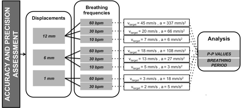
Three different target displacements, covering the whole range of interest, were used to assess accuracy and precision: the simulator was tested at 12, 6 and 1 mm and for 3 different frequency values, i.e., 60 bpm (1 Hz), 30 bpm (0.5 Hz) and 10 bpm (0.17 Hz), except for 1 mm displacement, that was not tested at 10 bpm because the technological limitations in shaft speed settings < 1 mm/s.
During experiments above, accuracy and precision assessments have been performed in SP condition, moving all the panels together and simultaneously for 1 minute. The experimental protocol is shown in Fig. (8).
Fig. (8).
Schematic of experimental protocol for accuracy and precision assessment.
The aim of accuracy and precision assessment protocol was two fold: i) to assess the measurement errors between set and measured values and ii) to analyze the repeatability of movement of the CWS starting from each SP system analysis. For each nominal displacement (set position) and breathing frequency pair, maximum and minimum values of the shaft position were measured from the Hall sensor signal through an ad hoc developed algorithm in MatlabTM environment: the two quantities above can be assumed as positions of the movable panels at the start and the end of inspiratory or expiratory phase respectively.
Ten trials have been repeated for each setting (i.e., frequency and target position), measuring peak to peak values and the breathing period duration: peak to peak values (P-P) have been related to the measured displacement of each panel that has been obtained as difference between maximum and minimum consecutive values. Numerical results are reported in Table 4 as mean ± standard deviation over ten repeated measures, where displacement error Δ is the difference between set and measured displacement.
Table 4.
Measured displacement (P-P) and displacement error Δ at 3 breathing frequencies, for 12, 6 and 1 mm set displacements.
| Set Displacement (mm) | Measured Displacement (P-P) (mm) | Displacement Error δ (mm) | ||||
|---|---|---|---|---|---|---|
| 60 bpm | 30 bpm | 10 bpm | 60 bpm | 30 bpm | 10 bpm | |
| 12 | 11.998±0.005 | 11.993±0.012 | 12.004±0.013 | 0.002 | 0.007 | -0.004 |
| 6 | 5.973±0.027 | 6.000±0.008 | 6.000±0.004 | 0.027 | 0.001 | 0.001 |
| 1 | 0.996±0.003 | 1.000±0.004 | - | 0.004 | 0.001 | - |
The highest data spread was obtained at 60 bpm and 6 mm of nominal displacement (standard deviation of 27 μm); the lowest was obtained at 60 bpm and 1 mm (standard deviation of 3 μm).
Starting from measured displacement (P-P), precision error (E%) was estimated in (6) as follows:
| (6) |
where t9 = 2.262 was the coverage factor for a t-Student distribution with nine degrees of freedom and a 95% level of confidence, and SD was the standard deviation. The highest %E value (i.e., 0.32%) was obtained at 60 bpm and 6 mm, the lowest one (i.e., 0.03%) at 60 bpm and 12 mm.
To assess the capability of the system to follow the set displacement, Δ was calculated over all conditions: its values ranged up to 9 μm and no significant differences were found between measurement and set displacements (Kruskal-Wallis test, p – value > 0.05).
The breathing period duration was also evaluated as difference ΔT between the measured breathing period from displacements signals ( TMeasured ) and the set one ( TSet ). TSet represents the duration of a complete simulated breath (from the beginning of inspiration to the ending of expiration) set in the trapezoidal motion profile through Motion Software to each motion controller. Ten trials were repeated for each setting; the analysis was performed at three breathing frequencies (60 bpm, 30 bpm, and 10 bpm), corresponding to respiratory periods of 1 s, 2 s, and 6 s, respectively (Table 5). ΔT values range up to 0.095 s.
Table 5.
Measured breathing period (TMeasured) and difference ΔT from the set one ( TSet) for different displacements.
| (s) | (s) | (s) | ||||
|---|---|---|---|---|---|---|
| 12 mm | 6 mm | 1 mm | 12 mm | 6 mm | 1 mm | |
| 1.000 | 1.043 ± 0.003 | 1.040 ± 0.003 | 1.090 ± 0.005 | 0.043 | 0.040 | 0.090 |
| 2.000 | 2.050 ± 0.019 | 2.062 ± 0.008 | 2.076 ± 0.023 | 0.050 | 0.062 | 0.076 |
| 6.000 | 6.038 ± 0.052 | 6.070 ± 0.042 | - | 0.038 | 0.070 | - |
Kruskal-Wallis test for medians showed no significant difference between and values, in Table 5. These results suggest that CWS is suitable to provide breathing periods that are not dependent on panel displacement in the whole testing range (up to 60 bpm).
4. DISCUSSION
The metrological analysis of optoelectronic systems for gait analysis is widely discussed in the literature. Despite the growing clinical interest on OEP systems, the literature lacks investigations regarding their metrological properties [24, 25].
In this work we have described a custom made, bio-inspired, mechatronic chest wall simulator (CWS) designed and controlled to assess the metrological performances of the OEP system: a human chest wall has been simulated during quite breathing by moving eight movable panels used as chest wall compartments.
In dynamic response analysis, controller settings were optimized in two different S and SP operation modes. Rise and settling time measurements (Fig. 7A, 7B) for each system and at different set displacement (1-12 mm) showed no difference between S and SP operation modes (p > 0.05), because of robust PID gain and controller parameters tuning: rise and settling time values up to 320 ms and 500 ms have been found, respectively. CWS allows to simulate respiratory frequency up to ~ 60 bpm. Moreover, percentage overshoot analysis (Fig. 7C) demonstrated a higher value of 0.7% for both operation modes. Furthermore, SP condition showed lower %OS values, likely due to panel damping. The absence of percentage undershoot in SP was observed as result of the same phenomenon.
Maximum value reached analysis (Table 3) showed a good CWS accuracy in position for both S and SP settings and at all target position: the highest percentage error measured was 0.4%.
Accuracy and precision during breathing simulation have been assessed only at 3 different displacements equal to 12, 6 and 1 mm: the displacements above allow to simulate (Eq. 5) human-like tidal volume up to 2.01 L within the physiological range [48]. Results in Table 4 and Table 5 were very encouraging and showed that the highest estimated precision error was 0.32%, while the lowest accuracy, expressed as difference between measured and set displacement, was 0.027 mm. These values could be considered widely acceptable for most of our CWS applications, also because a 30 μm OEP discrimination threshold [25].
On the other hand in Table 5 a good agreement between breathing periods collected from displacements signals Tmeasured and the set ones (Tset) has been shown: nevertheless a maximum value of their difference ∆T equal to 0.09 s was found at 60 bpm breathing frequency, no significant differences between Tset and Tmeasured were found for measurements (p > 0.05). Moreover the agreement between Tset and Tmeasured has been further improved by means of a motion control script optimization. However position, speed and acceleration of each actuator are well known in each moment thanks to the continuous acquisition of Hall sensors signals. Hence for each actuator and each panel actual displacement, simulated tidal volume and breathing frequency can be rightly estimated.
5. CONCLUSION
Despite the growth of research interest into OEP systems clinical application, as evidenced by the growing number of scientific publications, its metrological performances have not been extensively investigated yet. With this aim, a custom made Chest Wall Simulator (CWS) composed of 8 compartments has been developed and characterized: compartments size and trajectories have been designed on literature reviews and experimental data from healthy subjects, so that the system developed simulates chest wall displacements (also thoracic anterior and posterior asymmetries) over the normal adult physiological range and allows sweeping human-like tidal volumes up to 2.01 L. Moreover, it performs respiratory phase lasting less than 0.50 s at all operative conditions, from 10 bpm up to 60 bpm. The device shows good performances in terms of displacement precision (maximum %E = 0.32 %) and accuracy: the maximum percentage error on swept tidal volumes is 0.01 L at 12 mm set displacement, while its accuracy, evaluated as the maximum difference between set and measured displacement, is lower than 9 μm, that is far below usual OEP discrimination threshold and so it can be considered acceptable for the particular field of interest. Finally, the error between the measured breathing period (starting from displacement signals) and the set one was always lower than 0.09 s.
The necessity to use eight movable panels and actuators represents the main limitation of our CWS and does not allow to completely reproduce the whole human chest-wall kinematic, i.e., it has not been possible to simulate the lateral chest wall kinematic (Fig. 1b, 1c). However good dynamic and static performances encourage the use of the proposed CWS for OEP system testing. Nevertheless other tests are going to be collected for a complete metrological characterization of the device and its performances improvement.
ACKNOWLEDGEMENTS
Research is partially funded by Italian MIUR PRIN 2012 project (Prot. 20127XJX57).
Footnotes
In respiratory physiology lung volumes and flows are standardized to barometric pressure at sea level, body temperature, saturated with water vapor: Body temperature and pressure, saturated.
Time interval between the instant when the output signal, starting from zero, reaches a small specified percentage (for instance 10%) of the final steady-state value, and the instant when it reaches for the first time a specified large percentage (for instance 90%) of the same steady state value.
Time for the output to reach and remain within 1% of output span of its final steady value (CEI EN 61298-2:1997-06).
Maximum transient deviation from the final steady state value of the output variable, expressed in % of the difference between the final and the original steady state values. In other words the percent overshoot is the percent by which a system exceeds its final steady-state value (CEI EN 61298-2:1997-06)
Minimum output swing below the final value.
CONFLICT OF INTEREST
The authors had no conflict of interest when performing the study or when preparing the manuscript.
REFERENCES
- 1.Andriacchi T P, Alexander E J. (Studies of human locomotion): past, present and future”. J. Biomech. 2000;33:1217–1224. doi: 10.1016/s0021-9290(00)00061-0. [DOI] [PubMed] [Google Scholar]
- 2.Ferrigno G, Borghese NA, Pedotti A. “Pattern recognition in 3D automatic human motion analysis”. ISPRS J Photogramm. 1990;45:227–246. [Google Scholar]
- 3.Wong W Y, Wong M S, Lo K H. “Clinical applications of sensors for human posture and movement analysis: a review”. Prosthet. Orthot. Int. 2007;31:62–75. doi: 10.1080/03093640600983949. [DOI] [PubMed] [Google Scholar]
- 4.Goffredo M, Schmid M, Conforto S, Carli M, Neri A, D'Alessio T. “Markerless human motion analysis in Guss-Laguerre transform domain: application to sit-to-stand in young and elderly people”. IEEE Trans. Inf. Technol. Biomed. 2009;13:207 – 216. doi: 10.1109/TITB.2008.2007960. [DOI] [PubMed] [Google Scholar]
- 5.Goffredo M, Schmid M, Conforto S, D'Alessio T. “A markerless sub-pixel motion estimation technique to reconstruct kinematics and estimate the centre of mass in posturography”. Med. Eng. Phys. 2006;28:719–726. doi: 10.1016/j.medengphy.2005.10.007. [DOI] [PubMed] [Google Scholar]
- 6.Branca F P, Sciuto S A, Scorza A. “Comparative evaluation of ultrasound scanner accuracy in distance measurement”. Rev. Sci. Instrum. 2012;83:105103. doi: 10.1063/1.4755811. [DOI] [PubMed] [Google Scholar]
- 7.Marinozzi F, Branca F P, Bini F, Scorza A. “Calibration procedure for performance evaluation of clinical Pulsed doppler Systems”. Measurement. 2012;45:1334–1342. [Google Scholar]
- 8.Perry J, editor. Slack Inc. New Jersey. 1992. Gait Analysis: Normal and Pathologic Functions. [Google Scholar]
- 9.Ancillao A, Galli M, Vimercati S L, Albertini G. “An optoelectronic based approach for handwriting capture”. Comput. Methods Prog. Biomed. 2013;111: 357–365. doi: 10.1016/j.cmpb.2013.05.002. [DOI] [PubMed] [Google Scholar]
- 10.Scorza A, Battista L, Silvestri S, Sciuto S A. “Design and development of a rheometer for biological fluids of limited availability”. Rev. Sci. Instrum. 2014;85:105105. doi: 10.1063/1.4897490. [DOI] [PubMed] [Google Scholar]
- 11.Sofuwa O, Nieuwboer A, Desloovere K, Willems A.M., Chvret F., Jonkers I. Quantitative gait analysis in Parkinson's disease comparison with a healthy control group . .Arch. Phys. Med. Rehabil. . 2005;86: 1007–1013. doi: 10.1016/j.apmr.2004.08.012. [DOI] [PubMed] [Google Scholar]
- 12.Õunpuu S. “Gait analysis is a viable tool for the assessment of transverse plane motion in children with cerebral palsy”. Dev. Med. Child Neurol. 2013;55:878–879. doi: 10.1111/dmcn.12227. [DOI] [PubMed] [Google Scholar]
- 13.Carraro E, Zeme S, Ticcinelli V, Massaroni C, Santin M, Peretta P, Martinuzzi A, Trevisi E. “Multidimensional outcome measure of selective dorsal rhizotomy in spastic cerebral palsy”. Eur. J. Paediatr. Neurol. 2014;18:704–713. doi: 10.1016/j.ejpn.2014.06.003. [DOI] [PubMed] [Google Scholar]
- 14.Merlo A, Zemp D, Zanda E, Rocchi S, Meroni F, Tettamanti M, Recchia A, Lucca U, Quadri P. “Postural stability and history of falls in cognitively able older adults: The Canton Ticino study”. Gait Posture. 2012;36:662–666. doi: 10.1016/j.gaitpost.2012.06.016. [DOI] [PubMed] [Google Scholar]
- 15.Masiero S, Carraro E. “Upper limb movements and cerebral plasticity in post-stroke rehabilitation”. Aging Clin. Exp. Res. 2008;20:103–108. doi: 10.1007/BF03324755. [DOI] [PubMed] [Google Scholar]
- 16.Battista L, Scorza A, Sciuto SA. “Fiber-Optic Flow Sensor for the Measurement of Inspiratory Efforts in Mechanical Neonatal Ventilation”. Sensors and Microsystems Lecture Notes in Electrical Engineering Springer International Publishing. 2014;268:453–457. [Google Scholar]
- 17.Battista L, Sciuto S A, Scorza A. “An air flow sensor for neonatal mechanical ventilation applications based on a novel fiber-optic sensing technique”. Rev. Sci. Instrum. 2013;84:035005. doi: 10.1063/1.4798298. [DOI] [PubMed] [Google Scholar]
- 18.Schmid M, Conforto S, Bibbo D, D'Alessio T. “Respiration and postural sway: Detection of phase synchronizations and interactions”. Hum. Mov. Sci. 2004;23:105–119. doi: 10.1016/j.humov.2004.06.001. [DOI] [PubMed] [Google Scholar]
- 19.Battista L, Scorza A, Sciuto S A. “Preliminary Evaluation of a Simple Optical Fiber Measurement System for Monitoring Respiratory Pressure in Mechanically Ventilated Infants”. in Proceedings of the 9th IASTED International Conference on Biomedical Enginering BioMed . 2012;2012:443–449. [Google Scholar]
- 20.Battista L, Scorza A, Lupi G, Sciuto SA. “Experimental investigation on dynamical performances of a novel fiber-optic pressure sensor for pulmonary ventilation”.in Proceedings of the 20th IMEKO TC4 International Symposium and 18th IMEKO TC4 International Workshop on ADC and DAC Modelling and Testing: Research on Electrical and Electronic Measurement for the Economic Uturn. 2014:315–319. [Google Scholar]
- 21.Battista L, Sciuto S A, Scorza A. “Preliminary evaluation of a fiber-optic sensor for flow measurements in pulmonary ventilators”. in Proceedings of MeMeA 2011 - 2011 IEEE International Symposium on Medical Measurements and Applications. 2011 [Google Scholar]
- 22.Battista L, Scorza A, Sciuto SA. “Experimental characterization of a novel fiber-optic accelerometer for the quantitative assessment of rest tremor in parkinsonian patients”. in Proceedings of the 9th IASTED International Conference on Biomedical Enginering BioMed. 2012;2012:437–442. [Google Scholar]
- 23.Ferrigno G, Pedotti A. “ELITE: a digital dedicated hardware system for movement analysis via real-time TV signal processing”. IEEE Trans. Biomed. Eng. 1985;32:943–950. doi: 10.1109/TBME.1985.325627. [DOI] [PubMed] [Google Scholar]
- 24.Cala S J, Kenyon C M, Ferrigno G, Carnevali P, Aliverti A, Pedotti A, Macklem P T, Rochester D F. “Chest wall and lung volume estimation by optical reflectance motion analysis”. J. Appl. Physiol. 1996;81:2680–2689. doi: 10.1152/jappl.1996.81.6.2680. [DOI] [PubMed] [Google Scholar]
- 25.Gorini M, Iandelli I, Misuri G, Bertoli F, Filippelli M, Mancini M, Duranti R, Gigliotti F, Scano G. “Chest wall hyperinflation during acute bronchoconstriction in asthma”. Am. J. Respir. Crit. Care Med. 1999;160:808–816. doi: 10.1164/ajrccm.160.3.9712088. [DOI] [PubMed] [Google Scholar]
- 26.Aliverti A, Dellacà R, Pelosi P, Chiumello D, Pedotti A, Gattinoni L. “Optoelectronic plethysmography in intensive care patients”. Am. J. Respir. Crit. Care Med. 2000;161:1546–1552. doi: 10.1164/ajrccm.161.5.9903024. [DOI] [PubMed] [Google Scholar]
- 27.Aliverti A, Stevenson N, Dellaca R L, Lo Mauro A, Pedotti A, Calverley P M. “Regional chest wall volumes during exercise in chronic obstructive pulmonary disease”. Thorax. 2004;59:210–216. doi: 10.1136/thorax.2003.011494. [DOI] [PMC free article] [PubMed] [Google Scholar]
- 28.Aliverti A, Dellacà R L, Pedotti A. “Transfer impedance of the respiratory system by forced oscillation technique and optoelectronic plethysmography”. Ann. Biomed. Eng. 2001;29:71–82. doi: 10.1114/1.1335536. [DOI] [PubMed] [Google Scholar]
- 29.Aliverti A, Carlesso E, Dellacà R, Pelosi P, Chiumello D, Pedotti A, Gattinoni L. “Chest wall mechanics during pressure support ventilation”. Crit. Car. 2006;10:R54. doi: 10.1186/cc4867. [DOI] [PMC free article] [PubMed] [Google Scholar]
- 30.Romagnoli I, Gigliotti F, Galarducci A, Lanini B, Bianchi R, Cammelli D, Scano G. “Chest wall kinematics and respiratory muscle action in ankylosing spondylitis patients”. Eur. Respir J. 2004;24:453–460. doi: 10.1183/09031936.04.00123903. [DOI] [PubMed] [Google Scholar]
- 31.Bastianini F, Silvestri S, Magrone G, Gallotta E, Sterzi S. “A preliminary efficacy evaluation performed by opto-electronic plethysmography of asymmetric respiratory rehabilitation”. in Proceedings of the 31st Annual International Conference of the IEEE Engineering in Medicine and Biology Society EMBC. 2009;2009:849–852. doi: 10.1109/IEMBS.2009.5333569. [DOI] [PubMed] [Google Scholar]
- 32.Bianchi R, Gigliotti F, Romagnoli I, Lanini B, Castellani C, Grazzini M, Scano G. “Chest Wall Kinematics and Breathlessness during Pursed-Lip Breathing in Patients with COPD”. Chest. 2004;125:459–465. doi: 10.1378/chest.125.2.459. [DOI] [PubMed] [Google Scholar]
- 33.Cappa P, Sciuto S A, Silvestri S. “A novel preterm respiratory mechanics active simulator to test the performances of neonatal pulmonary ventilators”. Rev. Sci. Instrum. 2002;73, 6:2411–2416. [Google Scholar]
- 34.Bastianini F, Schena E, Silvestri S. “Accuracy evaluation on linear measurement through opto-electronic plethysmograph”. in Proceedings of the Annual International Conference of the IEEE Engineering in Medicine and Biology Society EMBC. 2012:1–4. doi: 10.1109/EMBC.2013.6609654. [DOI] [PubMed] [Google Scholar]
- 35.Bastianini F, Schena E, Saccomandi P, Silvestri S. “Accuracy evaluation of dynamic volume measurements performed by opto-electronic plethysmograph, by using a pulmonary simulator”. in Proceedings of the Annual International Conference of the IEEE Engineering in Medicine and Biology Society EMBC. 2013:930–933. doi: 10.1109/EMBC.2013.6609654. [DOI] [PubMed] [Google Scholar]
- 36.Combs C D, Walia M K. “The evolution of medical simulators”. in Studies in Health Technology and Informatics. 2009;142:55–58. [PubMed] [Google Scholar]
- 37.Cooper J B, Taqueti V R. “A brief history of the development of mannequin simulators for clinical education and training”. Qual. Saf. Heal. Care. 2004;13:i11–i18. doi: 10.1136/qshc.2004.009886. [DOI] [PMC free article] [PubMed] [Google Scholar]
- 38.Schwid H A. “Anesthesia simulators - technology and applications”. Isr. Med. Assoc. J. 2000;2:949–953. [PubMed] [Google Scholar]
- 39.Aliverti A, Dellacà R, Pedotti A. “Optoelectronic plethysmography: a new tool in respiratory medicine”. Rec. Prog. Med. 2001;92:644–647. [PubMed] [Google Scholar]
- 40.Aliverti A, Dellacà R, Pelosi P, Chiumello D, Gattinoni L, Pedotti A. “Compartmental analysis of breathing in the supine and prone positions by optoelectronic plethysmography”. Ann. Biomed. Eng. 2001;29:60–70. doi: 10.1114/1.1332084. [DOI] [PubMed] [Google Scholar]
- 41.“Optoelectronic plethysmography compedium marker setup; a handbook about marker positioning on subjects in standing and supine positions”. BTS Bioengineering. 2011 [Google Scholar]
- 42.Romagnoli I, Lanini B, Binazzi B, Bianchi R, Coli C, Stendardi L, Gigliotti F, Scano G. “Optoelectronic plethysmography has improved our knowledge of respiratory physiology and pathophysiology”. Sensors. 2008;8:7951–7972. doi: 10.3390/s8127951. [DOI] [PMC free article] [PubMed] [Google Scholar]
- 43.Parreira V F, Vieira D S R, Myrrha M a C, Pessoa I M B S, Lage S M, Britto R R. “Optoelectronic plethysmography: a review of the literature”. Rev. Bras. Fisioter. 2012;16:439–53. [PubMed] [Google Scholar]
- 44.Konno K, Mead J. “Measurement of the separate volume changes of rib cage and abdomen during breathing”. J. Appl. Physiol. 1967;22:407–422. doi: 10.1152/jappl.1967.22.3.407. [DOI] [PubMed] [Google Scholar]
- 45.Pheasant S, Haslegrave C M. Bodyspace: Anthropometry Ergonomics, and the Design of Work. CRC Press. 2005 [Google Scholar]
- 46.Saumarez R C. “An analysis of possible movements of human upper rib cage”. J. Appl. Physiol. 1986;60:678–689. doi: 10.1152/jappl.1986.60.2.678. [DOI] [PubMed] [Google Scholar]
- 47.De Groote A, Wantier M, Cheron G, Estenne M, Paiva M. “Chest wall motion during tidal breathing”. J. Appl. Physiol. 1997;83:1531–1537. doi: 10.1152/jappl.1997.83.5.1531. [DOI] [PubMed] [Google Scholar]
- 48.Branca FP. Fondamenti di ingegneria Clinica. Edizioni Springer Milano. 2000 [Google Scholar]


