Abstract
Many Virtual Environments require walking interfaces to explore virtual worlds much larger than available real-world tracked space. We present a model for generating virtual locomotion speeds from Walking-In-Place (WIP) inputs based on walking biomechanics.
By employing gait principles, our model – called Gait-Understanding-Driven Walking-In-Place (GUD WIP) – creates output speeds which better match those evident in Real Walking, and which better respond to variations in step frequency, including realistic starting and stopping. The speeds output by our implementation demonstrate considerably less within-step fluctuation than a good current WIP system – Low-Latency, Continuous-Motion (LLCM) WIP – while still remaining responsive to changes in user input.
We compared resulting speeds from Real Walking, GUD WIP, and LLCM-WIP via user study: The average output speeds for Real Walking and GUD WIP respond consistently with changing step frequency – LLCM-WIP is far less consistent. GUD WIP produces output speeds that are more locally consistent (smooth) and step-frequency-to-walk-speed consistent than LLCM-WIP.
Index Terms: H.5.1 [Information Interfaces and Presentation], Multimeda Information Systems—Artificial, augmented, virtual realities H.5.2 [Information Interfaces and Presentation], User Interfaces—Input devices and strategies I.3.6 [Computer Graphics], Methodology and Techniques—Interaction techniques I.3.7 [Computer Graphics], Three-Dimenshional Graphics and Realism—Virtual Reality
1 Introduction
Non-vehicular Virtual Environments (VEs) require a locomotion interface. When the virtual world is larger than the available tracked space, Real Walking (where the user actually walks) is no longer straightforward. To enable virtual-world locomotion beyond a confining tracked space, many virtual environment systems employ a Walking-In-Place (WIP) interface.
In a WIP system, the user’s intended motion is communicated to the system through in-place steps. Values derived from the stepping input drive the stationary user’s viewpoint.
When the WIP-system-generated motion fails to match the user’s intended motion, miscommunication occurs. We believe that user-system miscommunication is a significant reason that WIP systems perform poorly when compared to Real Walking [15, 17].
User-system miscommunications cause significant user frustration and distraction. In WIP systems, distraction is particularly troublesome for two reasons. First, locomotion is not most VE systems’ primary goal: Training, data analysis, or therapy are common uses which require walking. When the locomotion interface distracts the user from the goal, the application loses effectiveness. Second, walking’s gestures and output movements are fundamentally related: If one takes a series of steps, one has learned to expect a resulting path with specific speed characteristics. To avoid distracting from the task at hand, the WIP system must interpret the user’s input gestures and generate motion consistent with the user’s expectations. Many portions of WIP motions could be improved. This paper presents a WIP model to generate WIP speeds that better match Real Walking – leading to improved viewpoint movement and optical flow.
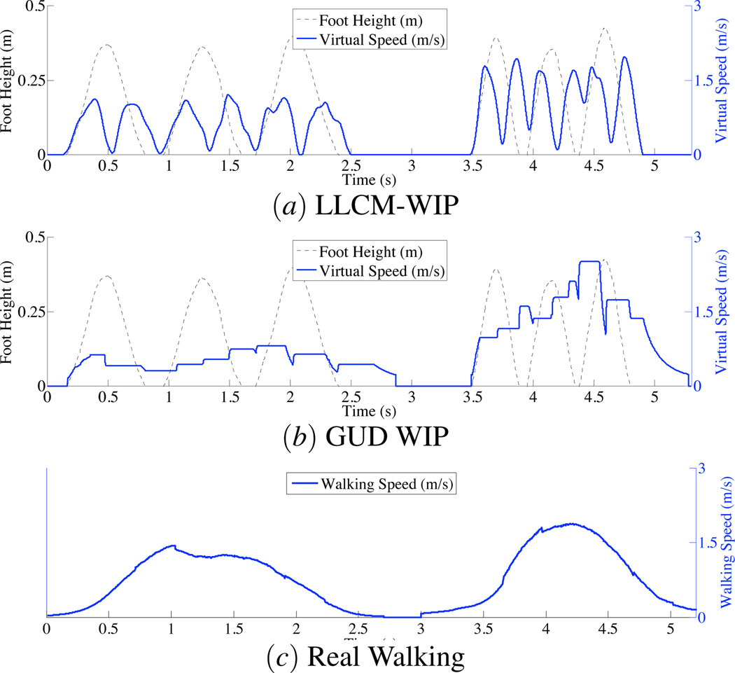
Many very good WIP systems have been proposed. Each has focused on a different system component: Slater, et al.’s Virtual Treadmill illustrated the technique [13]; Templeman, et al.’s Gaiter permitted more expressive walk directions [14]; Razzaque, et al.’s Redirected WIP handled problems arising in three-wall CAVEs™ [12]; Yan, et al.’s system improved starting latency [18]; and Feasel, et al.’s LLCM-WIP improved five walking-speed controls [2]. As only the last (LLCM-WIP) explicitly shared focus with our system – the output speed – we can only compare our results with LLCM-WIP and Real Walking (Figure 1).
Figure 1.
Resulting motion (thicker solid line, right y-axis) from (a) LLCM-WIP [2], (b) GUD WIP, and (c) Real Walking. In this example, the two WIP systems are driven by the same in-place steps (dashed line, left y-axis). The Real-Walking motion is caused by steps taken at approximately the same frequencies as the in-place steps for the WIP systems. Note LLCM-WIP’s resulting speed varies considerably. GUD WIP’s resulting speed is far steady – similar to Real Walking.
Because our WIP model uses the biomechanics of human gait to “understand” stepping gestures, we call it Gait-Understanding-Driven Walking-In-Place, or GUD WIP.1 Our GUD WIP model has the following features:
satisfaction of all LLCM-WIP-proposed speed-control goals: smooth between-step locomotion, continuous within-step speed control, real-world maneuvering, low starting latency, and low stopping latency;
a biomechanics-inspired state machine that measures step frequency at multiple points during in-place steps;
a biomechanics-inspired technique for estimating step frequency with only a fraction of a step completed;
a technique for identifying in-place step events; and
an easily-modifiable technique for transforming step frequencies to gait-understanding-driven output speeds – including details for average users and a method for calibrating for any specific user.
This paper presents the GUD WIP model, describes the UNC implementation, and presents a user study which compares speeds resulting from GUD WIP, LLCM-WIP, and Real Walking.
2 Background: Biomechanics of Real Walking
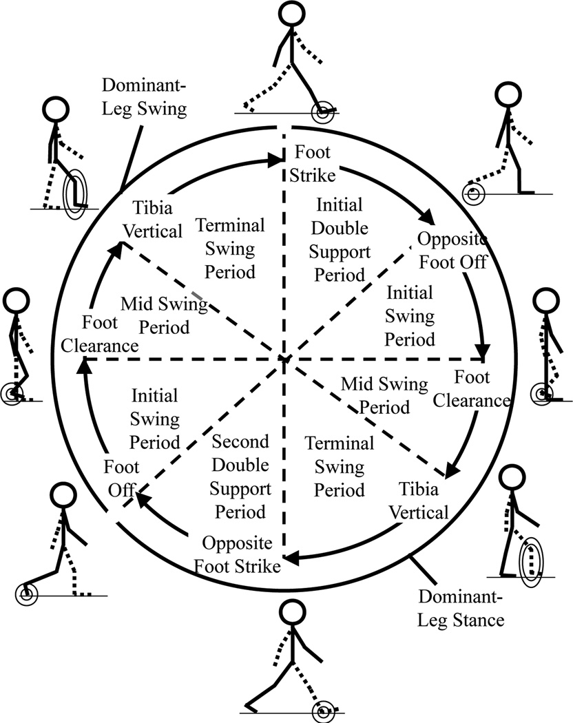
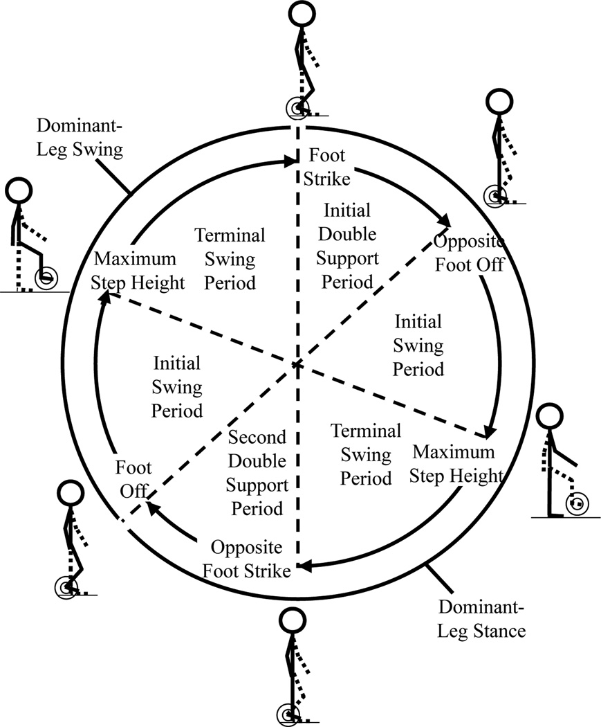
The gait cycle describes the pattern evident in non-pathological human gait [4]. When altering walking speed, humans alter their gait cycle characteristics in well-known ways. By applying gait-cycle principles and variations, virtual walking systems can avoid many user-system miscommunications.
The walking gait cycle (Figure 2) defines a repeating series of periods:
Initial Double Support
Non-dominant-leg Initial Swing
Non-dominant-leg Mid Swing
Non-dominant-leg Terminal Swing
Second Double Support
Dominant-leg Initial Swing
Dominant-leg Mid Swing
Dominant-leg Terminal Swing
These periods are combined into the Stance and Swing phases (Figure 2, outermost arcs).
Figure 2.
The gait cycle defined for rhythmic Real Walking [4]. Gait-cycle periods are shown within the inner cycle. The dominant leg’s stance and swing phases are shown on the outer arcs. Gait-cycle events are named on the inner cycle’s perimeter, and illustrated outside the outer arcs (most important feature circled). Gait-cycle period times are generally not equal.
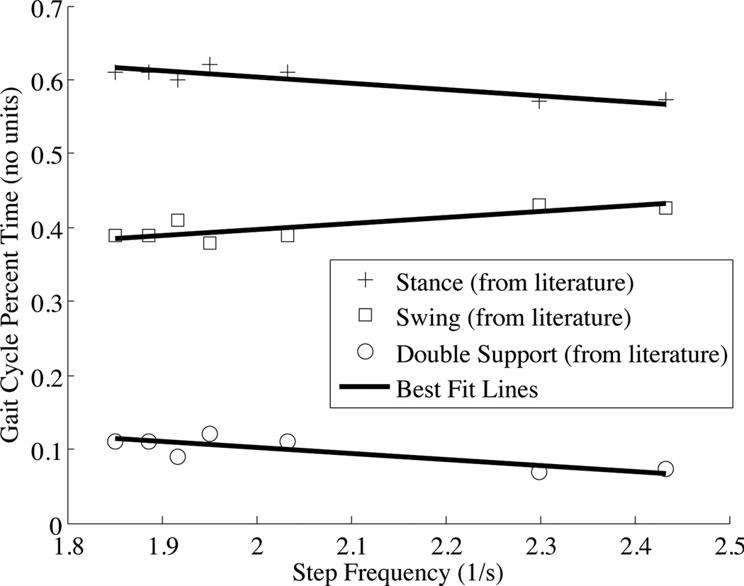
Each period’s percentage of the gait-cycle varies linearly with step frequency (twice gait-cycle frequency, Figure 3). As step frequency increases, the stance phase’s gait-cycle percent-time decreases.
Figure 3.
Step frequency vs. gait-component gait-cycle percent time. Stance, swing, and double-support percent-times vary linearly with step frequency. Data points from [8, 1, 6, 9, 3, 10, 7, 19, 11].
Step frequency (f) and step length (l) produce Real Walking speed (|ν|):
| (1) |
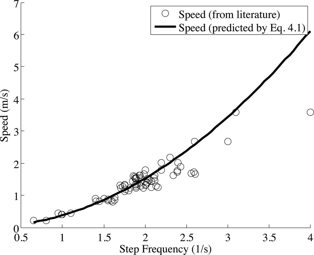
Biomechanics literature indicates that step frequency and length are positively correlated [4]. Furthermore, step length positively correlates with height. By using these relationships, walking speed can be estimated from either step frequency or stride length. This relationship can be measured on any individual. From his data from his and others’, Dean proposed the following relationship between walking speed (|ν|), step frequency (f), and subject height (h) [1]:
| (2) |
Data from several other biomechanics studies support this equation (Figure 4).
Figure 4.
Step frequency vs. walk speed: As step frequency increases, walk speed increases. Equation 2 from [1] (assumed height 1.67m) is fitted to data points from [8, 1, 6, 9, 3, 10, 7, 19, 11].
By applying these gait principles – gait cycle events, periods, and phases, their varation with step frequency, and step frequency’s relationship to walk speed – and by using the user’s height and step frequency, GUD WIP produces near-Real-Walking output speeds.
3 The GUD WIP Model
Subsection 3.1 proposes a gait-cycle-based model for Walking-In-Place systems. Subsection 3.2 describes how GUD WIP fulfills LLCM-WIP’s best-practice speed-control goals.
3.1 GUD WIP During Steady State
Modifying the Real-Walking gait cycle for Walking-In-Place is straightforward (Figure 5): The only significant difference is that the three Real-Walking swing periods (initial, mid, and terminal swing) are merged into two Walking-In-Place swing periods (intial and terminal). The events separating the three Real-Walking swing periods (foot clearance and tibia vertical) do not exist for Walking-In-Place; these are replaced by a single event: maximum foot height.
Figure 5.
The gait cycle for rhythmic in-place stepping. Periods, events, phases, and illustrations correspond with those in Figure 2. Period timings are not generally equal.
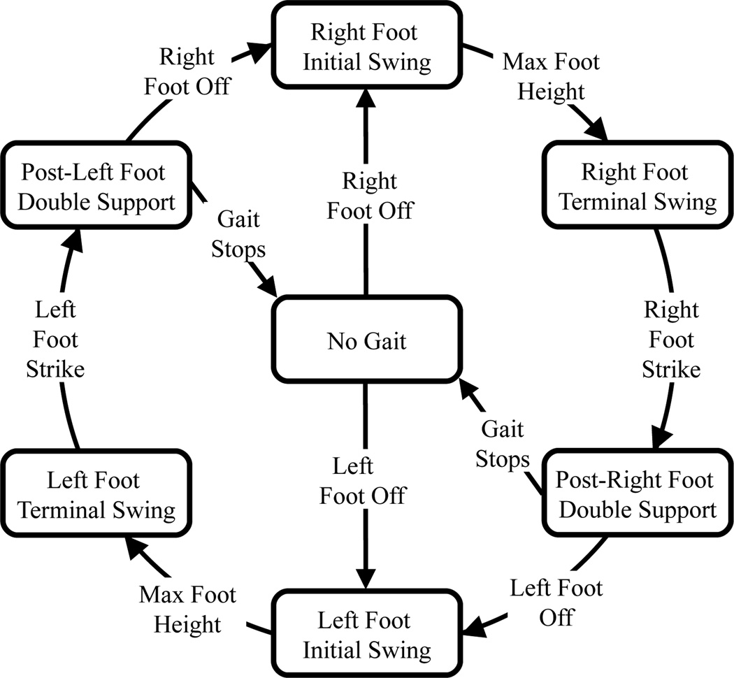
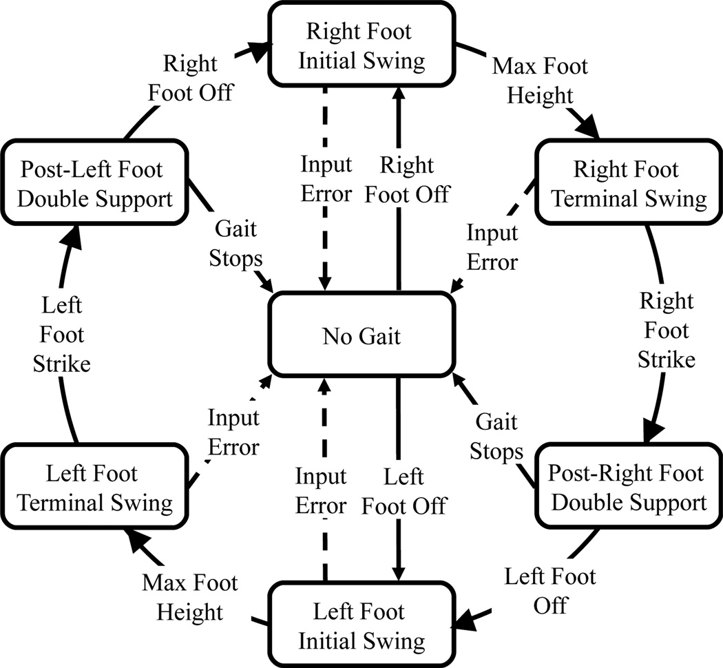
This Walking-In-Place gait cycle can be represented by a simple state machine (Figure 6): a state for each gait-cycle period, an edge for each gait-cycle event, a new no-gait state for extended periods of no input, and appropriate transitions for starting and stopping gait. At all times that inputs do not fulfill a gait-state exit criterion, this state diagram remains in its current state. Self-loops are omitted to simplify the figure.
Figure 6.
GUD WIP state machine. The current state is maintained until a state-exit criterion (shown on transitions) is fulfilled.
The state-transition diagram indicates a direct way to measure steady-state step frequency: After the user completes three successive gait states, the time required to complete those three states is a full step’s time. This frequency estimate persists during the following gait state. When any state finishes, the estimate is updated to include only the three most-recently-completed states.
The estimated frequency combined with the user’s height yields intended speed (Equation 2).
3.2 GUD WIP Fulfills LLCM-WIP’s Speed-Control Goals
GUD WIP achieves the virtual-locomotion speed-control goals presented with LLCM-WIP [2]:
smooth between-step locomotion speed,
continuous within-step speed control,
real-world turning and maneuvering,
low starting latency, and
low stopping latency.
Smooth between-step locomotion speed
Since the measured frequency persists through double support states, motion is smooth between steps – visually smoother than LLCM-WIP (compare Figures 1 (a) and (b)).
Continuous within-step speed control
Since the measured frequency updates at the completion of any state, within-step control is acheived: If the user alters his stepping manner within a step, after the current state completes, the output speed updates accordingly. Admittedly, this is not continuous within steps: It updates at three specific times within each step.
Real-world turning and maneuvering
To permit real-world motion without virtual motion, GUD WIP ignores horizontal foot motions and permits some vertical foot motion without identifying foot off. This allows users to rotate on the spot, or take small real steps so long as the user’s foot does not rise too high and too quickly.
Low starting latency
As described so far, GUD WIP requires three completed states to estimate step frequency – a full step’s latency. Additional gait-cycle analysis enables starting latency to be decreased.
Figure 3 shows that percent time (t%) spent within each Real-Walking gait-cycle phase varies linearly with the step frequency (f). Informal analysis of GUD WIP indicates that the same relationship holds for in-place stepping:
| (3) |
Figure 3 provides the slopes (mstate, seconds) and y-intercepts (bstate, unitless) for each state (is = initial swing, ts = terminal swing, and ds = double support). Those values in step-frequency percent time are as follows:
| (4) |
| (5) |
| (6) |
assuming initial and terminal swing evenly split total swing time.
This linear relationship between state percent time and step frequency can be used to estimate step frequency from a single state’s duration (tstate) and hence decrease starting latency:
| (7) |
Thus, when only initial swing duration is known, the frequency is estimated from that time alone (Equation 7). When both initial and terminal swing durations are known, the frequency is better estimated as the mean of both estimates.
Only during the first initial swing state when stepping has begun, can no frequency be estimated. To remove this starting latency, we use a variant of LLCM-WIP’s predicted speed: LLCM-WIP transforms the vertical speed of the heel to yield the virtual walking speed; we use the maximum value so far in this state as our initial estimate.
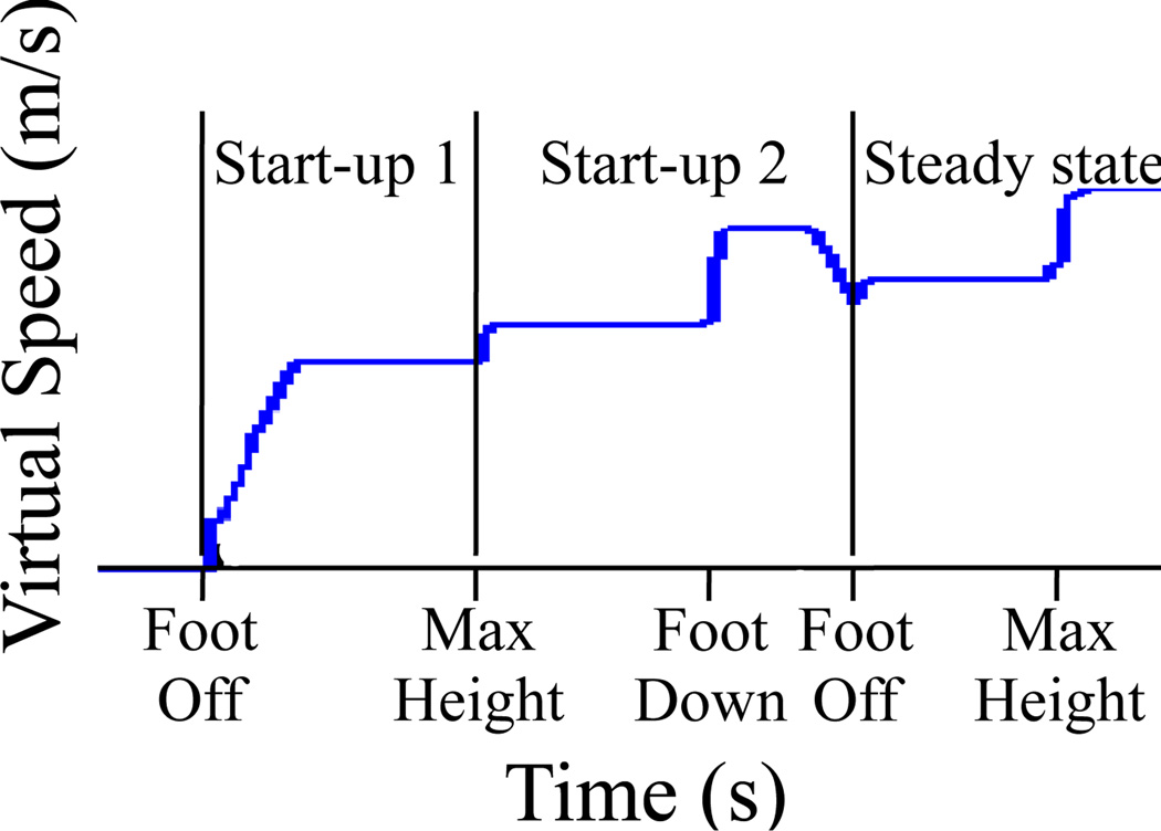
In summary, GUD WIP employs the best gait-based information available at any time (Figure 7):
Start-up 1: Within the first gait state, the maximum LLCM-WIP value produced so far is used.
Start-up 2: When one or two states have completed, the completed states’ durations are combined to estimate step frequency.
Steady state: When continuous stepping has occurred for at least three states, the step frequency is calculated from the three most recent states’ durations.
Figure 7.
Starting latency in GUD WIP. Output speed is divided into three sections: Start-up 1: When the first state has begun (Foot Off detected), use the maximum LLCM-WIP-predicted value. Start-up 2: When one or two states have completed, estimate frequency from Equation 7. Steady state: When three or more states have completed, the frequency is the inverse of the past three states’ duration.
Low stopping latency
GUD WIP’s stopping method also employs gait-understanding-driven state-duration prediction. In short, if double-support state lasts too long (based on a state-duration estimate), “Gait Stops” is identified (see Figure 6).
Given step frequency (f), the current state’s expected duration (tstate) is estimated by inverting Equation 7:
| (8) |
Upon transitioning to a new state, GUD WIP estimates the new state’s duration. If the new state exceeds its estimated duration, the step frequency estimate decreases to account for this over-long state (Equation 7). Thus, the frequency smoothly decreases until the next state begins.
The gait-stopping condition is a special over-long-state response for double-support states. Differentiating between-step Double Support from after-last-step No Gait is inherently difficult: For both, the user keeps both feet planted on the ground.
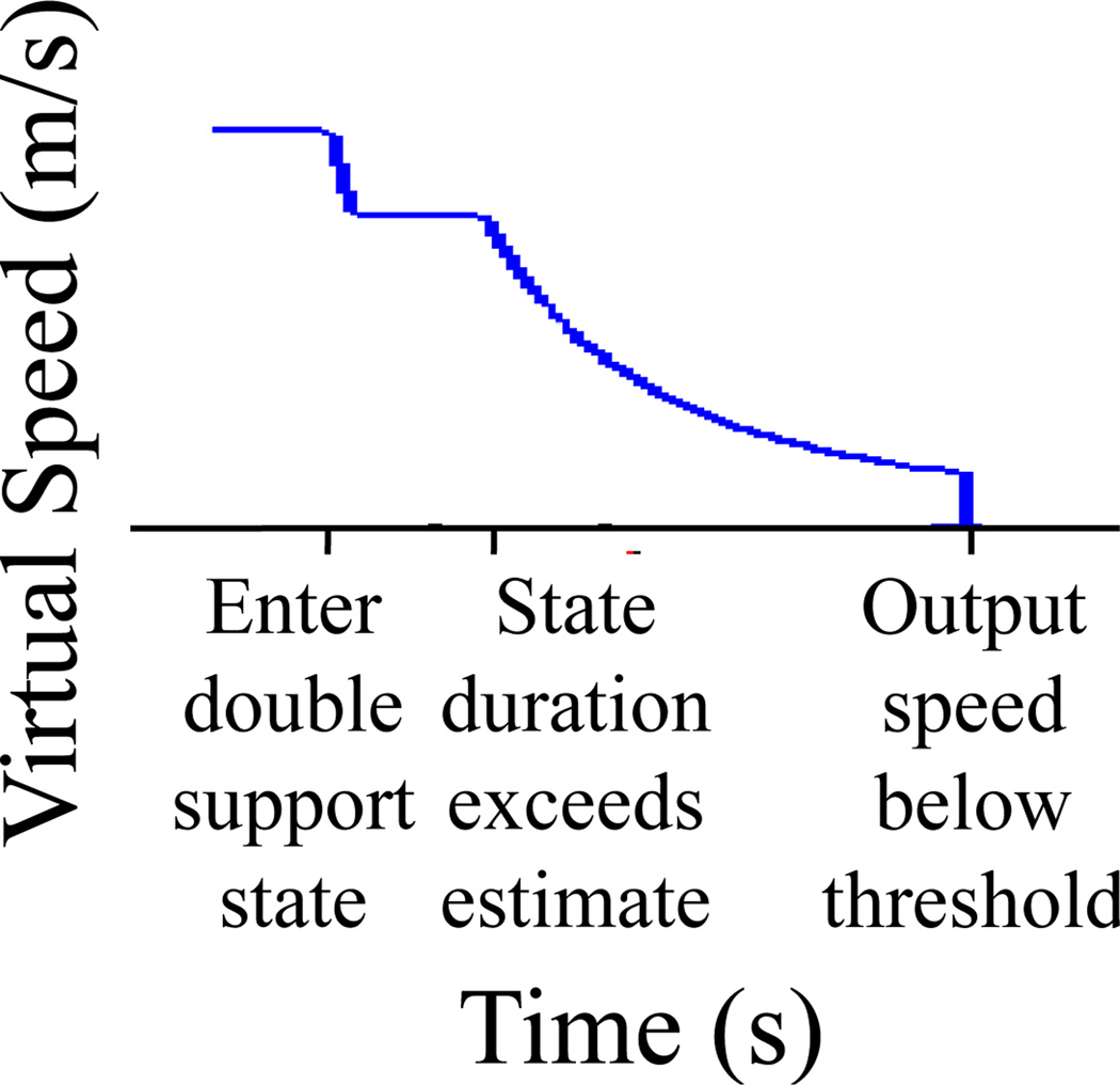
In order to transition from the assumed post-step state (Post-Right/Left Double Support) to the No Gait state, once step frequency in an over-long Double Support state decreases below a threshold, GUD WIP assumes the user intends to stop, and forward motion is halted (Figure 8). We threshold at 0.8 Hz, as rhythmic in-place stepping does not usually occur below it. This means that virtual motion does not stop until approximately 500ms after the last step ceases – approximately five times LLCM-WIP’s stopping latency.
Figure 8.
Stopping latency in GUD WIP. Output speed during stopping with three important events marked: First, upon entering a double support state, the new state’s duration is estimated (Equation 8). Second, when that estimate is exceeded, the output speed decreases to match the frequency required by the state’s actual duration (Equation 7). Third, once the step frequency drops below a minimum threshold, all output is stopped.
There is an inherent trade-off between LLCM-WIP’s goals of low stopping latency and between-step, continuous motion. If continuous motion between low-frequency steps is desired, stopping latency must exceed a Double Support state’s duration at that frequency. If lower stopping latency is desired, the frequency-cutoff threshold can be increased – but this removes smooth, low-frequency, between-step motion. Within GUD WIP, we chose continuous motion between steps over faster stopping latency. This tradeoff is alleviated by slowing virtual speed smoothly in over-long states. We believe GUD WIP’s smooth stop (Figure 1 (b)) better matches Real Walking’s stopping characteristics (Figure 1 (c)).
4 UNC GUD WIP Implementation and Performance
Any implementation of the described model is a GUD WIP implementation. This section describes the UNC prototype’s key implementation details: identifying gait events, and implementing the gait cycle.
4.1 Gait Event Identification
Of the four in-place gait events (Foot Off, Max Foot Height, Foot Strike, and Gait Stops, see Figure 6), the implementation of only Gait Stops has been described. This section describes our implementation of the others.
Figure 9 illustrates gait-events identification for a single foot. We track each foot’s vertical position, filtering it with a PV-model Kalman filter [5, 16]. Thus we have both a smoothed position and a smoothed velocity for each foot. We use both in identifying gait events.
Figure 9.
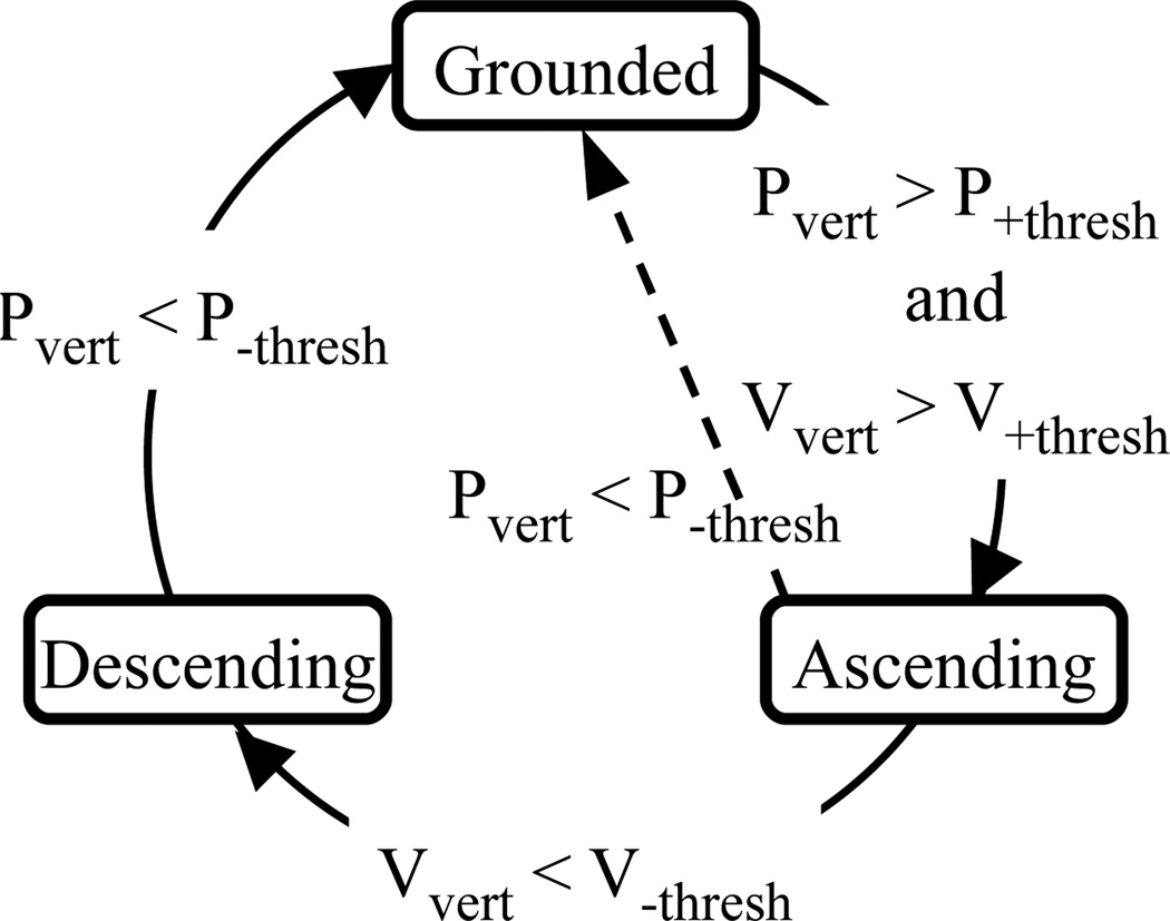
The state transition diagram for a single foot’s in-place steps. Pvert is heel height. Vvert is the heel’s vertical velocity. The current per-foot gait state (Grounded, Ascending, or Descending) is maintained unless an exit criterion is fulfilled. The dashed transition handles possible input errors: It is not a part of steady-state operation.
In our implementation, a foot is in one of three states: Grounded, Ascending, or Descending. Their steady-state transitions (Figure 9, on outside circle) define Foot Off, Max Foot Height, and Foot Strike. Foot Off occurs when the foot exceeds a vertical threshold (P+thresh) and an upward speed threshold (V+thresh). Combining both requirements permits real-world maneuvering motions while identifying in-place stepping gestures. Max Foot Height occurs when the foot’s upward velocity decreases below a threshold (V−thresh). Foot Strike occurs when the foot’s vertical position descends below a threshold (P−thresh).
The following constants – when combined with our PV-model filter’s output – have served to identify in-place-step recognition, and to permit maneuvering steps:
| (9) |
| (10) |
Mathematically, an object descends when its vertical speed becomes negative. However, our PV-model filter adds a small amount of latency, so we recognize descent before it becomes negative.
4.2 Gait Cycle Implementation
In implementing the gait cycle state machine shown in Figure 6, we required increased robustness to input errors. The dashed transitions in Figure 10 handle the following error cases:
Tracker errors: If shin tracker updates are lost, gait-state transitions may be missed. In these cases, the system returns to No Gait and awaits the next Foot-Off event.
Unexpected user input: If a user performs an unrecognizable gesture (such as keeping his foot in the air) the system returns to the No Gait state and awaits the next Foot-Off event.
The surest catch for both error cases is an over-long-state recognition algorithm: If the predicted step frequency ever falls below the threshold, the system transitions to No Gait.
Figure 10.
The UNC GUD WIP implementation’s state machine. The current state is maintained unless an exit criterion is fulfilled. The dashed transitions are for software robustness on input errors.
The step frequency measured by this state machine drives the output speed. If a user-specific frequency-to-walking-speed function were available, it could replace the generic Equation 2.
4.3 Miscellaneous Implementation
When using LLCM-WIP (Figure 7, Start-up 1), we follow its proposed algorithm [2]: Both feet’s vertical speed drives the viewpoint’s speed after being transformed (absolute valued, smoothed, offsetted, and scaled).
The GUD WIP model yields only gait-based virtual walk speeds. Virtual walking also requires a walk direction; we employ the average of the shins’ direction.
4.4 Equipment
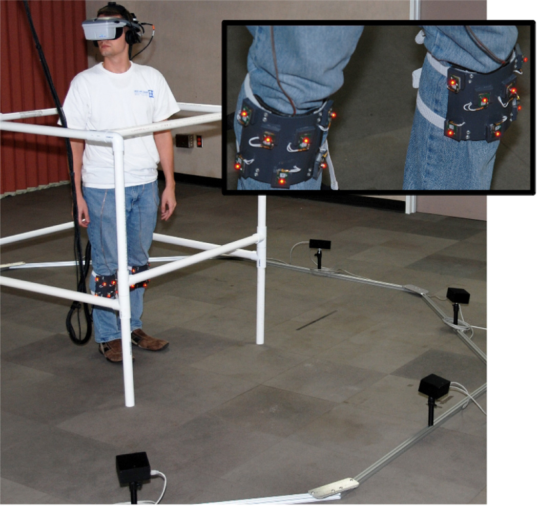
This system uses an eight-camera PhaseSpace Impulse optical motion capture system (Figure 11). Seven LEDs on a part-cylindrical plate are attached to each shin. Since three LEDs suffice for full tracking, this provides redundancy from forward views, while the curved surface enables tracking over a wide angle. The heel’s position is approximated by translating down the shin.
Figure 11.
A user within the UNC GUD WIP system. The user wears beacons for 6-DOF trackers on his shins (inset). Shin-tracking cameras surround the subject on the floor. The user’s heel position is approximated by rigid-body transform from the shin’s pose.
This in-house-coded GUD WIP implementation executes on a computer with Microsoft’s WindowsXP, an Intel Core2 2.4GHz CPU, NVIDIA GeForce 8600 GTS GPU, and 3 GB RAM. On this system, our GUD WIP implementation updates the virtual speed at approximately 1000Hz – GUD WIP’s calculations are not overly costly.
We have created a demo VE system in which users travel throughout a UNC Ackland Art Museum exhibit using the GUD WIP locomotion interface. This system employs a 3rdTech HiBall tracker and an NVIS nVisor SX head-mounted display.
5 Step-Frequency-to-Walking-Speed Evaluation
We argue that users expect specific consistent speed behaviors when really walking and that virtual walking systems should approximate those behaviors. Figure 1 visually demonstrates the speed characteristics of LLCM-WIP, GUD WIP, and Real Walking at two different frequencies. The improved smoothness – temporal consistency – visually evident when comparing LLCM-WIP’s and GUD WIP’s speeds demonstrates one important improvement provided by the GUD WIP model.
We also assert that step frequency is the most important input metric for WIP systems to measure: Users expect that the speed changes consistently with the step frequency.
We assessed the following through user study:
For each of Real Walking, GUD WIP, and LLCM-WIP, how consistent is the step-frequency-to-walk-speed?
Which of GUD WIP or LLCM-WIP is more similar to Real Walking?
We hypothesized that GUD WIP and Real Walking are consistent along this metric, and that LLCM-WIP is less consistent.
5.1 Method
Design
We performed a within-subjects, repeated-measures experiment. In each trial the user performed a walking interface (Real Walking or Walking-In-Place), stepping at one of four prescribed frequencies: 1.0, 1.5, 2.0, or 2.5 Hz. Each frequency was repeated in four trials for each interface. In all, each subject performed 32 trials. A trial for each frequency was performed before repeating a frequency. Subjects performed all trials for one interface before proceeding to the next. Interface and frequency order was assigned following Latin squares.
Participants
Eight physically unimpaired subjects performed our user study (between 19–29 years old, heights were known but lost, all male). All wore comfortable shoes, and pants which did not impair walking. Participants were paid for their time.
Procedure
After the subject was told the study’s purpose – to compare Real Walking and Walking-In-Place systems – he was set up for measurement in a stepping condition: Subjects wore a head-mounted 3rdTech HiBall-3100™ tracker when in Real Walking, our shin-mounted PhaseSpace beacons when in Walking-In-Place. In both conditions, the subject’s view of the real-world lab was unobstructed. Whether Real Walking or Walking-In-Place, the subject practiced stepping in time with a metronome set to a middle frequency (1.67Hz). The subject then performed all trials with the metronome set to the appropriate frequency. This procedure was repeated with the second interface.
In the Real-Walking condition, the subjects walked the longest distance possible in our head-tracked space (˜9m). When in the Walking-In-Place condition, subjects took in-place steps until instructed to stop (15–30 steps).
Measures
During all trials, we measured the user’s speed. For Real Walking, we calculated speed through numeric differentiation of the subject’s head-tracked position. For Walking-In-Place, we calculated his predicted virtual speed via both LLCM-WIP and GUD WIP concurrently. The experimenter did not have access to these speeds until after the subject had completed all trials.
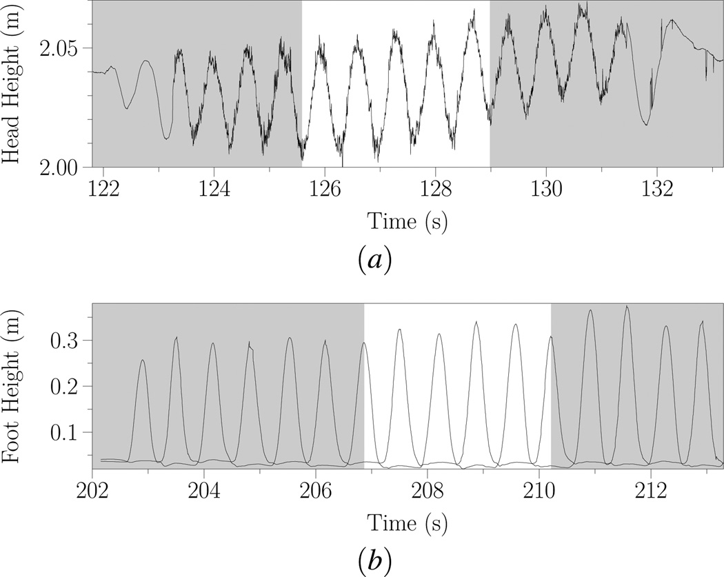
Both step frequency and speed were averaged over five steps in each condition. Five steps were identified in the Real-Walking condition as the time containing five complete head-bobbing periods (Figure 12 (a)). Five steps were identified in the Walking-In-Place condition as the time between five step’s corresponding foot heights (Figure 12(b)) – with the same period for both GUD WIP and LLCM-WIP. In both conditions, these periods were chosen for middle steps to avoid start-up or stopping effects. Furthermore, we sought good tracking and consistent stepping patterns.
Figure 12.
Five steps identified for (a) Real Walking (from the minimum head position during bobbing), and (b) Walking-In-Place (from foot position maxima). The same five-step period is used for both GUD WIP and LLCM-WIP.
While selecting the five steps, the experimenter did not look at the resulting speeds except on two or three trials when tracking errors required the experimenter to ensure that speeds had been available during some period.
Thus, for each trial, there were two measures: mean step frequency, and mean speed during that five-step period.
5.2 Analysis and Results
Five Real-Walking condition trials were lost due to system errors. No subject lost more than one trial. One subject’s data was discarded due to his inability to increase and decrease his step frequency with the metronome.
Consistency
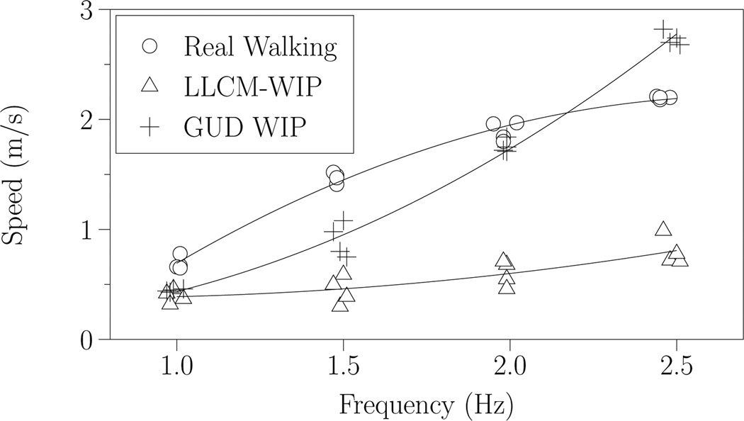
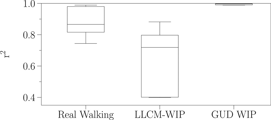
We plotted each subject’s step frequencies and output speeds (each trial providing a datapoint) for Real Walking, LLCM-WIP, and GUD WIP (Figure 13). We fitted both linear and quadratic functions to each condition’s datapoints. In all cases, the quadratic function had a higher r2 score, so we used only the quadratic fits. Real Walking and GUD WIP both exhibit high-quality fits – LLCM-WIP exhibits less (Figure 14).
Figure 13.
Results for Subject 103. Each trial provides a single data point. With four trials at each of four frequencies, we calculate a quadratic function fit for each of three conditions. Figure 14 provides the all subjects quality-of-fits.
Figure 14.
The quality of fit (r2) for the quadratic functions to the average walking speeds for each subject in each condition. Each box plot represents seven different r2 scores. GUD WIP’s (all scores ˜0.99) and Real Walking’s fits are generally quite good, but LLCM-WIP’s fit is rarely as good.
Curvature
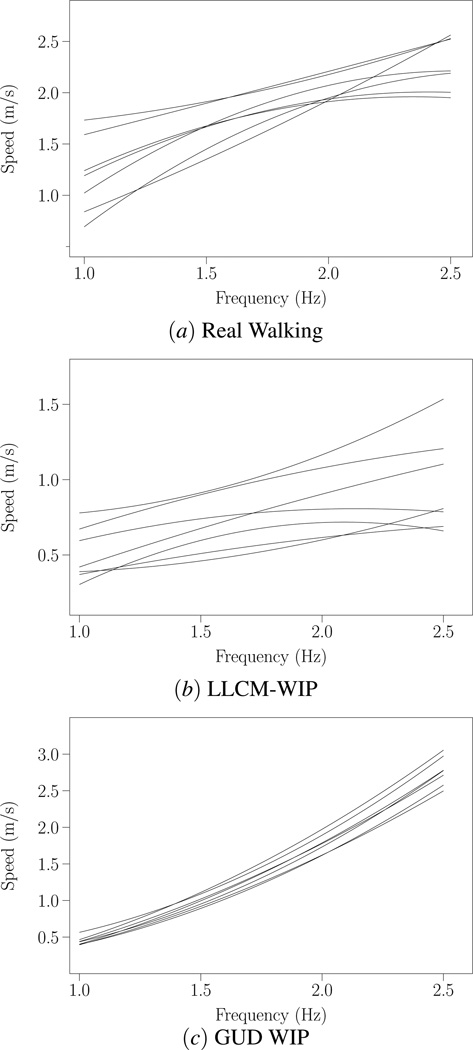
The characteristics of the Real Walking and LLCM-WIP fit functions varied considerably between subjects (Figure 15): Some subjects exhibit almost no curvature; others positive curvature; others negative. Real Walking’s curvatures ranged from −0.51–0.17. LLCM-WIP’s curvatures ranged from −0.35–0.24. GUD WIP consistently demonstrates similar curvature (0.35–0.56). A Pearson correlation found no significant within-subject correlation between Real Walking curvature and either of the virtual curvatures (Real-to-LLCM curvature correlation r = −0.561, p = 0.190; Real-to-GUD curvature correlation r = −0.166, p = 0.722).
Figure 15.
The function fits for (a) Real Walking, (b) LLCM-WIP, and (c) GUD WIP for all seven subjects from our study. Note the variation of the fits for Real Walking and LLCM-WIP: Some are nearly linear, some curve upward, some downward. There was no significant within-subject correlation of these curvature changes.
5.3 Discussion
Consistency
In Real Walking, the subjects demonstrated within-subject consistent frequency-to-walking speed (Figure 14, Real Walking data). This confirms our first hypothesis: Individuals consistently walk at the same speed when at the same step frequency. Therefore, people expect a consistent output speed from virtual walking at the same step frequency. Our second hypothesis is also confirmed: LLCM-WIP does not demonstrate high consistency; GUD WIP does.
We believe LLCM-WIP’s lower r2 fits are fundamental to LLCM-WIP’s algorithm. Since LLCM-WIP bases output speed on the vertical speed of the user’s heel, it is a function of both step frequency and step height. We found that even at consistent step frequencies, a single subject’s step heights varied (e.g., Figure 12(b)). Therefore, each step’s resulting vertical velocity would differ.
Speed Ranges
The different within-subject speed ranges visible in the three conditions (Figure 15) are unimportant. LLCM-WIP permits a user-specific multiplier for resulting output speeds. GUD WIP employed Dean’s mapping from step frequency to walking speed (Equation 2). However, a user-specific frequency-to-walking-speed function could be employed.
Neither user-specific mapping was employed herein: Finding the best per-user function would have required all Real-Walking trials and analysis to occur before virtual trials.
These mapping functions are an important difference between LLCM-WIP and GUD WIP: Had the LLCM-WIP, per-user scalar been employed, the resulting speeds for LLCM-WIP would likely have better matched Real Walking range. However, the LLCM-WIP output-speed curvatures would not have changed and would continue to show no significant correlation with Real-Walking’s curvature. Had the GUD WIP, per-user, best-fit function been used, the resulting GUD WIP curve would match Real Walking’s because GUD WIP would base its resulting speed on that curve.
Curvature
We were surprised to see the between-subject variation in Real-Walking curvatures (some positive, some negative). We wondered if some within-subject stepping pattern – for both Real Walking and Walking-In-Place – could lead to matching curvatures for both Real Walking and LLCM-WIP. However, the non-significant, negative correlation indicates that this is likely a random difference with no meaningful within-subject cause.
Not surprisingly, GUD WIP’s curvature is between-subject consistent because it based all subjects’ output speed on Equation 2. The slight variation is due to the subjects’ varying heights.
LLCM-WIP’s highly varying curvature is caused by different stepping behaviors for different subjects. LLCM-WIP’s resulting speed depends on each step’s height. We have seen that in order to reach higher WIP step frequencies, many users decrease their step height. This is what causes the negative curvatures. Zero curvature would indicate that the subject’s steps were approximately the same height at different frequencies. Positive curvature would indicate larger step heights at increased frequencies.
When performing the Real-Walking trials, many subjects appeared to shorten their stride length to match the higher frequencies. This is not the behavior described in biomechanics literature: The literature suggests that stride length and step frequency increase together with increased walking speed [4]. The nine meters available for Real Walking in our tracked space may not have permitted the subjects to acheive a consistent walking speed at the higher step frequencies. Together, these likely caused the Real-Walking function’s downward curvatures.
Employing a treadmill for future Real-Walking measurements would enable the subjects to acheive a comfortable, steady speed at any given frequency – removing the fixed-length problem.
Furthermore, we would suggest that a better Real-Walking metric could be obtained by swapping the dependent and independent variables: Treadmill-walking subjects walk at fixed speeds, and step frequency is measured. However, this is only possible for Real Walking: Virtual locomotion speed can’t be fixed to find an in-place step frequency that maches. This technique could not be used for a virtual-versus-real locomotion study.
We believe these treadmill-based techniques would result in Real Walking curves closer to those predicted by biomechanics. Nonetheless, these observations in no way invalidate this study’s results: Real Walking evidences consistent step-frequency-to-walk-speed tendencies, and – by this metric – GUD WIP is more similar to Real Walking than LLCM-WIP.
6 Future Work and Conclusions
GUD WIP provides ample opportunities for future research.
GUD WIP’s stopping latency may be unacceptable for some applications. This stopping latency is due to the ambiguity between after-last-step double support and between-two-steps double support. Further research may determine acceptable ways to disambiguate these two states. Although foot position is the same, other possible inputs may differ: head motions, nerve impulses, or muscle tensions. A less-elegant, but simple, solution would be to give the user a further input to indicate that he has stopped.
Generating the per-user functions to replace Equation 2 in our user study required significant experimenter time. This cost would make the technique untenable for production use. Since completing GUD WIP, we have discovered ways to automatically calculate a per-user step-frequency-to-walk-speed function from head position alone. A paper on this technique is in review.
The user-study analysis presented in this paper demonstrated that Real Walking and GUD WIP each provide consistent step-frequency-to-resulting-speed. We hypothesize that this consistency improves the user’s experience – leading to improved usability. We are preparing to test this hypothesis through usability comparison between LLCM-WIP and GUD WIP.
Walking-In-Place output speeds can benefit from further research. GUD WIP employs equations (Equations 2, 4, 5, and 6) from biomechanics literature from steady-state, straight-line walking. Such values may not be valid during non-steady-state periods – during acceleration, deceleration, or turns.
GUD WIP – as with most WIP systems – only accepts Walking-In-Place inputs. If a user’s gestures indicate running, our GUD WIP implementation prints an error to the screen. In our experience achieving consistent in-place running is considerably more difficult than consistent in-place walking – more so than the apparent differences between Real Running and Walking would suggest. However, VE users almost certainly wish to run through virtual environments. “Running-In-Place” systems are very research-worthy.
Even without these enhancements, GUD WIP provides a robust interface for virtual locomotion. Due to its biomechanics-informed analysis of users’ stepping gestures, GUD WIP creates forward motion more consistent with their Real-Walking experience than earlier systems. We have shown that GUD WIP generates motion that is both locally consistent (Figure 1) and step-frequency consistent (Figure 14).
Acknowledgements
We would like to thank 3rdTech for their DeltaSphere™-3000-scanned model of UNC’s Ackland Art Museum’s Plum, Pine, and Bamboo – Seasonal and Spiritual Paths in Japanese Art exhibit. It was produced using 3rdTech’s SceneVision™-3D and Innov-Metric’s PolyWorks® software. The model is copyright-protected (2004) by the Ackland Art Museum and 3rdTech, Inc.
This work was supported in part by grants from the Office of Naval Research’s VIRTE Program, NIH National Institute for Biomedical Imaging and Bioengineering, NIH National Center for Research Resources, SAIC, the NSF Graduate Research Fellowship program, and the North Carolina Space Grant program.
Footnotes
The pun is intentional: We firmly believe someone will come up with a Better WIP.
References
- 1.Dean GA. An analysis of the energy expenditure in level and grade walking. Ergonomics. 1965;8(1):31–47. [Google Scholar]
- 2.Feasel J, Wendt JD, Whitton MC. LLCM-WIP: Low-latency, continuous-motion walking-in-place. Proceedings of the IEEE 3D User Interfaces (3DUI ’08) 2008:97–104. [Google Scholar]
- 3.Finley FR, Cody KA. Locomotive characteristics of urban pedestrians. Archives of Physical Medicine and Rehabilitation. 1970;51:423–426. [PubMed] [Google Scholar]
- 4.Inman VT, Ralston HJ, Todd F. Human walking. Williams and Wilkins; 1981. [Google Scholar]
- 5.Kalman RE. A new approach to linear filtering and prediction problems. Transactions of the SME – Journal of Basic Engineering. 1960;82:35–45. [Google Scholar]
- 6.Molen NH, Rozendal RH. Some factors of human gait. Koninklijke Nederlandse Akademie van Wetenschappen. 1966;69:522–527. [PubMed] [Google Scholar]
- 7.Molen NH, Rozendal RH, Boon W. Fundamental characteristics of human gait in relation to sex and location. Koninklijke Nederlandse Akademie van Vetenschappen. 1972;75:215–223. [PubMed] [Google Scholar]
- 8.Murray MP, Drought AB, Kory RC. Walking patterns of normal men. Journal of Bone and Joint Surgery. 1964 Mar;46-A(2):335–360. [PubMed] [Google Scholar]
- 9.Murray MP, Kory RC, Clarkson BH, Sepic SB. Comparison of free and fast speed walking patterns of normal men. American Journal of Physical Medicine. 1966;45(1):8–24. [PubMed] [Google Scholar]
- 10.Murray MP, Kory RC, Sepic SB. Walking patterns of normal women. Archives of Physical Medicien and Rehabilitation. 1970;51:637–650. [PubMed] [Google Scholar]
- 11.Öberg T, Karsznia A, Öberg K. Basic gait parameters: Reference data for normal subjects. Journal of Rehabilitation Research. 1993;30(2):210–223. [PubMed] [Google Scholar]
- 12.Razzaque S, Swapp D, Slater M, Whitton MC, Steed A. Redirected walking in place. In: Mueller S, Stuezlinger W, editors. Proceedings of the 8th Eurographics Workshop on Virtual Environments. 2002. pp. 123–130. [Google Scholar]
- 13.Slater M, Steed A, Usoh M. The virtual treadmill: a naturalistic metaphor for navigation in immersive virtual environments. Selected papers of the Eurographics workshops on Virtual Environments ’95. 1995:135–148. [Google Scholar]
- 14.Templeman JN, Denbrook PS, Sibert LE. Virtual locomotion: Walking in place through virtual environments. Presence. 1999 Dec;8(6):598–617. [Google Scholar]
- 15.Usoh M, Arthur K, Whitton MC, Bastos R, Steed A, Slater M, Brooks FP., Jr . Proceedings of the 26th annual conference on computer graphics and interactive techniques (SIGGRAPH ’99) New York, NY, USA: ACM Press/Addison-Wesley Publishing Co; 1999. Walking >walking-in-place >flying, in virtual environments; pp. 359–364. [Google Scholar]
- 16.Welch G, Bishop G. Technical Report TR 95-041. Chapel Hill, NC: Department of Computer Science, University of North Carolina at Chapel Hill; 2006. Jul, An introduction to the Kalman Filter. 27599-3175. [Google Scholar]
- 17.Whitton MC, Cohn JV, Feasel J, Zimmons P, Razzaque S, Poulton SJ, McLeod B, Brooks FP., Jr Comparing VE locomotion interfaces. Proceedings of the IEEE Virtual Reality 2005. 2005 Mar;:123–130. [Google Scholar]
- 18.Yan L, Allison RS, Rushton SK. New simple virtual walking method - walking on the spot. 8th Annual Immersive Projection Technology (IPT) Symposium Electronic Proceedings. 2004 [Google Scholar]
- 19.Zarrugh MY, Todd FN, Ralston HJ. Optimization of energy expenditure during level walking. European Journal of Applied Physiology and Occupational Physiology. 1974;33:293–306. doi: 10.1007/BF00430237. [DOI] [PubMed] [Google Scholar]


