Abstract
Purpose
Head motion continues to be a major source of artifacts and data quality degradation in MRI. The goal of this work was to develop and demonstrate a novel technique for prospective, 6 degrees of freedom (6DOF) rigid body motion estimation and real time motion correction using inductively coupled wireless nuclear magnetic resonance (NMR) probe markers.
Methods
Three wireless probes that are inductively coupled with the scanner’s RF setup serve as fiducials on the subject’s head. A 12 ms linear navigator module is interleaved with the imaging sequence for head position estimation, and scan geometry is updated in real time for motion compensation. Flip angle amplification in the markers allows the use of extremely small navigator flip angles (~1°). A novel algorithm is presented to identify marker positions in the absence of marker specific receive channels. The method is demonstrated for motion correction in 1 mm3 gradient recalled echo experiments in phantoms and humans.
Results
Significant improvement of image quality is demonstrated in phantoms and human volunteers under different motion conditions.
Conclusion
A novel real time 6 DOF head motion correction technique based on wireless NMR probes is demonstrated in high resolution imaging at 7 Tesla.
Keywords: prospective rigid body motion correction, inductively coupled probes, wireless NMR markers
INTRODUCTION
Magnetic resonance imaging (MRI) stands today as one of the most widely used imaging modalities in the noninvasive investigation of body structure and function. Subject motion however continues to be a persistent problem in MRI. Scanner field strengths of 3 Tesla and higher have enabled neuroimaging studies at sub-millimeter resolutions. However, at these high resolutions, motion of even a few millimeters degrades data quality severely and nullifies the benefits of expensive high field MRI.
Existing motion correction techniques in MR may be broadly categorized into post-processing based retrospective (1–9) or real time prospective methods (10–19). Although, retrospective methods are more routinely used, they suffer from some drawbacks, which can be overcome effectively by prospective correction. Chiefly, retrospective methods fail to correct for the effects of through-plane motion arising from movement of spins in and out of the excited slice plane in 2D imaging. Additionally, retrospective methods do not correct for the edges of the volume of interest moving out of the imaged volume as well as sampling density inconsistencies in the acquired data. Prospective correction methods overcome these weaknesses by updating the imaging geometry in real time to compensate for the subject motion, keeping the imaging volume fixed with respect to the anatomy of interest.
Prospective motion correction techniques differ primarily in their approach to estimating the motion in real time. Navigator-based methods rely on correlating rapidly acquired projections to measure the position of the anatomy. Several navigator trajectories have been developed over the years targeting pure translations (1,2,11), pure rotations (3,12,14), as well as compound 3D six degrees of freedom (6DOF) motions (4,15). 2D spiral navigator trajectories combined with image-based tracking has been demonstrated at 1.5 Tesla (16). Another class of method relies on volume registration of sequentially acquired image volumes for estimating the motion parameters in real time (17). Motion correction using optical tracking of reflective markers has demonstrated high performance in real time head motion correction (18–22). Optical systems require considerable calibrations and hardware additions including an RF shielded camera operating inside the bore and a direct line of sight with the subject’s head, which is not always available.
Use of NMR probes to detect motion was demonstrated as early as 1986 by Ackerman et al (23). Since then, NMR probes have been used for motion detection extensively in interventional MR applications such as catheter tip tracking (24–26) and MR guided surgical interventions (27, 28). Application of probe technology to correct for head motion in MR was first demonstrated by Derbyshire et al. in 1998, where inter-image head motion in six degrees of freedom was corrected prospectively (13). Recently, NMR probes based on full 6DOF prospective, interview motion correction was demonstrated in brain imaging at 1.5 Tesla (29,30). In this work, rapid three axis linear navigators were interleaved with the imaging sequence to locate three active markers mounted on a headband worn by the subject. The marker locations were then used to estimate the motion parameters relative to the initial head position and prospectively update the scanning geometry.
In the context of motion tracking, NMR probes have often been considered ‘active markers’ since they have current carrying connections to the scanners receive system. Concurrently, markers have also been developed that do not have cable connections and simply consist of an LC circuit tuned to the scanner’s resonant frequency. These markers, known as ‘semi-active markers’, interact with the MR’s transmit-receive system via inductive coupling. Inductive coupling results in an effective flux and flip angle amplification inside the marker by a factor of the Q (quality factor) value of the marker (31). As a result, high signal to noise is generated in the marker for very low flip angles (~1°), which allows accurate localization against large background objects. Semi-active markers have been effectively utilized in interventional MR for tracking of catheters and surgical devices in MR (31–37). The benefits of motion tracking with semi-active markers are manifold. Firstly, since semi-active markers are wireless, they eliminate the need for spare receiver channels. This is a serious limitation of active marker based motion tracking, especially when high channel-count receive arrays are used and spare channels are unavailable. Secondly, since the markers couple to the receive system inductively, the need for matching capacitors and cable connectors is eliminated. This enables reducing the size of the markers significantly, increasing patient comfort and positioning flexibility. Furthermore, it increases the flexibility of marker placement while eliminating the possibility of cable currents and associated susceptibility effects in the image. Semi-active markers are therefore ideally suited for real time multi-axis head motion correction.
In this article, we present the development and application of prospective real time correction of head motion in 6DOF using inductively coupled semi-active markers. We demonstrate the real time motion correction on a whole body 7 Tesla scanner, although the method is generally applicable across field strengths. A linear navigator sequence is used to locate the 3D positions of three tuned semi-active markers rigidly mounted on the head in real time. In the absence of marker specific channel data, an algorithm for estimating the position of the triangle formed by three markers from single channel projections is presented. Marker and system performance is characterized with respect to varying amounts of translations, rotations, navigator flip angle and marker orientation with respect to the static magnetic field, B0. A least square’s error minimization formulation presented in Umeyema et al (29,38) is used to estimate motion parameters in real time and to update scan geometry to track head motion. Real time motion correction is demonstrated in high-resolution gradient recalled echo (GRE) and magnetization prepared rapid gradient echo (MPRAGE) imaging in phantoms and human volunteers.
METHODS
Marker Construction
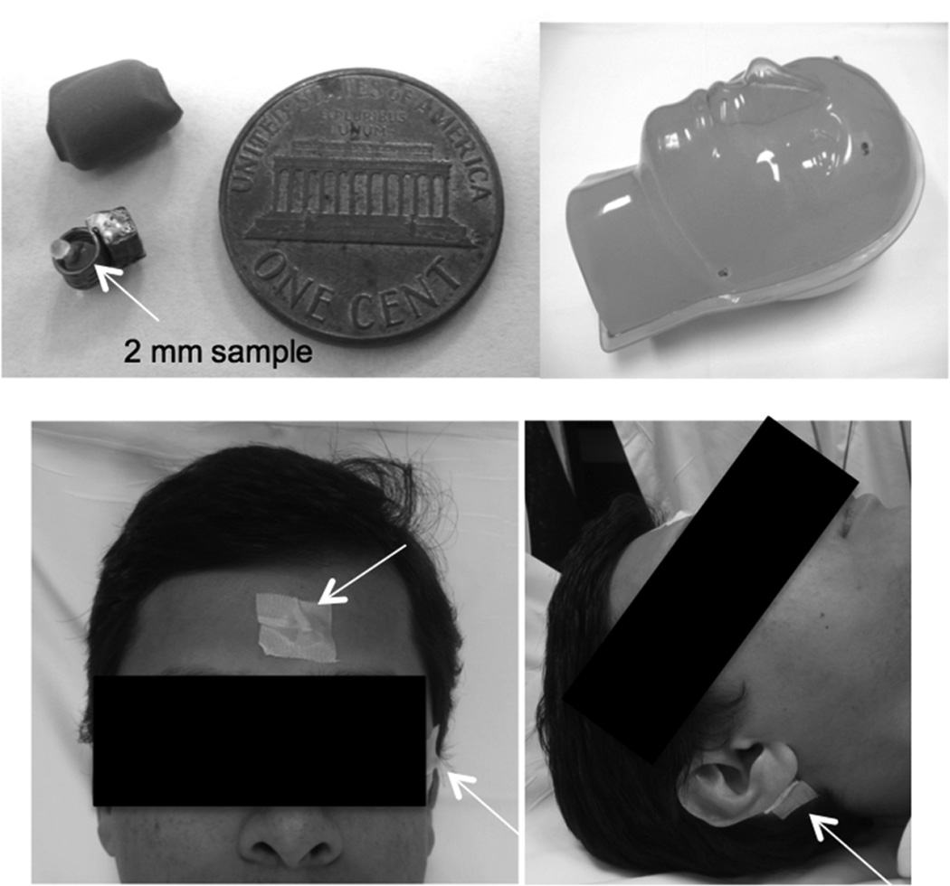
Three semi-active markers, each consisting of a solenoid inductor with a sample cell and a tuning capacitor were constructed for the 298 MHz system (Figure 1a). The inductor had 5 turns of 26 gauge enameled copper wire wound to an internal diameter of ~2 mm. The Q factors of the markers were measured to be ~60. The marker’s sample cell was a 2/1.5 mm outer/inner diameter spherical glass bulb fabricated from a 1/0.8 mm outer/inner diameter glass capillary (World Precision Instruments, Inc, FL, USA). For constructing a spherical bulb from a capillary, one end of the tube was applied to a flame until the melting glass sealed the end. Following this, the other end of the tube was applied to the flame and rotated at the same time, causing it to seal and bulge into a hollow sphere of ~2 mm outer diameter. Using a file, the tube was scored at the neck of the sphere and broken off yielding a hollow sphere with an opening to fill the sample. Distilled water doped with 25 mM Gd was injected into the sphere to serve as the sample. The sphere was sealed with two-part 5-minute epoxy. The sphere was then set inside the solenoid and enclosed in a double layer of rubber shrink wrap tubing yielding an insulated capsule of approximately 6 × 4 × 3 mm3 shown in Figure 1a.
Figure 1.
(a) Wireless NMR marker with inbuilt sample before and after insulation. (b) Markers on a head shaped phantom (c) Mounting of probes on a human volunteer.
Motion Estimation and Geometry update
All experiments were performed on a whole body 7 Tesla MR scanner (Philips Healthcare, Cleveland, OH, USA) with a volume transmit coil and a 32 channel receive head coil. (NOVA Medical Inc, Wilmington MA, USA).
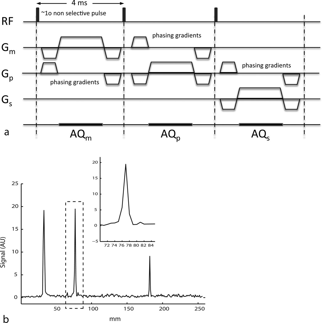
Figure 2a shows a three-axis navigator sequence interleaved with the imaging module used for locating the markers along the measurement, phase and slice axes. The navigator consisted of 1° non-selective block excitation pulses followed by a balanced, high-bandwidth projection readout. The TR of the navigator was 4 ms, translating into a 12 ms total navigator time. An important modification to the sequence was the addition of phasing gradients (4 mT/m, 3.58e-3 s·mT/m area) in an orthogonal axis before the individual projection readouts to reduce signal contributions from large background objects like the head (10). Navigator data was acquired using the Volume transmit/receive coil in the system. Figure 2b shows an example of a navigator magnitude in the anterior posterior direction from a human volunteer.
Figure 2.
(a) Navigator sequence employed for 3D localization of NMR probe markers. The total time of the sequence is 12 ms. (b) Example navigator magnitude data in the anterior posterior direction acquired in a human volunteer scan.
Marker identification in 3D space
The navigator raw data along the three directions were extracted in real time and Fourier transformed using the spectrometer’s real time data processing functionality. The spatial domain magnitude data were then analyzed in a multistep algorithm for locating the three marker peaks along each direction:
- Step 1. Identifying marker positions along individual projections
-
1.1A recursive peak finding algorithm in which a peak was identified as the maximum value along the projection, followed by zeroing of that and the two nearest neighbor points was executed until three distinct peaks were found in the projection. To obtain sub-pixel marker localization, the final locations of the markers were extracted by performing a parabolic fit to the peaks and two nearest neighbor points (prior to zeroing), and finding the location of the maxima. Markers along each projection were indexed in the order of identification.
-
1.2To improve the robustness of the algorithm, the initial placement of the markers was made such that the difference between side lengths of the triangle formed by the markers was greater than 5 mm. Also, at any sampled time point, if any two-marker projection peaks along an axis were within 10 mm of each other, motion correction was not performed for that view.If the current phase encode is the first in the scan, the marker peak locations extracted are used to define the reference triangle to be tracked and measure its side distances, drefi. For this calculation, the three indexed maker peaks from each navigator direction are combined in sets of three to yield the location of the three probes i.e., as {x1, y1, z1}, {x2, y2, z2} and {x3, y3, z3}. For the first phase encode, steps 2 to 3.2 are skipped.
-
1.1
- Step 2. Identifying all possible marker triangles in 3 D space.
-
2.1The three marker positions from the three projections can be backprojected under the condition that every reconstructed point have one coordinate from each projection. This process yields a grid of 33 = 27 points in 3D space. These cluster of points represent the set of all possible vertices of the current position of the triangle formed by the markers rigidly fixed to the head.
-
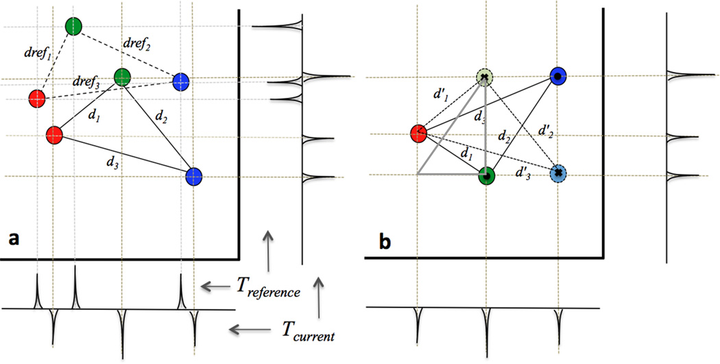
2.2From the backprojected set of 27 points, 2925 triangles in 3D space can be formed using combinations of 3. Furthermore, a condition that none of the projection peaks be omitted in any triangle allows the elimination of a majority of the triangles from the possible solution set, thus reducing it to only 36 possible triangles which can be pre-indexed. For example, the triangle shown in grey in Figure 3b belongs to the set of 2925 triangles, but does not contain at least one projection coordinate and hence cannot be the solution triangle. With the marker peaks along each direction indexed from 1 to 3, the indices of the vertices of all the 36 possible triangles were listed according to a preloaded 36 × 9 array (Appendix A).
-
2.1
- Step 3. Identifying current position of marker triangle.
-
3.1For each of the 36 triangles, three side lengths di were computed from the vertices positions. An initial selection of the solution triangle was based on the assumption that for rigid body motion, the difference in side lengths di from the reference triangle drefi computed from the first set of navigator projections in the scan would be the minimum. Although this assumption does not hold true universally due to noise in the marker localization, it provides an initial condition to identify the correct solution. Hence, for each triangle, six different side length error values (dErrn) were computed as below
where n = 1 to 6, a,b,c = 1 to 3 and a ≠ b ≠ c.(1) Computing six different dErr values accounted for the possibility of vertex swapping in the identified triangles. The minimum of the dErr values (dErrmin) for each triangle was taken to be the best possible side length match for that triangle. -
3.2From the list of the 36 triangles, the triangle with the minimum dErrmin was accepted as the first estimate of the current position of the probe triangle. Figure 3a shows an example of a marker triangle with projections along two dimensions at two different time points.
-
3.3Even though the correct marker triangle may be identified at the end of step 3.2, the marker indices assigned in step 2.2 may in fact not correspond correctly to indices assigned in the initial reference projections. This will occur when the marker peaks swap indices along any axis due to fluctuating marker signal intensities. To identify correct marker positions relative to the reference projections, triangle vertices are swapped in the solution triangle in accordance to the side distance measures, so that d1(and dref1) is always the distance between vertex 1 and 2, d2(and dref2) is always the distance between vertex 2 and 3 and d3(and dref3) is always the distance between vertex 3 and 1.
-
3.1
- Step 4.
-
Identification of the triangle in step 3 does not necessarily guarantee the correct assignment of the individual probe coordinates. Erroneous solutions can arise as a result of either the side lengths being nearly equal or due to reflections in one or more directions leading to coordinate swapping between points yielding a minimum dErrmin while maintaining the side length order, as shown in Figure 3b. To confirm the accuracy of the triangle solution identified in Step 3.3, we rely on the change in handedness of the triangle, described by the normal vector of the triangle.Three side vectors are estimated, going from the shortest side length to the longest (d⃗1, d⃗2, d⃗3). For the identified triangle, the cross product between any two side vectors taken in order of increasing length gives the normal vector of the triangle
In the event of a coordinate swapping (reflections in one or more coordinates), the triangle normal changes direction as the handedness of the triangle changes. The angle between the initial marker triangle normal calculated from the first navigator acquisition and N⃗ is calculated using a dot product rule(2)
Since the marker triangle is moving in space, the normal vector can change directions even without the occurrence of coordinate swapping. To account for this we set a relatively relaxed |θ| threshold value of 45° above which the identified triangle is rejected. The triangle is removed from further consideration and steps 3.2 to 4 are repeated until a triangle is found which passes the criterion.(3)
-
Figure 3.
a: 2D example of a marker triangle in space. Projection peaks along the two axes are back projected and the triangle with minimum side distance (di) change from the initial reference side distances (drefi) is identified as a solution. b. Example of coordinate swapping during backprojection (y coordinate swapped between green and blue markers) leading to an erroneous reflected triangle (in bold) being identified as the initial solution instead of the correct triangle (dotted). Direction of the triangle normal represented by a ✖ for going into and • for coming out of the plane is however reversed allowing for rejection of this solution. Triangle in gray shows an example of a triangle from among the 2925 triangles, which is not in the subset of 36 possible triangles as it misses at least one projection.
Rotations about the three axes were estimated from R and as a final check, if the absolute values of any of the three rotation angles or the three translational shifts exceed 45° or 45 mm respectively, the solution was deemed incorrect and steps 3.2–5 are repeated. In case of the above criterion remaining unmet for two executions of step 5, no motion correction was performed for that particular shot. The maximum number of executions of steps 3.2 – 5 was limited to 5.
Validation of marker identification algorithm through simulation
In order to test the robustness of the above algorithm, simulations were performed in MATLAB (Mathworks Inc, MA, USA). Three points were randomly generated within a specified field of view to represent the original locations of the markers. To this set of three points, randomly generated 6DOF rotations and translations within < ±25 degrees and < ±25 mm were applied to yield ‘current’ locations of the markers. Random noise with mean of 0 mm and standard deviation of 1 mm was added to coordinates of these points to represent the error in marker localization. The resulting coordinates were taken as the projection peaks along the three directions and the marker triangle was extracted using the described algorithm. To verify the accuracy of the solution, the reconstructed marker locations compared to the ‘current’ locations. The simulation was performed 20,000 times and error rate of the algorithm was measured as the number of incorrect solutions/20,000. For the correct solutions, the number of incorrectly identified triangles prior to arriving at the correct solution was also recorded.
Geometry update
Head position at the first ky line was assumed to be the reference position relative to which motion at all subsequent phase encodes were estimated. Following motion estimation, the scan geometry parameters were updated before the next imaging excitation for prospective slice tracking. To correct for translations, the phase and frequency factors of the data acquisition and the excitation frequency of the RF were updated. To account for the rotations, the gradient orientation matrix was updated using the estimated rotation matrix.
Marker Characterization
Flip angle amplification effect in the markers ensures high marker to background contrast for very low excitation flip angles, of the order of 1°. This contrast however reduces for higher flip angles that increase background signal and may decrease marker signal once the amplified flip angle (nominal flip angle * Q) exceeds 90°. The signal from the markers is therefore highly dependent on factors such as orientation with respect to the B0 field and the excitation flip angle. Since the accuracy and precision of the motion correction system can be assumed to be a function of marker signal, both of these factors ultimately contribute to overall system performance. Phantom experiments were performed in order to characterize marker performance with respect to the two above factors.
Marker signal and system precision dependence on orientation
To measure the change in marker signal with orientation with respect to B0, a marker was fixed to a rotary holder and mounted on a CuSO4 bottle phantom placed near the isocenter. The marker was initially positioned such that the solenoid axis was perpendicular to B0, either along the left-right axis or the anterior posterior axis. For the first experiment, the marker was placed on top of the phantom, and in the second experiment it was placed on its left. In the two sets of experiments, the orientation of the markers was stepped through 10c increments about the anterior-posterior or the left-right axis until the solenoid axis was parallel to B0. For every angle, a gradient echo sequence with the navigator (1° non selective flip angle, 1 mm readout resolution, 256 × 256 matrix, TR/TE = 25/4 ms) was performed.
Following identification of the marker peak in the magnitude data and zeroing of the two nearest neighbor points, an estimate of background signal amplitude was calculated as the average of the pixel intensities of the central 1/3rd of the field of view, which contained the background phantom. A marker-to-background contrast (MBC) parameter was calculated for identified peak as
| (4) |
to quantify marker conspicuity. Additionally, the standard deviation of the marker position over the phase encodes was calculated to quantify the variation of marker localization precision with changing orientation of the marker.
Marker signal dependence on navigator flip angle
To quantify the change in marker signal and MBC with excitation flip angle, three markers were placed on a head shaped CuSO4 phantom as shown in Figure 1b with their axes along the anterior posterior axis, orthogonal to B0. A long TR GRE sequence to minimize T1 effects (1 × 1 × 1 mm3 voxel size, 256 × 256 matrix, TR/TE = 500/4 ms) with a 3D linear navigator was performed with navigator flip angles ranging from 0.2° to 6° in steps of 0.4°. Individual marker signal and MBC values were calculated for the range of flip angles from navigator magnitude data. The flip angle that presented maximum marker signal and MBC values was selected for all subsequent motion correction experiments.
Safety
In the absence of active detuning of the markers, it was important to asses marker safety prior to use in human experiments. We used a fiber optic temperature probe (FISO Technologies, Canada) to record temperature change of the three markers under three RF intensive sequences.
Low Flip Angle 3D GRE, TR/TE = 51/2 ms, FA = 10°, 20 repetitions, Total Time (Taq) = 13 min 26 s, Average RF power = 86 watts.
High Flip Angle 3D GRE, TR/TE = 51/2 ms, FA = 90°, 20 repetitions, Taq= 13 min 26 s, Average RF power = 277 watts.
3D Fast Spin Echo, TR/TE= 1161/59 ms, FA = 90/150°, 10 repetitions, Taq = 15 min 31 s. Average RF power = 350 watts.
The markers were placed with solenoidal axes perpendicular to B0 to maximize coupling with the B1 field. The temperature probes were fixed to the solenoidal surface of a markers and the temperature was recoded every 1-second. A baseline temperature recording was acquired for 30 seconds prior to sequence start.
System Accuracy and Precision
To evaluate system accuracy and precision, synthetic motion was simulated on a stationary head shaped CuSO4 phantom with three markers mounted as shown in Figure 1b. Modifications in the pulse program allowed the user to load in arbitrary 6 DOF motion patterns from a text file and modify the scanning geometry accordingly in each ky line during the scan. To simulate translations, the frequency and phase factors of the acquisition and RF excitation frequency were updated. To simulate rotations, the gradient matrix was updated in real time. With the knowledge of the expected and observed 3D probe locations, measures of individual probe as well as complete system accuracy and precision could be extracted. Although simulated translations and rotations are strictly speaking not equivalent to true measures of system performance, they do provide an easy way of evaluating marker performance under the best case scenario while helping to diagnose errors in implementation. Also, validation with rigid body motions simulated by the scanner pulse sequence alleviate the need for expensive and cumbersome motion phantoms
To measure accuracy and precision under simulated translational motion, three GRE scans were performed with simulated translations in each of the X, Y and Z scanner directions (Navigator TE/TR = 1.4/4 ms, 256 data points, 1 mm resolution, flip angle = 1°, readout bandwidth = 807 Hz/pixel, 2 signal averages). In each scan, a total number of 512 phase encodes were stepped through 9 positions (−20 mm to 20 mm, 5 mm increments) along the axis, with ~56 profiles per offset. The 3D Euclidean distance of each extracted probe location from the expected location was calculated as localization error. The accuracy and precision of the probes at each location were then estimated as the mean and the standard deviations of these localization errors over the ~56 measured profiles. Additionally, overall system translational and rotational errors for every profile were calculated, which yielded the system accuracy and precision measures under translations. A similar procedure was followed for rotations along the three axes, with angular offsets ranging from −10° to 10° degrees in 2° increments.
Motion Correction Experiments
All human volunteers provided informed written consent and were scanned under an institutional IRB approved protocol.
Phantom Experiments
For initial testing of the motion correction system we employed a bundle of corn to serve as a rigid body phantom. Corn provided very fine structural detail comprising of individual kernels (~3–4 mm size), germs inside the kernels (~1–2 mm) as well as air gaps between the kernels (~1 mm). Also, corn did not present any major susceptibility artifacts. It therefore served as an ideal high-resolution motion phantom presenting fine structural detail. Three markers were mounted on the bundle. High-resolution GRE scans with 1) stationary and 2) manually induced step rotations about the foot head axis were performed on the bundle to test the motion correction system (1 mm3 voxel, 256 × 256 matrix, TR/TE = 100/4 ms, Taq= 24 s, single axial slice). All scans were performed with and without prospective motion correction.
Human Experiments
Motion correction in humans was implemented in 3D T1 weighted magnetization prepared rapid gradient echo (MPRAGE) sequence and in high resolution 2D T2* weighted GRE on the 7 Tesla scanner. Two adult volunteers (one male and one female) were scanned.
The following scan parameters were employed for the MPRAGE sequence on the male volunteer : 1 × 1 × 2 mm3 resolution, 256 × 256 matrix, 20 axial slices, readout direction: anterior-posterior, 60 shots (factor = 40), shot duration = 1135 ms, Inversion delay = 1000 ms, TR/TE = 4.8/2.3 ms, flip angle = 7°, Navigator flip angle = 2.3°). The navigator was acquired just prior to the inversion pulse. Markers were mounted non-collinearly on the human volunteer with medical tape as shown in Figure 1b. The volunteer was instructed to perform three patterns of motion during the scans: 1. Keep the head still during the scan to assess the case where no conscious motion is performed; 2. Nodding motion in the left–right direction and 3. Nodding motion in the foot-head direction. The motions ranged within ±6° rotations and ±4 mm translations, which produced significant corruption of images without motion correction.
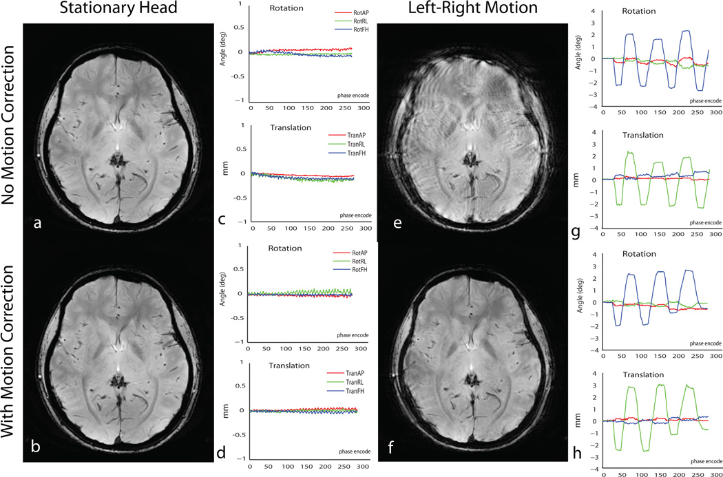
The T2* weighted GRE scan was acquired with the following parameters for the female volunteer: 0.8 mm×0.8 mm inplane resolution, 3 mm slice thickness, 1 slice, TR/TE = 400/12 ms, flip angle = 40°, Taq = 1 minute 49 seconds, Navigator flip angle = 1 °). The navigator was applied once per TR. The volunteer was instructed to move the head continuously in the left–right direction and scans were performed with and without motion correction.
Quantitative evaluation of image quality
To quantitatively evaluate the impact of prospective motion correction on image quality, measures of normalized image gradient entropy of the uncorrected and corrected images were calculated (39). Presence of motion artifacts in images was expected to increase the normalized gradient image entropy closer to a value of 1 (expected for a flat image). Normalized image entropy equals 0 for an image containing a single nonzero point. Sharper images generally have a gradient image with lower image entropy.
RESULTS
Robustness of Marker Identification Algorithm
Out of 20,000 trials with randomized marker positions and motions, the correct marker triangle was identified 19621 times (highest iteration count recorded from all 20,000 trials was 20), giving a sensitivity of 98.11 %. The correct solution was found in the first pass through the list of 36 triangles in 16974 runs and within 5 passes in 19614 (98.07%) trials. Similar sensitivity scores with 5 passes and a the maximum 36 passes suggest that increasing the number of search iterations to more than 5 may not be beneficial. We therefore limited the number of search iterations to 5 in our actual implementation. Table1 summarizes the distribution of the number of passes required for the algorithm to arrive at the correct solution. The algorithm identified an incorrect solution triangle in 379 runs.
TABLE 1.
Simulation run results of the probe triangle detection algorithm. Out of 20,000 runs, a total of 98.11% of runs resulted in the correct triangle location identification. When the number of passes through the list of 36 possible triangles is limited to 5, 98.07% (19621/20000) runs resulted in the correct solution. The simulation was run with very liberal values of random point generation in space, random normal noise addition (μ = 0 mm, σ = 1 mm), random combined multiaxis rotations within ±25° and multiaxis translations within ±25 mm.
| Total 20000 Runs | ||||
|---|---|---|---|---|
| # of searches through 36 triangles for arriving at a solution |
# of runs arriving at a solution at every searchcount |
# of correct solutions |
# of incorrect solutions |
Cumulative % of correct solutions |
| 1 | 17259 | 16974 | 285 | 84.87 |
| 2 | 2374 | 2299 | 75 | 96.37 |
| 3 | 238 | 232 | 6 | 97.53 |
| 4 | 104 | 97 | 7 | 98.01 |
| 5 | 12 | 12 | 0 | 98.07 |
| >5 | 13 | 7 | 6 | 98.11 |
| 20000 | 19621 | 379 | 98.11 | |
Overall, the algorithm was found to be sufficiently robust in the presence of synthetic marker localization noise in marker positions (μ = 0 mm, σ = 1 mm), random point generation in space, random combined multiaxis rotations within ±25° and multiaxis translations within ±25 mm.
Marker Characterization: Dependence on Orientation
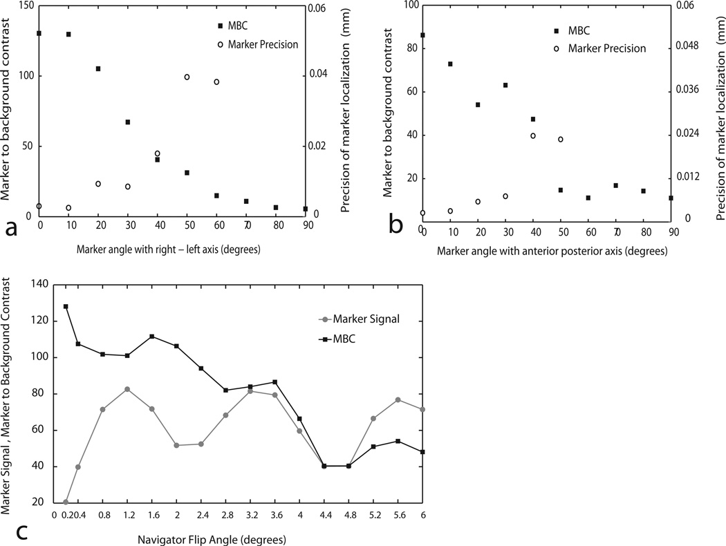
MBC was observed to change significantly with orientation with respect to B0. Figures 4a and 4b shows the variation of the MBC value with orientation angle of the marker, starting from the orthogonal axial positions, ending at alignment with B0. The MBC values decrease with increasing alignment of the marker axis with B0. This is as expected since decreasing amount of flux couples with the solenoid as the marker is increasingly oriented towards B0. For marker orientations of <30°, MBC was seen to remain high allowing marker localization with submillimeter precision (shown in gray data points). Above orientation angles of ~40°, marker precision decreased significantly, essentially due to background points being identified as marker in multiple phase encodes. Such severe rotations are however typically not observed in human experiments. For all human experiments, the markers were placed with the solenoid axes along the anterior posterior or right left axis.
Figure 4.
Results of marker characterization (a & b) Variation of maker to background contrast (MBC) and marker localization precision with marker orientation with respect to right–left axis (4a) and the anterior–posterior axis (4b). Precision data points are shown only for angles where precision was < 1 mm. (c) Variation of marker signal and MBC on navigator flip angle.
Marker Characterization: Dependence on Flip Angle
Figure 4c shows the change in signal and MBC of a marker with flip angle in the range of 0.2° to 6°. An approximately sinusoidal pattern is observed in the absolute signal with increasing flip angle of excitation. The sinusoid half period span of ~2.4° yields a Q factor of 180/2.4 = 75 which is close to the measured Q of the coil, verifying the flip angle amplification effect. The MBC of the marker was seen to reduce almost monotonically with increasing flip angle. To maximize both marker signal and MBC, 1° was chosen as the navigator excitation angle for all motion correction experiments. Difference in MBC values from the previous experiment demonstrated the usefulness of the phasing gradients in reducing the background signal.
Marker Characterization: Safety Tests
Temperature for all markers under all sequences, i.e. the low and high FA 3D GRE and 3D TSE, did not rise above noise levels of the pre-sequence baseline temperature (0.04° Celcius calculated as the standard deviation value) at any point during the three sequences tested. The markers did not feel warm to touch at any point during or after any of the above sequences.
System Accuracy and Precision
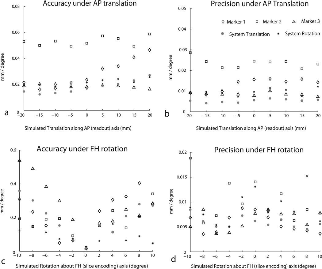
Figure 5a shows the measured accuracy and precision of the three individual markers and as well as the compete system under readout direction (anterior-posterior) translation. Individual markers were located within a maximum of 70 µm for all ranges of motions applied. The precision of marker localization was under 30 µm universally. For the overall system, the accuracy of measuring translations was under 30 µm for the range of offsets while the precision was under 10 µm. The accuracy of rotations (expected to be all zeros) estimated for the whole system was under 0.03° and precision was under 0.015°.
Figure 5.
Accuracy and precision measurements of the individual markers and the complete motion detection system measured using synthetic readout direction translations (a&b) and foot head axis rotation (c&d) experiments.
Figure 5b shows similar data for rotation about the slice (foot-head) axis. Marker and system accuracy were considerably worse than those measured under translation motion. Individual markers were located within a maximum of 600 µm for all ranges of rotations applied. The precision of marker localization was under 20 µm universally. For the overall system, the accuracy of measuring translations was under 400 µm for the range of rotations while the precision was under .015 µm. System rotational accuracy was under 0.2° and precision was under 0.02°. Accuracy and precision measurements from other motion patterns (data not shown) fell in a similar range. The performance metrics estimated in the above experiments give the ‘best case’ scenarios since motion was only simulated.
Motion Correction Experiments
Phantom Motion
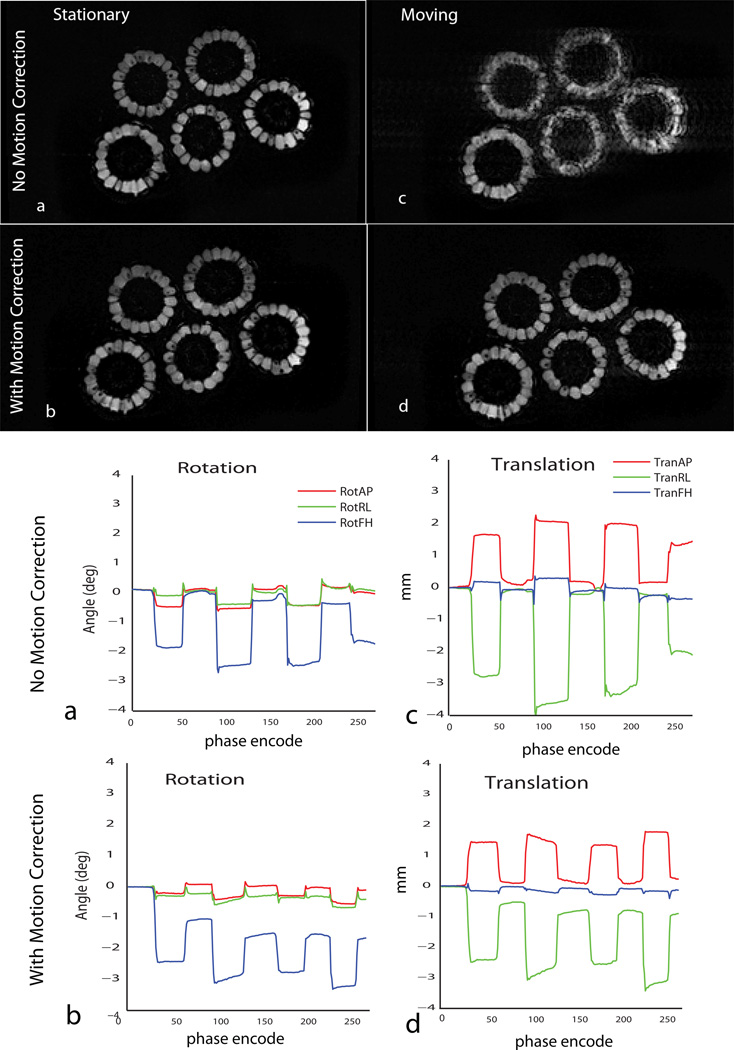
Figures 6 a–d show the results of motion correction in GRE imaging of the corn bundle. Rows 1 and 2 show the images acquired without and with motion correction while columns 1 and 2 show the stationary and moving cases. Figure 6 e–h show the motion patterns induced in the bundle. In the case where no motion is induced, image quality is maintained when motion correction is turned ON. In the motion case, the image is severely corrupted when motion correction is not applied. With real time motion correction ON, image quality is restored and is comparable to the no motion cases. Individual corn kernels are clearly evident, along with the air gaps between the kernels and the germs inside. Image quality metric calculated as the normalized entropy of the gradient image changed from 0.4194 to 0.3672 for the motion case, verifying the decrease of image artifacts. The values for the uncorrected and corrected images without induced motion were 0.3516 and 0.3414.
Figure 6.
Results of motion correction in rigid corn bundle (Left –right FOV = 256 mm). Significant improvement in image quality is obtained in GRE scan with real time motion correction in the motion case (c & d). Motion traces for the two cases are shown underneath with rotations about the AP, RL and FH axes and translations along the same. The system does not diminish image quality in scans where the object is stationary (a & b).
In Vivo Motion
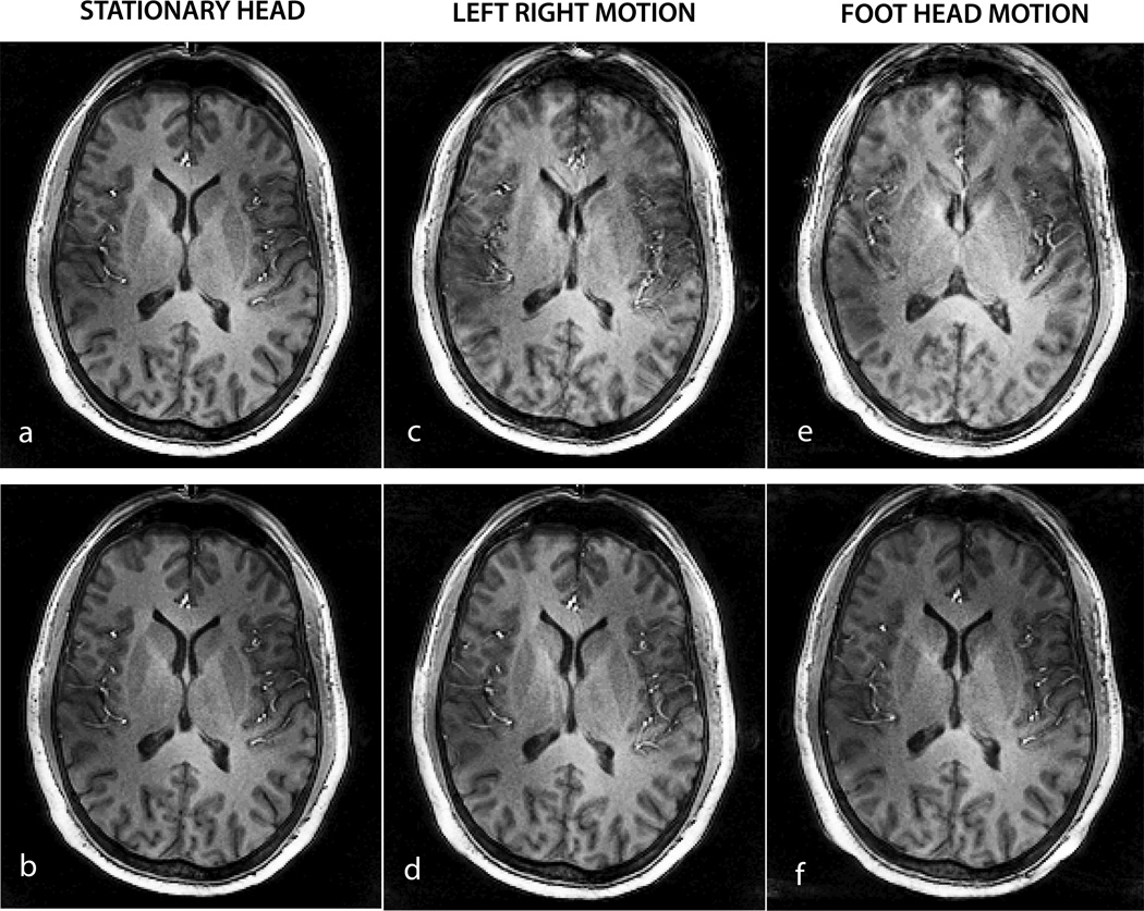
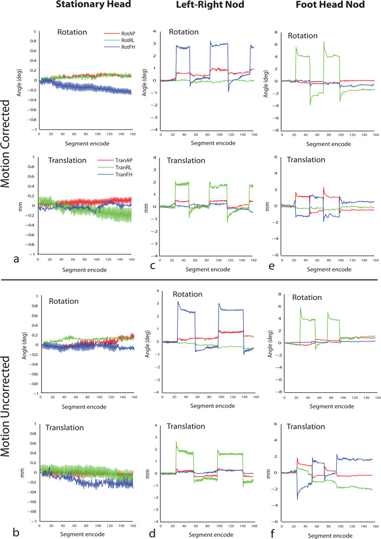
Figure 7 shows the results of 1×1×2 mm3 resolution MPRAGE imaging with motion correction in a human volunteer. According to system log outputs, the maker triangle matching algorithm and the geometry update were reported to span ~17 milliseconds. Figure 7a shows one axial slice from the 20 slice volume acquired without and with the motion correction for the three different motion patterns, i.e. stationary head, left-right nods and foot-head nodding motion. Figure 8 shows the corresponding rotations and translations recorded for all the cases of motion. Significant degradation of image quality is seen in the acquisitions without motion correction. Image quality is improved significantly with prospective motion correction for all cases of motion. Gray-white matter contrast over the whole brain as well as visualization of the cortical boundaries and internal structures including the ventricles, putamen, caudate nuclei and blood vessels is restored to near stationary image quality with real time motion correction. Image quality metric measure for the individual slice displayed reduced from 0.5269 to 0.5268 for the stationary case, 0.5598 to 0.5454 for left-right motion, and 0.5603 to 0.5590 for the through-plane motion case.
Figure 7.
Results of real time motion correction in 1× 1× 2 mm3 resolution MPRAGE imaging in a human subject. Single slice data is shown with correction of inplane left-right nodding with sharp transitions (7c & 7d) and foot head nodding (7e & 7f). Excellent image quality is restored in the presence of significant head motion shown in Fig 8.
Fig 8.
(a –e): Motion traces of head motion in MPRAGE image shown in Fig 7.
Figure 9 shows the results of 0.8 mm×0.8 mm inplane resolution T2* weighted GRE imaging. Fine structures such as thin vessels are successfully preserved in the presence of continuous head motion using the proposed motion correction strategy. Without motion correction, the image is corrupted severely. Image quality metric measure for the output image reduced from 0.5994 to 0.4967 with correction for the moving case. The values for the uncorrected and corrected images without intended motion were 0.4525 and 0.4541. The time durations of the scan without and with the motion correction module were 1 minute 44 seconds and 1 minute 49 seconds.
Fig 9.
Results of real time motion correction in 0.8 mm×0.8 mm×3 mm T2* weighted GRE imaging. (a,b): images showing stationary head without and with motion correction. (c,d) : Motion traces of a and b. (e,f) : images showing continuously moving head without and with motion correction.(g,h) Motion traces of e and f.
DISCUSSION AND CONCLUSIONS
This work demonstrates the use of inductively coupled wireless NMR probes for real-time 6DOF head motion estimation and correction in MRI. An algorithm for detecting individual marker positions in 3D space from full field of view navigator data has been introduced. Individual marker and system performance has been characterized. Real time prospective motion correction of the head in high resolution GRE and MPRAGE imaging has been demonstrated at 7 Tesla.
The benefits of using semi-active markers for motion correction are manifold. Firstly, semi-active markers eliminate the need for spare receiver channels. This is a practical bottleneck in the use of active markers, which may limit its translation to clinical applications. With semi-active markers, the system can be utilized economically with existing setups, without the need for additional channel switching hardware. Also, eliminating the need for spare channels enables use in any potential receiver setups, such as those used in single channel coils. Secondly, without cable connections to the markers, the possibilities of cable currents are eliminated. The occurrences of susceptibility induced shading and RF shading artifacts in the images due to cables passing close to the head are avoided. Thirdly, semi-active markers are considerably smaller in size compared to active markers, since cable connections and matching capacitors are not needed. This significantly increases the flexibility of marker placement inside the head coil where space is typically limited and fixation of active makers and cable routing, difficult. The size and flexibility benefits also lead to considerable enhancement in patient comfort with wireless markers. They can be fixed to the head much more rigidly than active markers where headband slippage and cable tensions introduce errors in motion estimation. Also, semi-active makers can be easily integrated with stimulus input devices such as goggles and earphones, making them significantly more amenable to functional MRI scans. Finally, the construction of semiactive markers is considerably easier than wired markers. This is important not only in the initial construction but also in the maintenance and replacement of these markers.
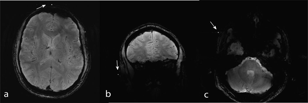
The primary challenge in wireless marker based motion correction is obtaining high SNR from the markers. The accuracy of the motion correction system is directly dependent on the SNR and the peak width. In comparison to wireless markers, wired markers yield significantly higher SNR, smaller peak linewidth and as a result, higher accuracy. However, the other advantages of wireless implementation described above may eventually lead it to prevail over wired markers in clinical and research adoption. With wireless marker design modification and optimization in the future targeted particularly towards maximizing signal levels, wireless marker based motion correction may provide sufficiently high performance for routine imaging needs. One drawback of marker based motion correction is that the makers are apparent with high intensity if a slice with the marker is selected for imaging. This is shown in Figure 10, acquired on a stationary volunteer, where the markers appear as hyper-intense spots in the image. The markers are not visible in the single slice GRE imaging data if a marker does not fall in the imaged slice.
Fig 10.
Axial (a & c) and coronal (b) slices with markers appearing as a hyper-intense spots (white arrows).
Safety is a concern in the use of semi-active markers. In the absence of active detuning, RF energy is deposited during the high flip angle imaging excitations throughput the scan. In our tests, the temperature of the markers did not rise above the noise levels of the baseline measurements under high average power and duration 3D GRE and FSE sequences. An option for detuning the markers during high flip angle excitations is the use of crossed low switching time Schottky diodes in parallel with the resonant circuit. For ~1° excitations during the navigator module, these diodes will remain off, and the marker will remain on resonance. For higher RF power excitations during the imaging sequence, the diodes will turn on, detuning the circuit. Another option for detuning semi-active markers with minimal hardware addition is the use of optical diodes as demonstrated by Eggers et al (34).
The algorithm presented in this paper has a drawback in the manner of selection of the initial reference triangle. Since the projection peaks are indexed as 1,2,3 from the highest to lowest intensities in each direction, if the same marker does not have the highest (or corresponding) intensity in all three directions of the first navigator set, the reference triangle is no longer the actual probe triangle, rather a 'virtual' triangle that may not be on the head. Tracking this virtual triangle may not yield correct motion parameters, as there is no guarantee that the virtual triangle will move the same way as the actual marker triangle. For all subsequent navigator modules however, the algorithm can handle this problem. One way of solving this issue would be to measure the intermarker distance before the scan or to mount the markers on a standard frame worn by the subject so that the true side distances are known. This will also help cut down the setup times and fix individual marker orientations.
The marker identification algorithm performance will degrade with excessive noise in marker peak localization. Also, when markers overlap along any direction, errant peaks are selected as a result of picking of background points as marker positions. In such cases however, the calculated motion parameters often exceed the threshold limits and motion correction is not performed. However, even in cases of overlapping markers, the correct marker triangle does exist among the triangles formed by the backprojection of marker peaks. Practically, given the small sizes and flexibility of marker placement, overlapping of markers can be easily avoided for typical ranges of head motion. For the data shown in our results, three distinct marker peaks and the correct triangle were identified along every direction 100% of the time. Future work will focus on increasing the robustness of the algorithm with regard to missing and errant marker peaks. The algorithm is rapid since there are only 36 searchable triangles, the indices of which can be stored in a predefined array. Also, since the algorithm does not make any assumptions regarding the order of the projection peaks, it is robust enough to handle cases of swapped coordinates with just three projections. Recent work by another group using wireless markers for real time motion correction is based on this assumption of the markers being separated sufficiently, so as to not interchange positions for typical degrees of head rotation (40). Such an assumption may prove to be sufficient for typical degrees of head rotations. The algorithm in this paper does fail in cases where a reflected coordinate does not change the normal vector direction significantly. Further work is needed to identify and correct for such cases. In cases where motion correction is skipped, one may use labeling and reacquiring at the end of the scan. Alternatively, an additional projection may be added to detect such cases. The effect on image quality of views in which motion correction is skipped, remains to be investigated. In order to boost the MBC value, navigator excitation can be performed in the moving object frame, targeting a restricted region within the last known plane of the marker triangle, reducing the background signal.
The performance of the current system in terms of accuracy was inferior to optical methods demonstrated at 7 Tesla (20). However, optical methods require extensive calibrations and hardware additions to the scan environments. The accuracy of the marker-based system may be improved to rival the optical systems by implementing microcoil designs in the future. Smaller sample sizes may yield sharper peaks and improve the accuracy of the motion correction. However, smaller sample volumes will also reduce signal levels, which may counterbalance the size benefit. Careful marker designs with susceptibility matching techniques and optimized contrast agent concentrations may be important to regain signal levels and accuracy in microcoil designs. As of today, to our knowledge, there are no implementations of purely navigator based, real time 6DOF motion correction at 7 Tesla.
APPENDIX A
The following 36 × 9 matrix lists the 36 triangle vertex index combinations from which the correct solution triangle is selected. Projection peaks are along direction 1 are indexed 0,1,2 ; those from direction 2 are indexed 3,4,5 and those from direction 3 are indexed 6,7,8.
| Vertex1 Vertex2 Vertex3 |
| {0,3,6, 1,4,7, 2,5,8}, |
| {0,3,6, 1,5,7, 2,4,8}, |
| {0,3,6, 1,4,8, 2,5,7}, |
| {0,3,6, 1,5,8, 2,4,7}, |
| {0,4,6, 1,3,7, 2,5,8}, |
| {0,4,6, 1,5,7, 2,3,8}, |
| {0,4,6, 1,3,8, 2,5,7}, |
| {0,4,6, 1,5,8, 2,3,7}, |
| {0,5,6, 1,3,7, 2,4,8}, |
| {0,5,6, 1,4,7, 2,3,8}, |
| {0,5,6, 1,3,8, 2,4,7}, |
| {0,5,6, 1,4,8, 2,3,7}, |
| {0,3,7, 1,4,6, 2,5,8}, |
| {0,3,7, 1,5,6, 2,4,8}, |
| {0,3,7, 1,4,8, 2,5,6}, |
| {0,3,7, 1,5,8, 2,4,6}, |
| {0,4,7, 1,3,6, 2,5,8}, |
| {0,4,7, 1,5,6, 2,3,8}, |
| {0,4,7, 1,3,8, 2,5,6}, |
| {0,4,7, 1,5,8, 2,3,6}, |
| {0,5,7, 1,3,6, 2,4,8}, |
| {0,5,7, 1,4,6, 2,3,8}, |
| {0,5,7, 1,3,8, 2,4,6}, |
| {0,5,7, 1,4,8, 2,3,6}, |
| {0,3,8, 1,4,6, 2,5,7}, |
| {0,3,8, 1,5,6, 2,4,7}, |
| {0,3,8, 1,4,7, 2,5,6}, |
| {0,3,8, 1,5,7, 2,4,6}, |
| {0,4,8, 1,3,6, 2,5,7}, |
| {0,4,8, 1,5,6, 2,3,7}, |
| {0,4,8, 1,3,7, 2,5,6}, |
| {0,4,8, 1,5,7, 2,3,6}, |
| {0,5,8, 1,3,6, 2,4,7}, |
| {0,5,8, 1,4,6, 2,3,7}, |
| {0,5,8, 1,3,7, 2,4,6}, |
| {0,5,8, 1,4,7, 2,3,6}; |
Contributor Information
Saikat Sengupta, Email: saikat.sengupta@vanderbilt.edu.
Sasidhar Tadanki, Email: sasidhar.tadanki@vanderbilt.edu.
John C. Gore, Email: john.gore@vanderbilt.edu.
E. Brian Welch, Email: brian.welch@vanderbilt.edu.
REFERENCE
- 1.Ehman RL, Felmlee JP. Adaptive technique for high-definition MR imaging of moving structures. Radiology. 1989;173:255–263. doi: 10.1148/radiology.173.1.2781017. [DOI] [PubMed] [Google Scholar]
- 2.Korin HW, Felmlee JP, Ehman RL, Riederer SJ. Adaptive technique for three-dimensional MR imaging of moving structures. Radiology. 1990;177:217–221. doi: 10.1148/radiology.177.1.2399320. [DOI] [PubMed] [Google Scholar]
- 3.Fu ZW, Wang Y, Grimm RC, Rossman PJ, Felmlee JP, Riederer SJ, Ehman RL. Orbital navigator echoes for motion measurements in magnetic resonance imaging. Magn Reson Med. 1995;34:746–753. doi: 10.1002/mrm.1910340514. [DOI] [PubMed] [Google Scholar]
- 4.Welch EB, Manduca A, Grimm RC, Ward HA, Jack CR., Jr Spherical navigator echoes for full 3D rigid body motion measurement in MRI. Magn Reson Med. 2002;47:32–41. doi: 10.1002/mrm.10012. [DOI] [PubMed] [Google Scholar]
- 5.Anderson AW, Gore JC. Analysis and correction of motion artifacts in diffusion weighted imaging. Magn Reson Med. 1994;32:379–387. doi: 10.1002/mrm.1910320313. [DOI] [PubMed] [Google Scholar]
- 6.Pipe JG. Motion correction with PROPELLER MRI: application to head motion and free-breathing cardiac imaging. Magn Reson Med. 1999;42:963–969. doi: 10.1002/(sici)1522-2594(199911)42:5<963::aid-mrm17>3.0.co;2-l. [DOI] [PubMed] [Google Scholar]
- 7.Ardekani BA, Bachman AH, Helpern JA. A quantitative comparison of motion detection algorithms in fMRI. Magn Reson Imaging. 2001;19:959–963. doi: 10.1016/s0730-725x(01)00418-0. [DOI] [PubMed] [Google Scholar]
- 8.Bammer R, Aksoy M, Liu C. Augmented generalized SENSE reconstruction to correct for rigid body motion. Magn Reson Med. 2007;57:90–102. doi: 10.1002/mrm.21106. [DOI] [PMC free article] [PubMed] [Google Scholar]
- 9.Atkinson D, Hill DL, Stoyle PN, Summers PE, Keevil SF. Automatic correction of motion artifacts in magnetic resonance images using an entropy focus criterion. IEEE Trans Med Imaging. 1997;16:903–910. doi: 10.1109/42.650886. [DOI] [PubMed] [Google Scholar]
- 10.Korin HW, Felmlee JP, Riederer SJ, Ehman RL. Spatial-frequency-tuned markers and adaptive correction for rotational motion. Magn Reson Med. 1995;33:663–669. doi: 10.1002/mrm.1910330511. [DOI] [PubMed] [Google Scholar]
- 11.Lee CC, Jack CR, Jr, Grimm RC, Rossman PJ, Felmlee JP, Ehman RL, Riederer SJ. Real-time adaptive motion correction in functional MRI. Magn Reson Med. 1996;36:436–444. doi: 10.1002/mrm.1910360316. [DOI] [PubMed] [Google Scholar]
- 12.Lee CC, Grimm RC, Manduca A, Felmlee JP, Ehman RL, Riederer SJ, Jack CR., Jr A prospective approach to correct for inter-image head rotation in fMRI. Magn Reson Med. 1998;39:234–243. doi: 10.1002/mrm.1910390210. [DOI] [PubMed] [Google Scholar]
- 13.Derbyshire JA, Wright GA, Henkelman RM, Hinks RS. Dynamic scan-plane tracking using MR position monitoring. J Magn Reson Imaging. 1998;8:924–932. doi: 10.1002/jmri.1880080423. [DOI] [PubMed] [Google Scholar]
- 14.Ward HA, Riederer SJ, Grimm RC, Ehman RL, Felmlee JP, Jack CR., Jr Prospective multiaxial motion correction for fMRI. Magn Reson Med. 2000;43:459–469. doi: 10.1002/(sici)1522-2594(200003)43:3<459::aid-mrm19>3.0.co;2-1. [DOI] [PubMed] [Google Scholar]
- 15.van der Kouwe AJ, Benner T, Dale AM. Real-time rigid body motion correction and shimming using cloverleaf navigators. Magn Reson Med. 2006;56:1019–1032. doi: 10.1002/mrm.21038. [DOI] [PubMed] [Google Scholar]
- 16.White N, Roddey C, Shankaranarayanan A, Han E, Rettmann D, Santos J, Kuperman J, Dale A. PROMO: Real-time prospective motion correction in MRI using image-based tracking. Magn Reson Med. 2010;63:91–105. doi: 10.1002/mrm.22176. [DOI] [PMC free article] [PubMed] [Google Scholar]
- 17.Thesen S, Heid O, Mueller E, Schad LR. Prospective acquisition correction for head motion with image-based tracking for real-time fMRI. Magn Reson Med. 2000;44:457–465. doi: 10.1002/1522-2594(200009)44:3<457::aid-mrm17>3.0.co;2-r. [DOI] [PubMed] [Google Scholar]
- 18.Zaitsev M, Dold C, Sakas G, Hennig J, Speck O. Magnetic resonance imaging of freely moving objects: prospective real-time motion correction using an external optical motion tracking system. Neuroimage. 2006;31:1038–1050. doi: 10.1016/j.neuroimage.2006.01.039. [DOI] [PubMed] [Google Scholar]
- 19.Qin L, van Gelderen P, Derbyshire JA, Jin F, Lee J, de Zwart JA, Tao Y, Duyn JH. Prospective head-movement correction for high-resolution MRI using an in-bore optical tracking system. Magn Reson Med. 2009;62:924–934. doi: 10.1002/mrm.22076. [DOI] [PMC free article] [PubMed] [Google Scholar]
- 20.Schulz J, Siegert T, Reimer E, Labadie C, Maclaren J, Herbst M, Zaitsev M, Turner R. An embedded optical tracking system for motion-corrected magnetic resonance imaging at 7T. MAGMA. 2012;25:443–453. doi: 10.1007/s10334-012-0320-0. [DOI] [PubMed] [Google Scholar]
- 21.Maclaren J, Armstrong BS, Barrows RT, Danishad KA, Ernst T, Foster CL, Gumus K, Herbst M, Kadashevich IY, Kusik TP, Li Q, Lovell-Smith C, Prieto T, Schulze P, Speck O, Stucht D, Zaitsev Measurement and correction of microscopic head motion during magnetic resonance imaging of the brain. M.PLoS One. 2012;7(11):e48088. doi: 10.1371/journal.pone.0048088. [DOI] [PMC free article] [PubMed] [Google Scholar]
- 22.Forman C, Aksoy M, Hornegger J, Bammer R. Self-encoded marker for optical prospective head motion correction in MRI. Med Image Anal. 2011 Oct;15(5):708–719. doi: 10.1016/j.media.2011.05.018. [DOI] [PMC free article] [PubMed] [Google Scholar]
- 23.Ackerman JL, Offutt MC, Buxton RB, Brady TJ. Rapid 3D tracking of small rf coils. Fifth Annual Meeting, Society of Magnetic Resonance in Medicine; August 18–22, 1986; Montréal, Québec. [Google Scholar]
- 24.Dumoulin CL, Souza SP, Darrow RD. Real-time position monitoring of invasive devices using magnetic resonance. Magn Reson Med. 1993;29:411–415. doi: 10.1002/mrm.1910290322. [DOI] [PubMed] [Google Scholar]
- 25.Kozerke S, Hegde S, Schaeffter T, Lamerichs R, Razavi R, Hill DL. Catheter tracking and visualization using 19F nuclear magnetic resonance. Magn Reson Med. 2004;52:693–697. doi: 10.1002/mrm.20202. [DOI] [PubMed] [Google Scholar]
- 26.Ladd ME, Zimmermann GG, McKinnon GC, von Schulthess GK, Dumoulin CL, Darrow RD, Hofmann E, Debatin JF. Visualization of vascular guidewires using MR tracking. J Magn Reson Imaging. 1998;8:251–253. doi: 10.1002/jmri.1880080142. [DOI] [PubMed] [Google Scholar]
- 27.Coutts GA, Gilderdale DJ, Chui M, Kasuboski L, DeSouza NM. Integrated and interactive position tracking and imaging of interventional tools and internal devices using small fiducial receiver coils. Magn Reson Med. 1998;40:908–913. doi: 10.1002/mrm.1910400617. [DOI] [PubMed] [Google Scholar]
- 28.Krueger S, Wolff S, Schmitgen A, Timinger H, Bublat M, Schaeffter T, Nabavi A. Fast and accurate automatic registration for MR-guided procedures using active microcoils. IEEE Trans Med Imaging. 2007;26:385–392. doi: 10.1109/TMI.2006.889748. [DOI] [PubMed] [Google Scholar]
- 29.Ooi MB, Krueger S, Thomas WJ, Swaminathan SV, Brown TR. Prospective real-time correction for arbitrary head motion using active markers. Magn Reson Med. 2009;62:943–954. doi: 10.1002/mrm.22082. [DOI] [PMC free article] [PubMed] [Google Scholar]
- 30.Ooi MB, Krueger S, Muraskin J, Thomas WJ, Brown TR. Echo-planar imaging with prospective slice-by-slice motion correction using active markers. Magn Reson Med. 2011;66:73–81. doi: 10.1002/mrm.22780. [DOI] [PMC free article] [PubMed] [Google Scholar]
- 31.Burl M, Coutts GA, Young IR. Tuned fiducial markers to identify body locations with minimal perturbation of tissue magnetization. Magn Reson Med. 1996;36:491–493. doi: 10.1002/mrm.1910360326. [DOI] [PubMed] [Google Scholar]
- 32.Shu Y, Elliott AM, Riederer SJ, Bernstein MA. Motion correction properties of the shells k-space trajectory. Magn Reson Imaging. 2006 Jul;24(6):739–749. doi: 10.1016/j.mri.2005.10.038. [DOI] [PubMed] [Google Scholar]
- 33.Busse H, Trampel R, Gründer W, Moche M, Kahn T. Method for automatic localization of MR-visible markers using morphological image processing and conventional pulse sequences: feasibility for image-guided procedures. J Magn Reson Imaging. 2007;26:1087–1096. doi: 10.1002/jmri.21129. [DOI] [PubMed] [Google Scholar]
- 34.Flask C, Elgort D, Wong E, Shankaranarayanan A, Lewin J, Wendt M, Duerk JL. A method for fast 3D tracking using tuned fiducial markers and a limited projection reconstruction FISP (LPR-FISP) sequence. J Magn Reson Imaging. 2001;14:617–627. doi: 10.1002/jmri.1227. [DOI] [PubMed] [Google Scholar]
- 35.Quick HH, Zenge MO, Kuehl H, Kaiser G, Aker S, Massing S, Bosk S, Ladd ME. Interventional magnetic resonance angiography with no strings attached: wireless active catheter visualization. Magn Reson Med. 2005;53:446–455. doi: 10.1002/mrm.20347. [DOI] [PubMed] [Google Scholar]
- 36.Kuehne T, Weiss S, Brinkert F, Weil J, Yilmaz S, Schmitt B, Ewert P, Lange P, Gutberlet M. Radiology. Catheter visualization with resonant markers at MR imaging-guided deployment of endovascular stents in swine. 2004;233:774–780. doi: 10.1148/radiol.2333031710. [DOI] [PubMed] [Google Scholar]
- 37.Eggers H, Weiss S, Boernert P, Boesiger P. Image-based tracking of optically detunable parallel resonant circuits. Magn Reson Med. 2003;49:1163–1174. doi: 10.1002/mrm.10459. [DOI] [PubMed] [Google Scholar]
- 38.Umeyema S. Least squares estimation of transformation parameters between two point patterns. IEEE Trans Pat Anal Mach Intel. 1991;13:376–380. [Google Scholar]
- 39.McGee KP, Manduca A, Felmlee JP, Riederer SJ, Ehman RL. Image metric-based correction (autocorrection) of motion effects: analysis of image metrics. J Magn Reson Imaging. 2000;11:174–181. doi: 10.1002/(sici)1522-2586(200002)11:2<174::aid-jmri15>3.0.co;2-3. [DOI] [PubMed] [Google Scholar]
- 40.Ooi MB, Aksoy M, Maclaren JR, Watkins RD, Bammer R. Prospective Rigid-Body Motion Correction Using Miniature Wireless RF-Coils as Position Tracking Probe. Proceedings of the 21st Annual Meeting of ISMRM; Salt Lake City, USA. 2013. p. 305. [Google Scholar]


