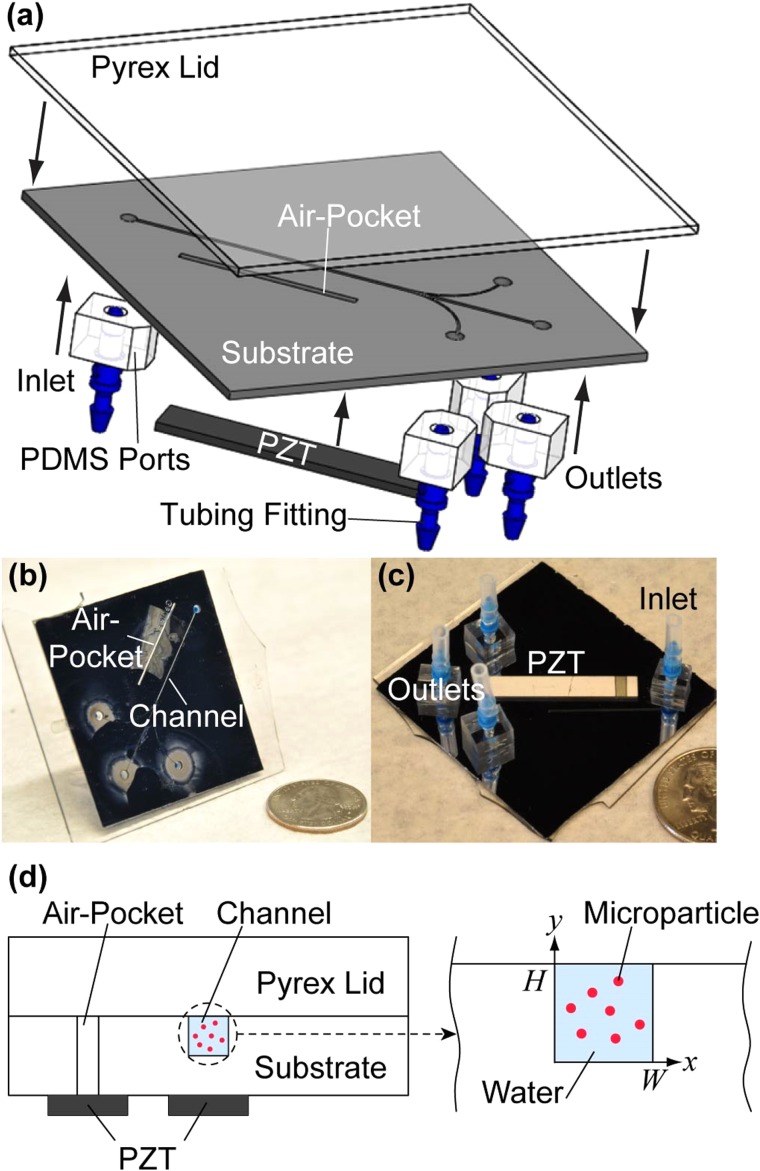
FIG. 1.
Experimental setup. (a) An illustration of the acoustofluidic chip components. (b) Top side and (c) bottom side of the microfluidic device show the positions of the air pocket, inlets, and outlets as well as the placement of the PZT transducer. (d) An illustration of the two locations where the PZT transducers were placed in our experiments relative to the microchannel. These two PZT transducers are referred to as “air pocket PZT” transducer and “channel PZT” transducer in the text. We note that only one PZT transducer was bonded to the microchannel for each experiment.

