

Abstract
Background
Irreversible electroporation (IRE) is (virtually) always called non-thermal despite many reports showing that significant Joule heating occurs. Our first aim is to validate with mathematical simulations that IRE as currently practiced has a non-negligible thermal response. Our second aim is to present a method that allows simple temperature estimation to aid IRE treatment planning.
Methods
We derived an approximate analytical solution of the bio-heat equation for multiple 2-needle IRE pulses in an electrically conducting medium, with and without a blood vessel, and incorporated published observations that an electric pulse increases the medium's electric conductance.
Results
IRE simulation in prostate-resembling tissue shows thermal lesions with 67–92°C temperatures, which match the positions of the coagulative necrotic lesions seen in an experimental study. Simulation of IRE around a blood vessel when blood flow removes the heated blood between pulses confirms clinical observations that the perivascular tissue is thermally injured without affecting vascular patency.
Conclusions
The demonstration that significant Joule heating surrounds current multiple-pulsed IRE practice may contribute to future in-depth discussions on this thermal issue. This is an important subject because it has long been under-exposed in literature. Its awareness pleads for preventing IRE from calling “non-thermal” in future publications, in order to provide IRE-users with the most accurate information possible. The prospect of thermal treatment planning as outlined in this paper likely aids to the important further successful dissemination of IRE in interventional medicine. Prostate 75:332–335, 2015. © 2014 The Authors. The Prostate Published by Wiley Periodicals, Inc.
Introduction
Irreversible electroporation (IRE) is (virtually) always called non-thermal 1,2, despite many reports showing that significant Joule heating occurs, that is, by mathematical modeling (e.g., 3), from measured temperatures that irreversibly injure tissues 4 and by histology showing coagulative necrosis in IRE-affected regions (e.g., 1,2,4–6). The classification “non-thermal” suggests that IRE at any setting induces cell death without the danger of Joule heating which make IRE procedures prone to serious thermal-related complications. Our first aim is therefore to validate with mathematical simulations that currently practiced IRE, in this paper comprising 1.5 or 2 kV over a needle-pair of 1 cm distance, 100 pulses of 0.1 ms duration per pulse and 1 Hz repetition frequency, has a non-negligible thermal response. Our second aim is to present a method that allows simple thermal treatment planning of IRE procedures. To achieve these goals, we will mathematically simulate the temperature response of multiple pulsed 2-needle IRE by (1) deriving an approximate analytical solution of the bio-heat equation for this IRE configuration in an electrically conducting medium, with and without a blood vessel, and (2) incorporating published observations that an electric pulse increases the medium's electric conductance. Finally, we compare the simulations with literature results.
Method
IRE Case 1: Tissue
We adopt the electric field distribution, E (kV/cm), as calculated by Davalos and Rubinsky 3 for 2 kV over a 1 cm needle distance. Their Figure 3B gives the resulting temperatures, ΔTmax, at the end of an electric pulse of Δt = 0.51 ms in tissue with an electric conductance of σ0 = 0.2 S/m from ΔTmax(r,Δt) = (σ0E(r)2/ρc) × Δt, with radial coordinate r, mass density ρ ≈ 103 (kg/m3) and heat capacity c ≈ 3.5 × 10³ (J/kg/°C). The essence of our method is that we approximate ΔTmax by a Gaussian radial function and determine its 1/e-value at r = r0. With these two parameters the bio-heat Equation (1) below can be analytically solved, also for t ≫ Δt. The ΔTmax(r,Δt) curve of Figure 3B of 3 fits well as ΔTmax(r,0.51) ≈ ΔT0exp(−1.4 · r2), with ΔT0 = 21°C and r0 = 0.85 mm, from fitting ΔTmax at r = 0.5 and 0.828 mm. In our simulations we use 0.1 ms and 0.3 S/m (for prostate tissue 1), so ΔT0 = 6.28°C for 2 kV and 3.53°C for 1.5 kV. Further, σ0 increases during each IRE pulse 7 and the top of the peaks of Figure 4 of 7 fitted well to 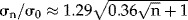 . At longer times, ΔT(r,t) follows from the solution of the bio-heat equation, which conserves the volumetric rates of heat produced by E and removed by thermal conduction. Ignoring heat loss by tissue perfusion 3, it is
| 1 |
with thermal diffusivity α ≈ 0.13 mm2/s and 2nd order differential (Laplace) operator ∇2(m−2). Equation (1) has no simple general analytical solution. However, the Gaussian profile defined above may be thought to originate from radial cooling of an “instantaneous line source of heat” (8, Equation (1) of page 258) during time period τ = r02/4α ≈ 1.4 sec, where τ is the time constant for heat conduction. Then, a short IRE pulse at t = 0 has the simple thermal analytical solution to Equation (1) of
| 2 |
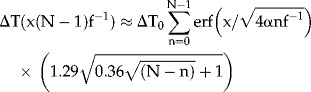
Equation (1) is linear in ΔT so ΔT-responses to multiple pulses can be added as follows. We use that the 1st pulse, at t = 0, yields ΔT1(r,0) = ΔT0F1(r,0)σ1/σ0. Just after the 2nd pulse, say 1 sec later, the 1st pulse reduced to ΔT1(r,1) = ΔT0F1(r,1)σ1/σ0. The 2nd pulse gives ΔT2(r,1) ≡ΔT0F1(r,0)σ2/σ0, thus proportional to the response of the 1st pulse at t = 0. Two pulses, at t = 1 sec, thus cause ΔT2(r,1) = ΔT0[F1(r,0)σ2/σ0 + F1(r,1)σ1/σ0], that is, including the two responses to the first pulse at the two pulse events. Similarly, three pulses, at t = 2 sec, give ΔT(r,2) = ΔT0[F1(r,0)σ3/σ0 + F1(r,1)σ2/σ0 + F1(r,2)σ1/σ0]. Writing this as  , using Equation (2) and including pulse rate f (Hz), approximately solves Equation (1) analytically following N consecutive pulses, at t = (N − 1)f−1 sec, as
 |
3 |
IRE Case 2: Tissue With (Large) Blood Vessel
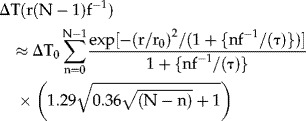
Two-needle IRE around a blood vessel can be simulated if blood flow removes the heated blood between pulses, keeping the intima at 37°C. An analytical solution to Equation (1) is available if radial cooling of the vessel wall is approximated by 1-D diffusion in the x-direction (intima at x = 0, Fig. 1), implying that the perivascular tissue becomes a 1-D semi-infinite medium. Using 8, Equation (1) of page 85, and that each pulse increases the whole perivascular tissue by ΔT0 °C, solves Equation (1) as ΔT(x,t) = ΔT0erf(x/ ). Thus, as Equation (3), an approximate solution of Equation (1) following N consecutive pulses, at t = (N − 1)f−1 sec, is
Figure 1.
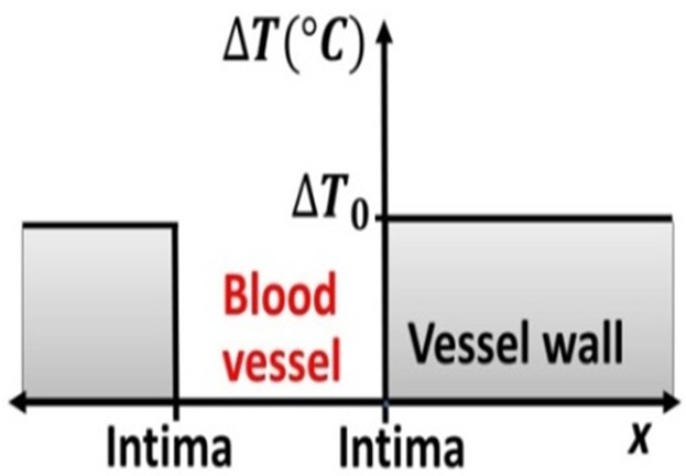
IRE around a blood vessel and 1-D heat conduction in the x-direction. The needles are assumed to be placed at 5 mm from the “center of the blood vessel.”
 |
4 |
Results
Figure 2 shows simulations for f = 1 Hz.
Figure 2.
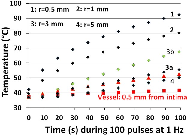
Simulated temperatures, Equation (3), of 100 pulses of 2-needle IRE, for 1.5 kV over 1 cm distance, Δt = 0.1 ms, at 1 Hz, for prostate-resembling tissue 1 without (curves 1, 2, 3a, 3b, 4) and with a blood vessel, Equation (4), for 2 kV (red symbols). Curves 1, 2, 3a, 4 have been computed by fitting Figure 3B of 3 at radii 0.5 and 0.828 mm, and curve 3b by fitting two Gaussian functions at radii 0.5 and 0.828 mm (1st Gaussian) and 2 and 5 mm (2nd Gaussian), converted as before to 1.5 kV, Δt = 0.1 ms, and σ0 = 0.3 S/m, as: ΔTmax = 3.86 · exp [−(r/0.603)2] + 0.215 · exp [−(r/3.892)2]. Curves 1, 2, and 4 do not change much when using two Gaussians compared to one. The red triangles between curves 3a and 4 represent the curve “Vessel: 2 mm from intima.”
IRE Case 1
For prostate tissue, 1.5 kV over 1 cm, Δt = 0.1 ms, N = 100 1, a temperature of 92°C occurs at the needle-tissue boundary (curve 1), which falls to 80°C at r = 1 mm (curve 2) and 56°C at r = 3 mm (curve 3a). However, at r = 3 mm, the Gaussian fit used gives ΔTmax ≈ 0 rather than ≈0.55°C which results in an 11°C underestimated temperature at N = 100, thus a better value than 56°C is 67°C (curve 3b), based on including two Gaussian functions for ΔTmax (defined in the caption of Fig. 2). Coordinate r = 3 mm matches the position of the lesion margin shown in Figure 4 of 1, implying that these pathology-assessed coagulative necrotic lesions are thermal injuries that correspond with our computed temperatures of 67–92°C.
IRE Case 2
For a (large) blood vessel at r = 5 mm, 2 kV over the needles, ΔT0 ≈ 0.15°C (from ΔT0 ≈ 0.5°C in Figure 3B of 3), we simulate a temperature of 41°C close to the intima but 53°C at 2 mm from the intima (thus at r = 3 mm). We neglected the extra ≈ 0.5°C shown in Figure 3B of 3 at r = 3 mm which would have added another ≈10°C. In our opinion, this explains for the first time why IRE of blood vessels is effective and safe 6. It suggests a clinical role for matching the measured blood flow with the IRE pulse frequency.
Discussion
The message of this paper is that although one single IRE pulse may raise the temperature a few degrees only, 100 consecutive pulses can produce temperatures that easily injure tissues irreversibly. From that standpoint, IRE is not different from other Joule heating-based therapies. Particularly, tissues of large electric conductance warrant caution during IRE, for example, urine (1.9 S/m 9) within the renal collecting system and bile ducts when filled with bile (1.27 S/m 9).
To the best of our knowledge, we are the first to analytically solve, albeit approximately, the temperature response to multiple-pulsed IRE by fitting the electric field distribution to a Gaussian function. The linearity of Equation (1) in ΔT obviously allows this approach to be extended to the use of more than just one Gaussian (see curve 3b of Fig. 2 for two Gaussians). Thermal treatment planning becomes simple now, based on Equation (3), and can conceptually be extended to multiple-needle IRE geometries with programmed activation of the various needle-pairs. Treatment planning before—as well as temperature measurements during—IRE oncologic procedures are particularly important because insufficient thermal effects at the boundaries of treated lesions are notorious for causing tumor recurrence.
Compared to the numerical analysis in 10, we achieved very similar results, for example, the first two T-peaks of their Figure 5, that is, T ≈ 33.8 and ≈34°C in response to 40 pulses of 0.5 kV over 0.5 cm and 0.05 ms, in sets of 20 separated by 3.5 sec, versus our estimates of ≈33.7 and 34.2°C. Further, the literature gives thermal evaluations of 2-plate and multiple-needle IRE. The former has negligible heat conduction during multiple pulses, the latter likely gives slightly higher temperatures compared to 2-needle IRE. As an example, Faroja et al. 4 measured temperatures as high as 84°C of 2-plate IRE (their Table 1) in in vivo porcine liver, using 2.5 kV over a 1 cm plate distance and 360 pulses of 0.1 ms at 1 Hz. For 40 and 90 pulses at 2.5 kV they found ΔT ≈ 11 and 18°C. Using ΔT =  and σ0 ≈ 0.09 S/m for liver 9, gave ΔT ≈ 15 and 39°C.
Also, non-thermal IRE effects have been documented, for example, by Gehl et al. (Fig. 3 of 11), using 2-plate IRE around the tibia of mice, eight pulses at 0.2–1.4 kV/cm and Δt of 10–2,000 µs. These authors described perfusion delays of 200–1,800 sec, which they attributed to sympathetic nerve-mediated reflexory vasoconstriction of afferent arterioles, characterized as a Raynaud-like phenomenon and comparable to ST depression observed in the ECG of patients following atrial defibrillation. The reported perfusion delays correspond to simulated temperature increases of 2–33°C.
The thermal nature of IRE may actually have several important therapeutic consequences in terms of cancer treatment. As described in 12, exposure of cancer cells to IRE induces necrotic 1,2,4–6 and possibly apoptotic and/or autophagic cell death. Any of these forms of cell death activates the immune system through sterile inflammation 13, leading to debridement of necrotic tissue followed by tissue remodeling. It is also likely that the adaptive immune system elicits an anti-tumor immune response against residual, viable cancer cells in the treated volume as well as distal, non-treated cancer cells 14.
Conclusion
The demonstration that significant thermal effects at current IRE settings cannot be ignored hopefully contributes to future in-depth discussions on thermal issues that surround IRE. This is an important subject because it has long been under-exposed in literature. Such a discussion adds to safer and more precisely planned IRE procedures. The thermal nature of current IRE practice pleads for preventing IRE from calling “non-thermal” in future publications, in order to provide IRE-users with the most accurate information possible. The prospect of treatment planning as outlined above may aid to the important further successful dissemination of IRE in interventional medicine.
References
- 1.Neil RE, Millar JL, Kavnoudias H, Royce P, Rosenfeldt F, Pham A, Smith R, Davalos RV, Thomson KR. In vivo characterization and numerical simulation of prostate properties for non-thermal irreversible electroporation ablation. Prostate. 2014;74:458–469. doi: 10.1002/pros.22760. [DOI] [PubMed] [Google Scholar]
- 2.Golberg A, Yarmush ML. Nonthermal irreversible electroporation: Fundamentals, applications and challenges. IEEE Trans Biomed Eng. 2013;60:707–714. doi: 10.1109/TBME.2013.2238672. [DOI] [PubMed] [Google Scholar]
- 3.Davalos RV, Rubinsky B. Temperature considerations during irreversible electroporation. Int J Heat Mass Transfer. 2008;51:5617–5622. [Google Scholar]
- 4.Faroja M, Ahmed M, Applebaum L, Ben-David E, Moussa M, Sosna J, Nissenbaum I, Goldberg SN. Irreversible electroporation ablation: Is all the damage nonthermal. Radiology. 2013;266:462–470. doi: 10.1148/radiol.12120609. [DOI] [PubMed] [Google Scholar]
- 5.Appelbaum L, Ben-David E, Faroja M, Nissenbaum Y, Sosna J, Goldberg SN. Irreversible electroporation ablation: Creation of large-volume ablation zones in in vivo porcine liver with four-electrode arrays. Radiology. 2014;270:418–424. doi: 10.1148/radiol.13130349. [DOI] [PubMed] [Google Scholar]
- 6.Lee EW, Chen C, Prieto VE, Dry SM, Loh CT, Kee ST. Advanced hepatic ablation technique for creating cell death: Irreversible electroporation. Radiology. 2010;255:426–433. doi: 10.1148/radiol.10090337. [DOI] [PubMed] [Google Scholar]
- 7.Ivorra A, Al-Sakere B, Rubinsky B, Mir LM. In vivo electrical conductivity measurements during and after tumor electroporation: Conductivity changes reflect the treatment outcome. Phys Med Biol. 2009;54:5949–5963. doi: 10.1088/0031-9155/54/19/019. [DOI] [PubMed] [Google Scholar]
- 8.Carslaw HS, Jaeger JC. Conduction of heat in solids. 2nd ed. Oxford: Clarendon Press; 1986. [Google Scholar]
- 9.Gabriel C, Peyman A, Grant EH. Electrical conductivity of tissue at frequencies below 1 MHz. Phys Med Biol. 2009;54:4863–4878. doi: 10.1088/0031-9155/54/16/002. [DOI] [PubMed] [Google Scholar]
- 10.Garcia PA, Rossmeisl JH, Neil RE, Ellis TL, Davalos RV. A parametric study delineating irreversible electroporation from thermal damage based on a minimally invasive intracranial procedure. Biomed Eng Online. 2011;10:34. doi: 10.1186/1475-925X-10-34. (1–21) [DOI] [PMC free article] [PubMed] [Google Scholar]
- 11.Gehl J, Skovsgaard T, Mir LM. Vascular reactions to in vivo electroporation: Characterization and consequences for drug and gene delivery. Biochim Biophys Acta. 2002;1569:51–58. doi: 10.1016/s0304-4165(01)00233-1. [DOI] [PubMed] [Google Scholar]
- 12.Heger M, van Golen RF, Broekgaarden M, van den Bos RR, Neumann HAM, van Gulik TM, van Gemert MJC. Endovascular laser-tissue interactions and biological responses in relation to endovenous laser therapy. Lasers Med Sci. 2014;26:405–422. doi: 10.1007/s10103-013-1490-3. [DOI] [PubMed] [Google Scholar]
- 13.Hirsiger S, Simmen HP, Werner CM, Wanner GA, Rittirsch D. Danger signals activating the immune response after trauma. Mediators Inflamm. 2012;2012:315941. doi: 10.1155/2012/315941. [DOI] [PMC free article] [PubMed] [Google Scholar]
- 14.Thong PS, Ong KW, Goh NS, Kho KW, Manivasager V, Bhuvaneswari R, Olivo M, Soo KC. Photodynamic-therapy-activated immune response against distant untreated tumours in recurrent angiosarcoma. Lancet Oncol. 2007;8:950–952. doi: 10.1016/S1470-2045(07)70318-2. [DOI] [PubMed] [Google Scholar]